 deepankar
3D printed part files can be seen on Thingiverse
Why I made this Project?
I made this project coz i feel there is so much of technology available but still there are many parts of the world where there is either not an awareness or lack of resources to make use technology that can be helpful to people. And disasters can happen anywhere. The application for this robot that i shared above is something that i have seen happening around me. So i thought of creating a solution. A cheap solution for everyone. i have named this rover Rakshak-one whch means Saviour
What this robot is capable of doing?
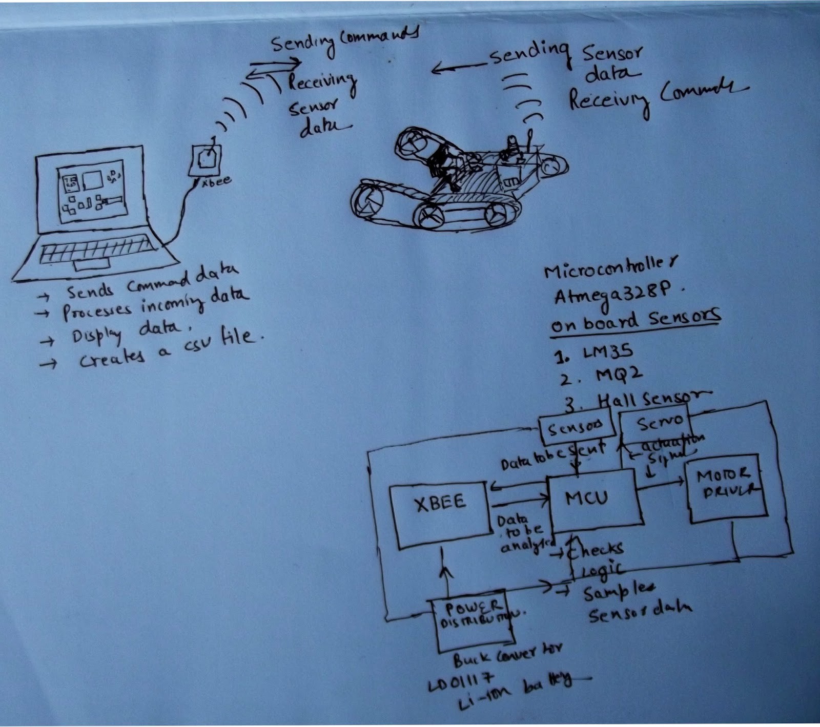
This robot can be controlled by sending commands from the GUI running on the laptop. For wireless transmission of command XBEE series 2 modules are used. The robot can go through different types of terrain,can go through special terrains like the stairs. The GUI software also processes the incoming data and displays it on the screen.
The rover has 3 onboard sensors namely LM35 temerature sensor, MQ2 gas sensor, Hall sensor. The rover gathers the temperature,gas,speed data and sends it back to the GUI. The software processes the incoming data and can also give voice alert if the value of smoke and other gases is above a preset value.The software also records the sensor value changes in a .csv file that can be used to plot the data. The GUI can also display video from a connected camera.
Block Diagram Of the System
Below is a simple block diagram that depicts the functionality of this robotic system.
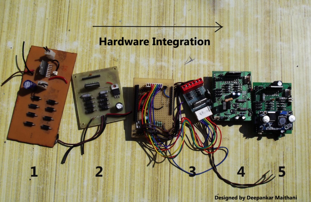
HARDWARE INTEGRATION
The board numbered 1 is the first board on which i tested various motors . The IC used is L298 by STmicroelectronics. The board is a paper epoxy board designed on eagle and completely fabricated at home using the laser printer and hot iron method.Once i found it good i went for a more compact design that is numbered as 2 this is a glass epoxy board ,i ran two of my robots using this board.
I wanted to make a shield(A shield is an arduino compatible pin configuration) so that the hardware can be neatly stacked on the arduino uno .I came across a motor driver on an online shop and i found the design to be very compact. After running the motors of Rakshak-1 on it i understood that it is a overuse of resources and space to go with big power diodes IN5408 for blocking the spikes produced by motors rather a IN4007 would suffice and would make the design compact.
To make the system up and running i needed to have a hardware which can provide different voltages and can give enough power to drive the motors and power the sensors, micro-controller and other peripherals. Initially the GUI software is tested with the hardware arrangement numbered as 3. The shield was handwired and i have used a 11.1 v 1500mAh lithium ion battery to power the system. If you would look closely there are 4 resistors of quarter watt attached in parallel to drop the voltage from 11.1 to 9v This 9v is fed to the motors and 5v regulator provides power to arduino ,IC operations and LM35. Since i couldnot find a single resistor of high wattage adding 4 in parallel solved the wattage problem but still using resistors to drop voltage when current drawn is high is an inefficient method. Hence i decided to use a buck configuration in the next design of shield.
A coil is an integral part of a buck circuitry,but soon i realised that finding a coil of particular value is a uphill task ,i searched on element14 and a few other places but an exact coil was very hard to find ,moreover the price of coil was almost of the same price as that of a buck convertor module that include an IC ,some capacitors LED. So i initially though i will buy a module will desolder the coil and use it on the board i will design but there was another thing that was going to put me in a tight spot and that was the board house. The board house that i had easy access to still follows manual processes so i couldn't route the wires too close,too thin, moreover i have to use the locally available through hole...
Read more »
 Kevin Harrington
 Tom Meehan
 PremJ20