0%
0%
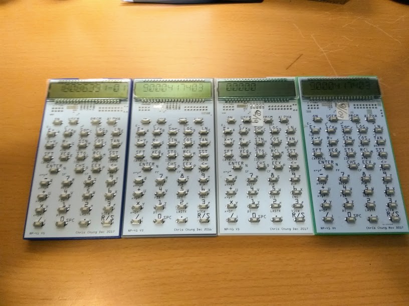
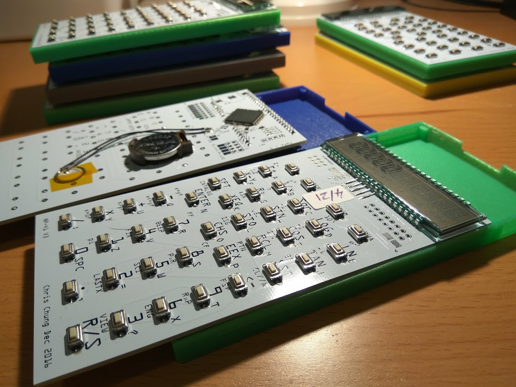
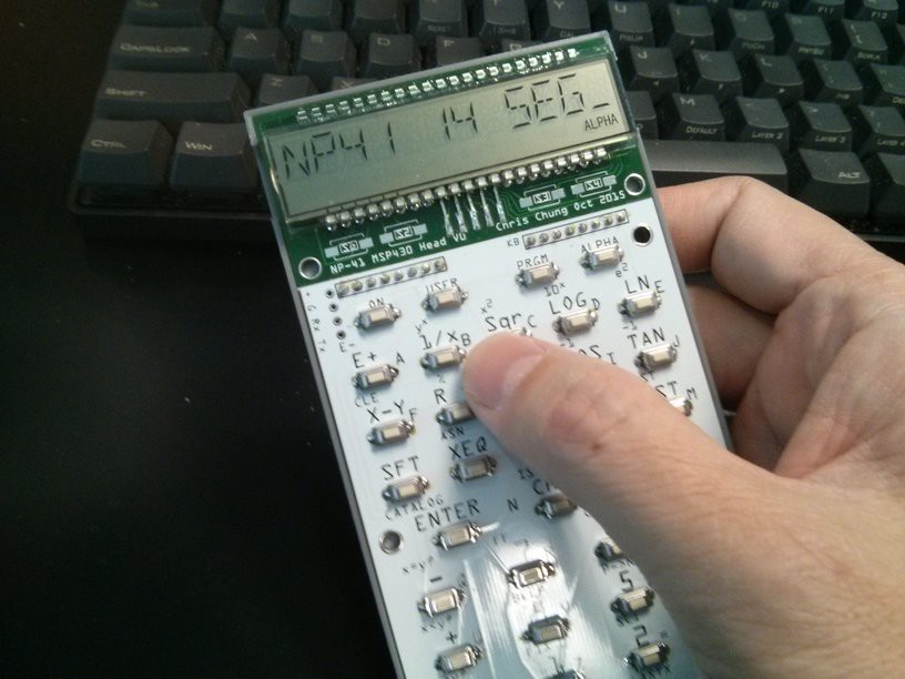
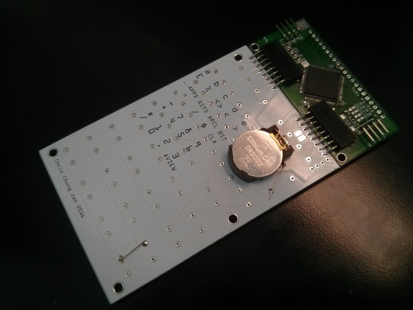
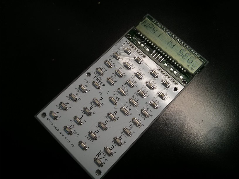
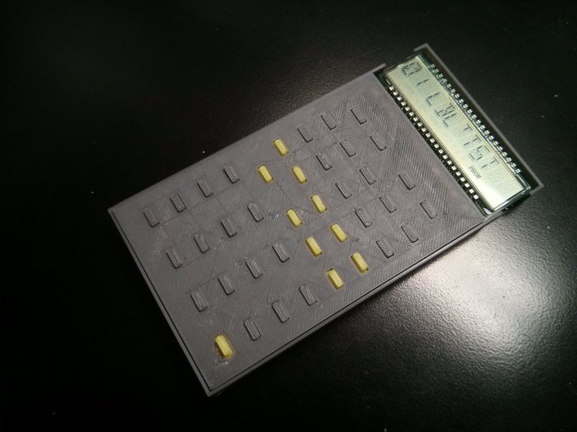
NP-41 RPN Calculator
NP-41 is a hardware realization of the Nonpariel calculator simulator. It executes the original HP-41C / CV byte-codes.
 Chris Chung
Become a Hackaday.io member
Already have an account? Log in.
Just one more thing
To make the experience fit your profile, pick a username and tell us what interests you.
Pick an awesome username
hackaday.io/
Your profile's URL: hackaday.io/username. Max 25 alphanumeric characters.
Pick a few interests
Projects that share your interests
People that share your interests


 Michael Frank Taylor

 Jay8ee
 Nick van de Giesen
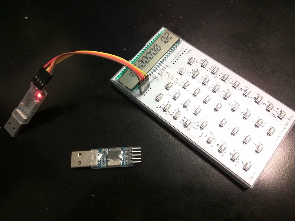
Chris,
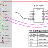
Can you point us at the hardware design? The community might be able to help solve your EMC issue. We’ve probabaly all had to grapple with something like this in a design or two over the years.