 Suleyman Hashi
This was my schematic design of my charger + boost converter. The wiring for the two chips were covered well in their respective datasheet and had a suggested PCB layout as well.
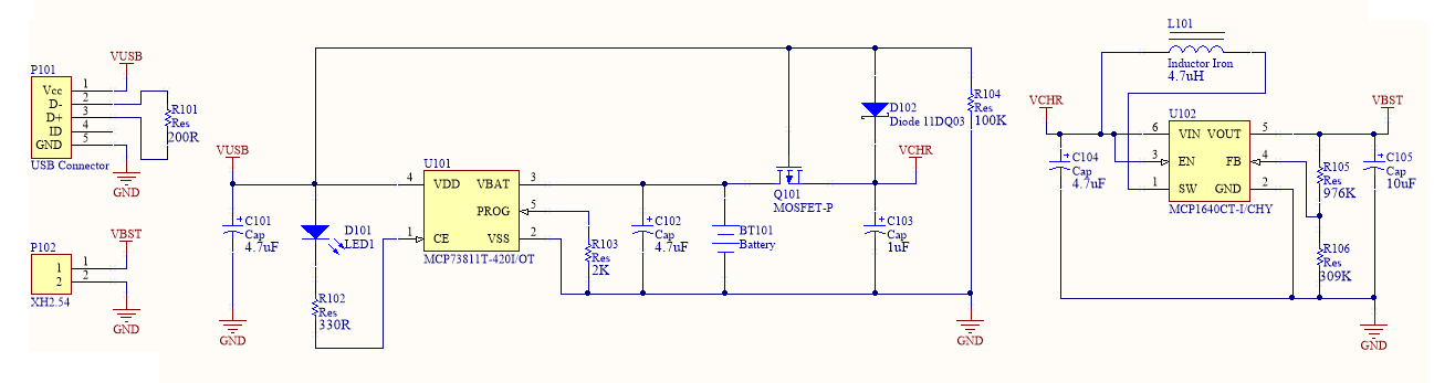
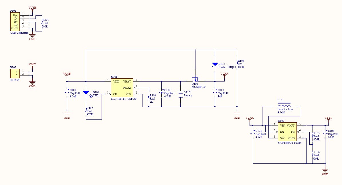 I was informed by K.C. Lee of the incorrect units of the resistors in my boost converter part. I have changed it to the new correct units and the revised schematic is below.
Discussions
Become a Hackaday.io Member
Create an account to leave a comment. Already have an account? Log In.
I like how you implemented the MOSFET to disconnect the battery from the load when charging and use the chargers power instead. It's really clever! Is the 200R between D- and D+ needed? Correct me if I'm wrong, but I did a little reading and I think the 200R is usually inside USB phone chargers to let devices know they are connected to a USB phone charger and can draw over the maximum 500mA. What source did you learn this from? I'm thinking of building up one similar, as I recently used the MCP73831 in a project at work and I like it! My thought is to make your circuit have selectable 3.3V or 5V output, this can be achieved with TPS63000 buck/boost converter instead of MCP1640. What you think?
Are you sure? yes | no
Can't take credit for it. It's based on the Microchip reference circuit covered in AN1149 (http://www.microchip.com/wwwAppNotes/AppNotes.aspx?appnote=en533380) and Zak's Electronics Blog ~* which itself is based on the mentioned application note (http://blog.zakkemble.co.uk/a-lithium-battery-charger-with-load-sharing/).
I've checked the USB-IF website (http://www.usb.org/developers/docs/devclass_docs/) about details of the resistor across the D+ and D-. You right in that resistor is not required unless it's a dedicated charging port e.g. mobile charger. Also checked Sparkfun and Adafruit LiPo charger schematics, and they also do not use the resistor and leave the pins floating.
Thanks for the heads up and I will remove the resistor for the next revision.
That would be cool using the TPS6300 to have the selectable voltages. Let me know how you go with it.
Are you sure? yes | no
Might want to change the units of your boost converter voltage divider. They should be in K.
Are you sure? yes | no
Thanks for notifying me of the error, I am amazed you were able to notice it, I have uploaded a new screen capture to reflect the correct units.
Are you sure? yes | no