 RoGeorge
Table of Contents:
3D Printing AVR Arduino Art Audio Automation BeagleBone Bluetooth Cameras Clock Drones Environment Hardware IoT LED Medical Music Radio Raspberry Pi Remote Control Robotics Rockets Satellites Science Security Software Virtual Reality Wearable
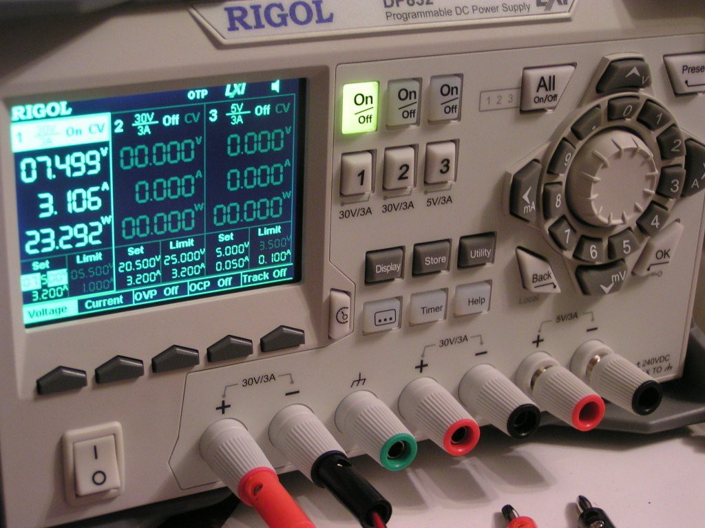 NOTE: This picture is from another project, please ignore the DP832 settings from this picture.
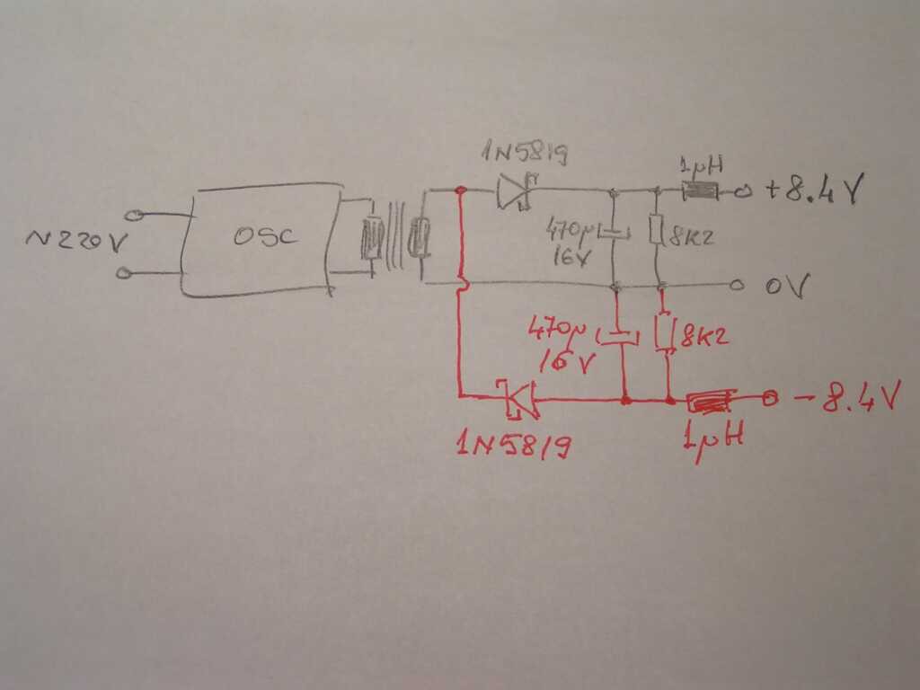
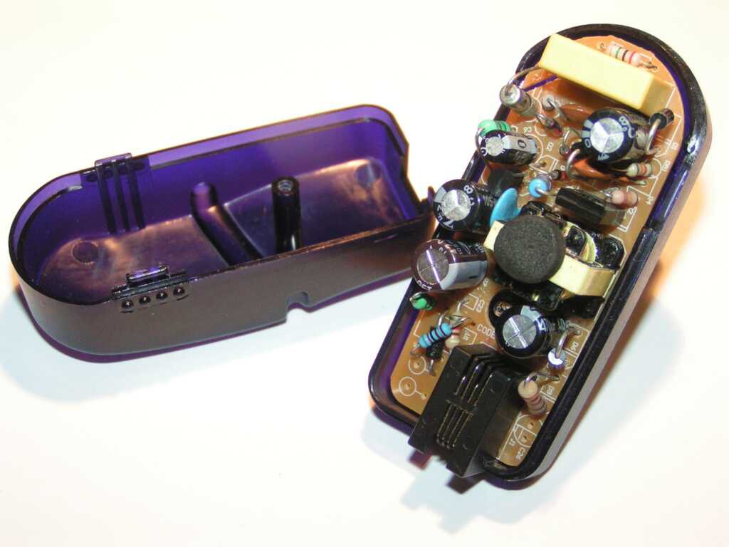 It has a 4 wires RJ9 female connector (like a LAN connector, but with 4 pins only), which was perfect, because I needed at least 3 wires, but preferably 4. Even more, the schematic was very hacker friendly:

 Ted Yapo
 Hacker404
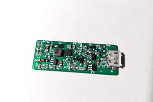
 Sam Ettinger
Hi! Although I'm experienced enough to spot the mistakes instantly,
Thanks for sharing this! I hope that it will save some parts!