 penleeki
First Tests:
Its pretty noisy, I think I may have to build a box to muffle the sound or my neighbors may ask me to stop!
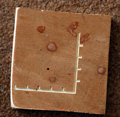
Here are the first test pieces (sandpaper is to stop them moving around):
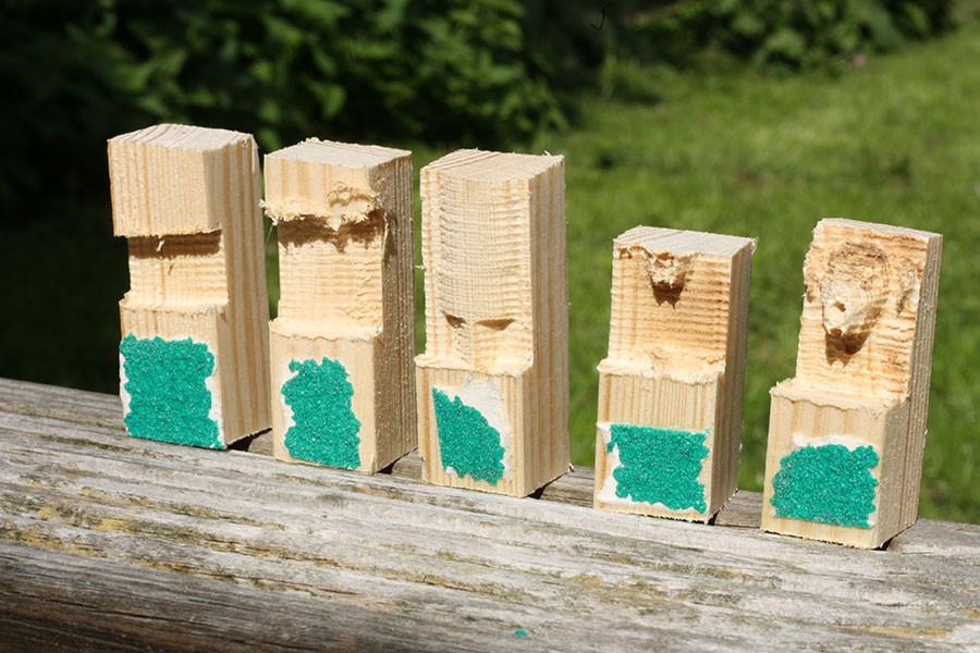
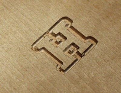
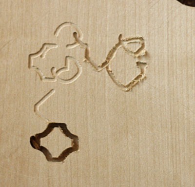
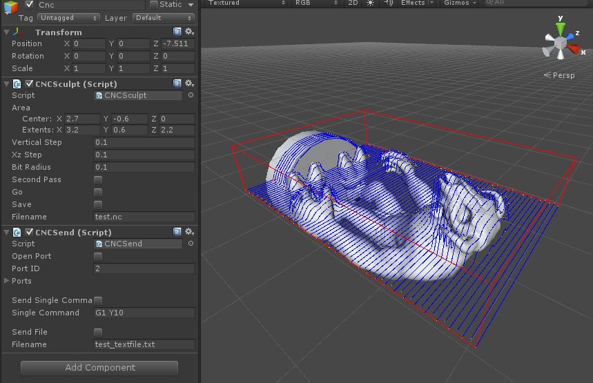
For the first one (on the left) the Z axis broke (screw fell out) and stopped going up and down. I fixed it for the second one, but realised I had a software issue putting the shape in the wrong place. The third one worked fine, so I tried to cut out a more complex shape next (the skull head of a monster from a computer game I'm working on). For the first cut I ran out of wood, but got the size right for the second.
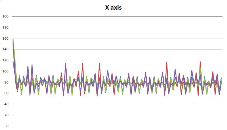
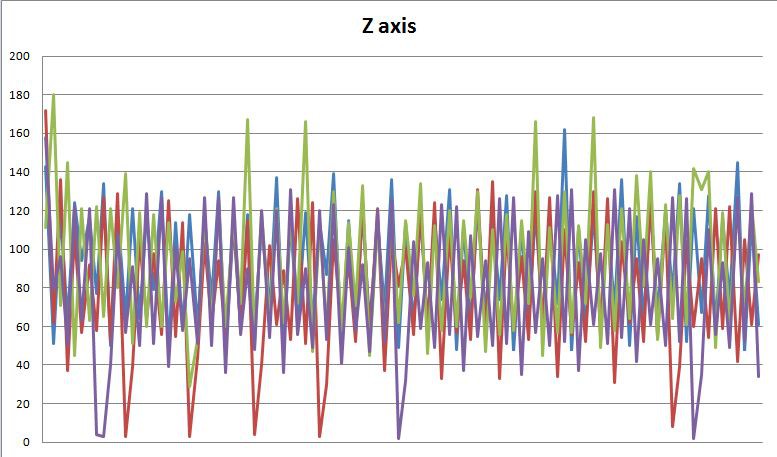
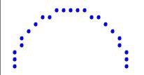
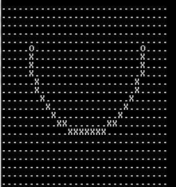
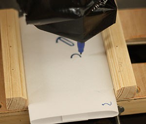
By this point the end mill was starting to burn the wood a bit, and the Z axis was losing its position a little. Since then I've been working on the code (which is available on GitHub) and have started to get some really exciting results:
Tools I have used so far:
- Drill and cheap drill stand
- Dremel
- wood saw
- coping saw
- a little 2.5mm tap
Drilling accurate holes has definitely been one of the hardest things with this project. I had to remake several parts when everything didn't line up quite right. When I tried to fit the bearings onto the rod after drilling a slightly wonky hole (sawdust under the part) it tore the balls out of two of the linear bearings.
Cutting accurate lines was also something I couldn't do, so everything was put together by eye. A drill press and a bandsaw would be really nice things to have! At least I can now cut and drill accurately (though very slowly) on my CNC machine.
The tap (like the Dremel) is one of those tools I never realised I needed until I had it, and now I find all sorts of ways to make use of it. It is a wondrous thing to own and everyone should own at least one.
Things I had lying around that have been used:
- Plywood and other wood of various shapes, sizes and thickness.
- My trusty Dremel.
- A slightly rusty Arduino Leonardo that still works!
- wire and connectors and buttons
- woodscrews and machine screws
I'm using every single pin on the Arduino. At one point I thought I was going to have to buy a Mega, but then I realised you can use the analog pins as digital ones.
Things I have had to buy (so far):
- 6x servos (I had a few and only needed 3 but wanted lots of spares in case I broke some) £10.25
- pack of 10 thrust bearings £11.98
- pack of 12 linear bearings £6.17
- second pack of 12 linear bearings after I broke two of the originals (oops!) £6.17
- 6x 400mm steel rails £22.74
- 5x M5 400mm threaded rod (two spares woo!) £6.35
- pack of 10 roller lever arm microswitches £2.48
- bag of M5 square nuts £1.75
- bag of M5 four prong T nuts £2.35
- pack of 5 2mm ball nose end mills £13.49
Total so far (including postage): £83.73
Not too bad, considering a 3D printer comes in at around £400 minimum last time I looked. Everything was from ebay. I nearly abandoned the idea when I realised how expensive metal rails are. I did not expect a quarter of the cost of the project to be on those.
Mechanics:
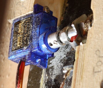
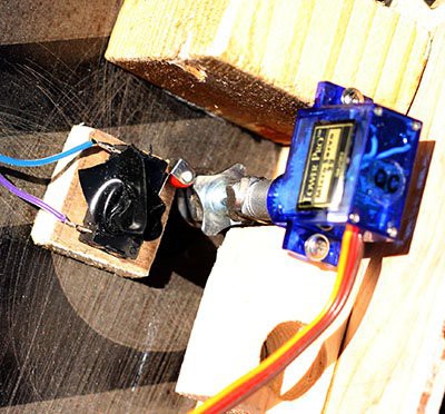
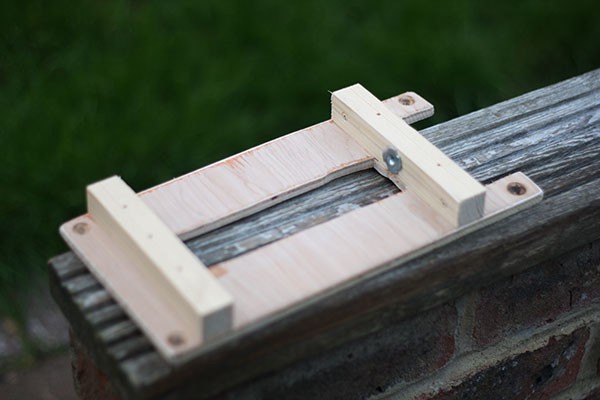
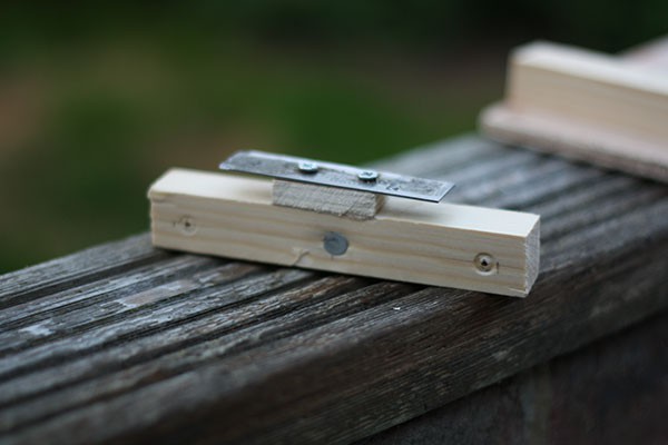
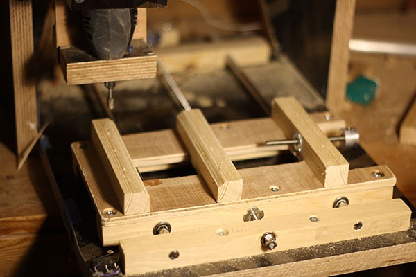
Since the limit switches came in packs of 10 I decided to keep things simple and try and use three of them to keep track of the position of each axis. I didn't want to build some sort of optical/magnet based thing if I didn't have to. I cut down a T nut into a square shape and fitted the switch so it would click in and out
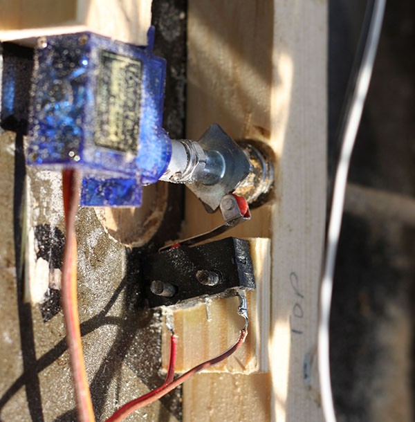
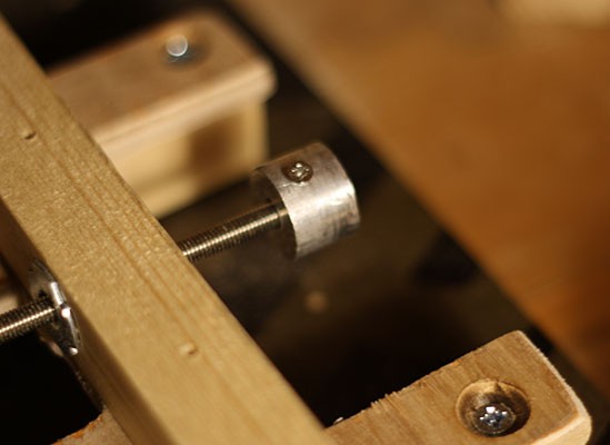
The servo attaches to the threaded rod with a bit of aluminium tube with little home made set screws fitted to it. They fall out due to the vibration of course, so I probably need to superglue them in or something.
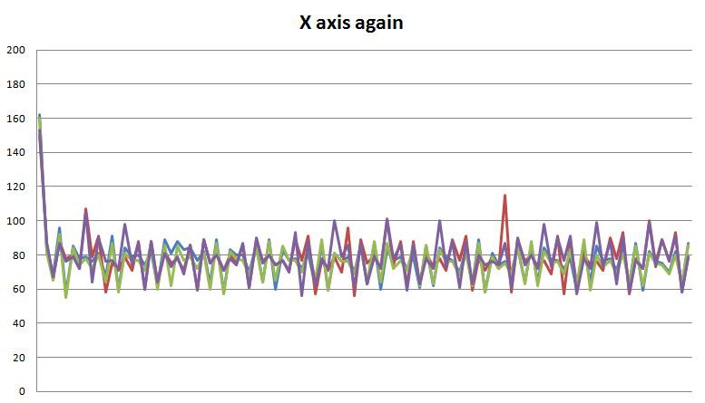
One of the axes wasn't counting properly so I changed the profile a bit which was a big improvement. I should probably do the other two. I also put tape on the switch to stop it wiggling on the nail mounts.
Software:
On the Arduino end I decided to keep things as simple as possible. You send a G Code command over the serial port and it executes it and sends back confirmation. I had a bit of a look for libraries for interpreting G Code and calculating lines and curves, but...
Read more »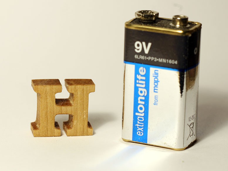


 shlonkin
 Josh
Josh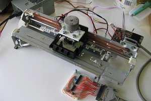
that’s great. I love projects built out of junk - they don’t always work the best but they get the job done.