 Austin Marandos
The Challenge the project addresses:
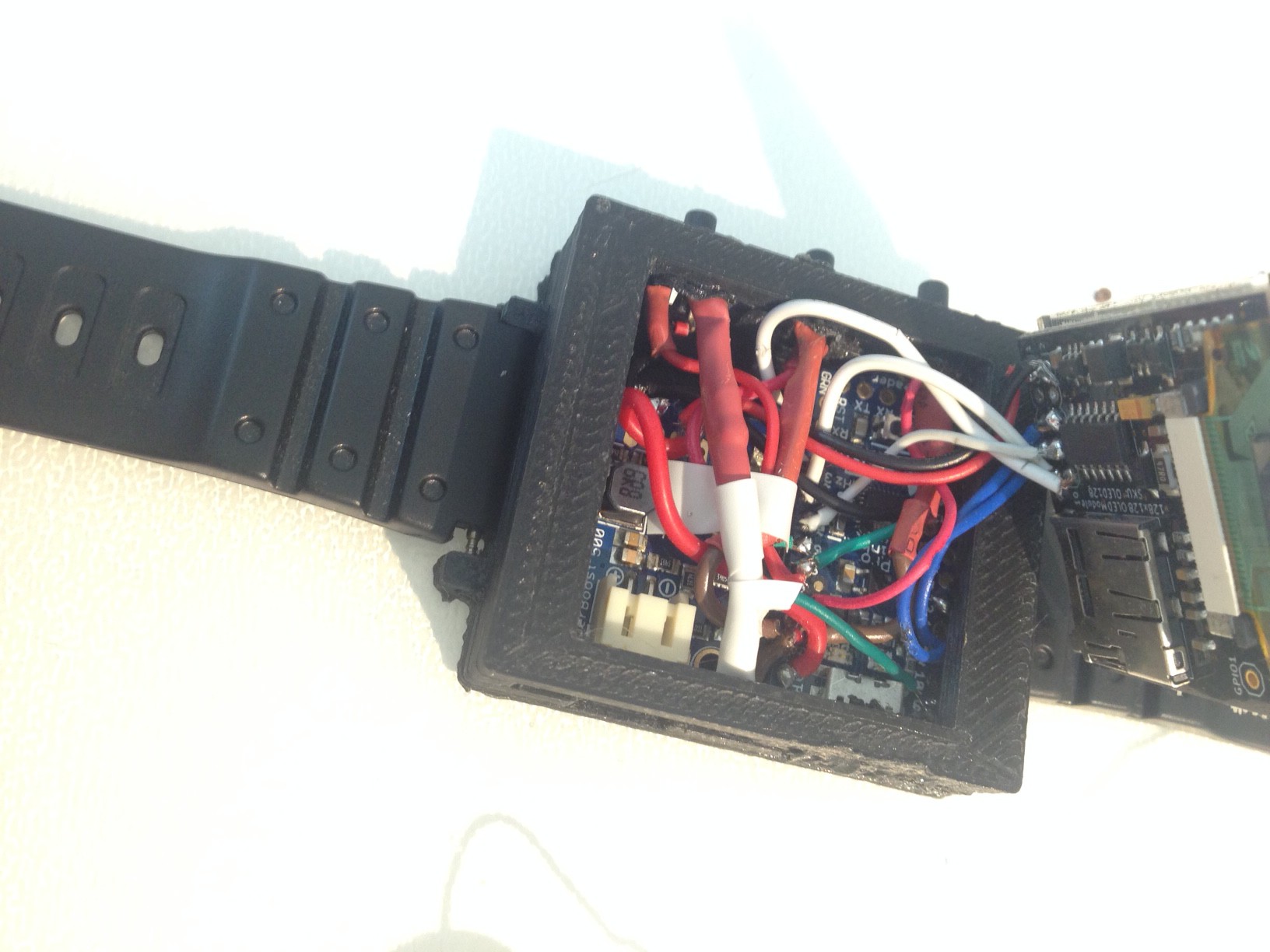
Smart watch accessibility and affordability.
This project aims to create a simple to use fully expandable and open source smart watch platform.
How the project will alleviate or solve the problem:
By providing an open platform for makers to replicate my design smart watch technology should become more common and accessible. The simple approach to my design should also enable younger makers to get involved, possibly using my platform as an education platform.
How the Project will be world changing:
By providing an open source and accessible platform the possibilities are endless. Smart watch technology can be utilised in various different areas including;
- Biomedical technologies (heart rate, fitness etc.).
- IoT technologies
- Business (emails, appointments etc.)
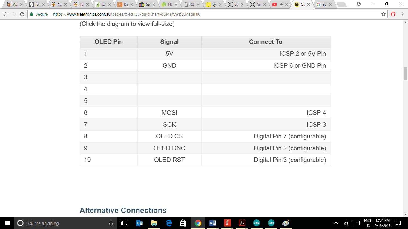
Libraries used:
FTOLED (Oled screen driver)


 Nyeli Kratz
 Anderson Antunes
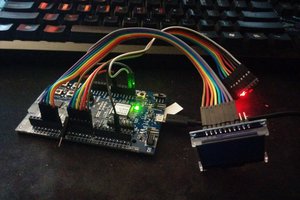
 MicroHex
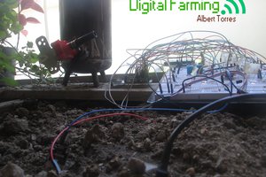
 Albert Torres
So I've been working on a similar project. I recommend checking out crystalfontz. They have a color lcd for $5 that will take your display current from 14ma to 1mA. They even have an arduino library (havent tryed it yet, getting my parts this week) The issue you would run into is you would need to switch to 3.3V (with and buck or ldo regulator off the lipo).