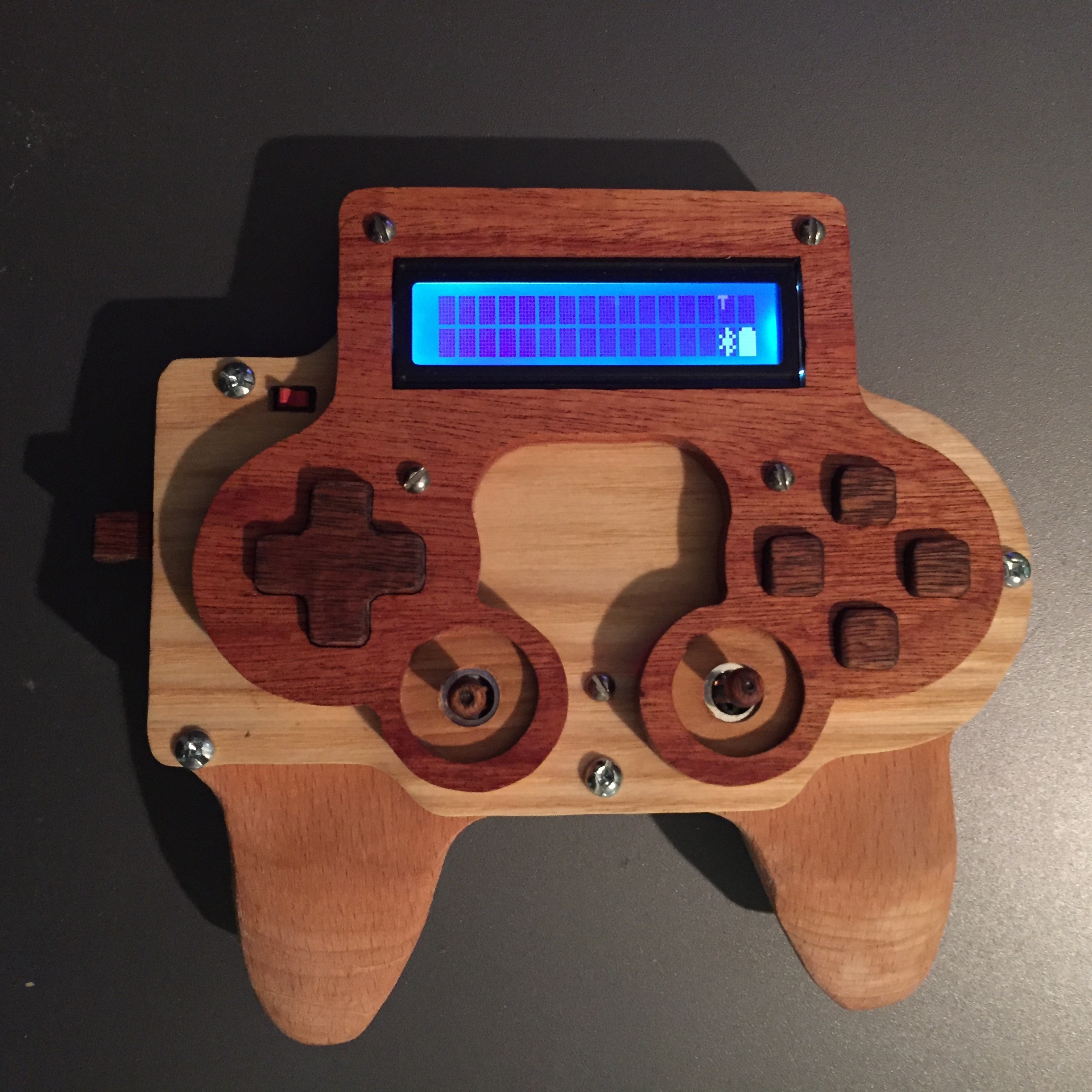
Close
0%
0%

Universal Controller

One controller to rule them all! A PS2 controller crossed with an AVR and XBee / Bluetooth, to use in multiple physical computing projects.

Similar projects worth following
A long time ago, in a galaxy far, far away, everything seems to be able to talk to everything else. Whether that be alien languages ("Going somewhere, Solo?"), or computers (R2 can plug in anywhere), there is never any problem interfacing with other systems.

This project is my attempt to achieve universal communication, starting with at least my own robotics projects. It allows me to reuse a single controller across multiple projects, without needing to reprogram the firmware or change settings every time.

It was started with a (failed) attempt at making quadcopters. Over time, it has evolved into a more generic system with applications for most robotic systems I am working on, and is currently the controller for Stubby the Hexapod (http://hackaday.io/project/770).

This is a pretty simple project, and could quite easily be done over a weekend if you are reasonably confident in this sort of hack. Source

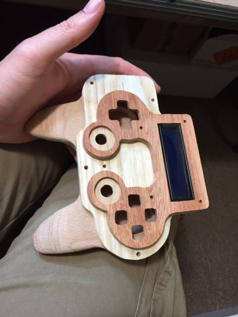
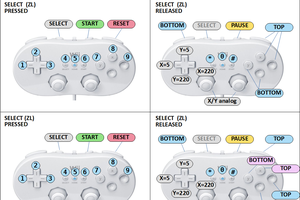
The controller uses a simple protocol, which allows an application (robot, etc) to configure exactly what is desired.  The robot can request to enable / disable joysticks and buttons, and can adjust the poll frequency and maximum analog transmit rate.

You can download complete source code from http://public.digitalcave.ca/source/psx_controller_source.tgz .  This will compile using the command 'make', using a recent AVR GCC compiler and associated build tools.  I have built this on OSX and Debian Linux without problems.

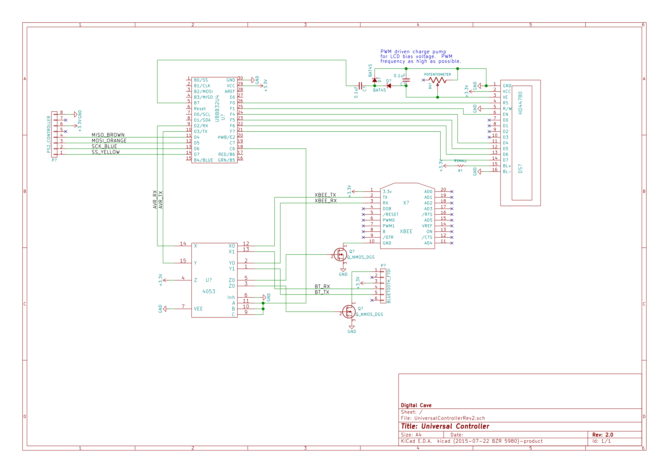
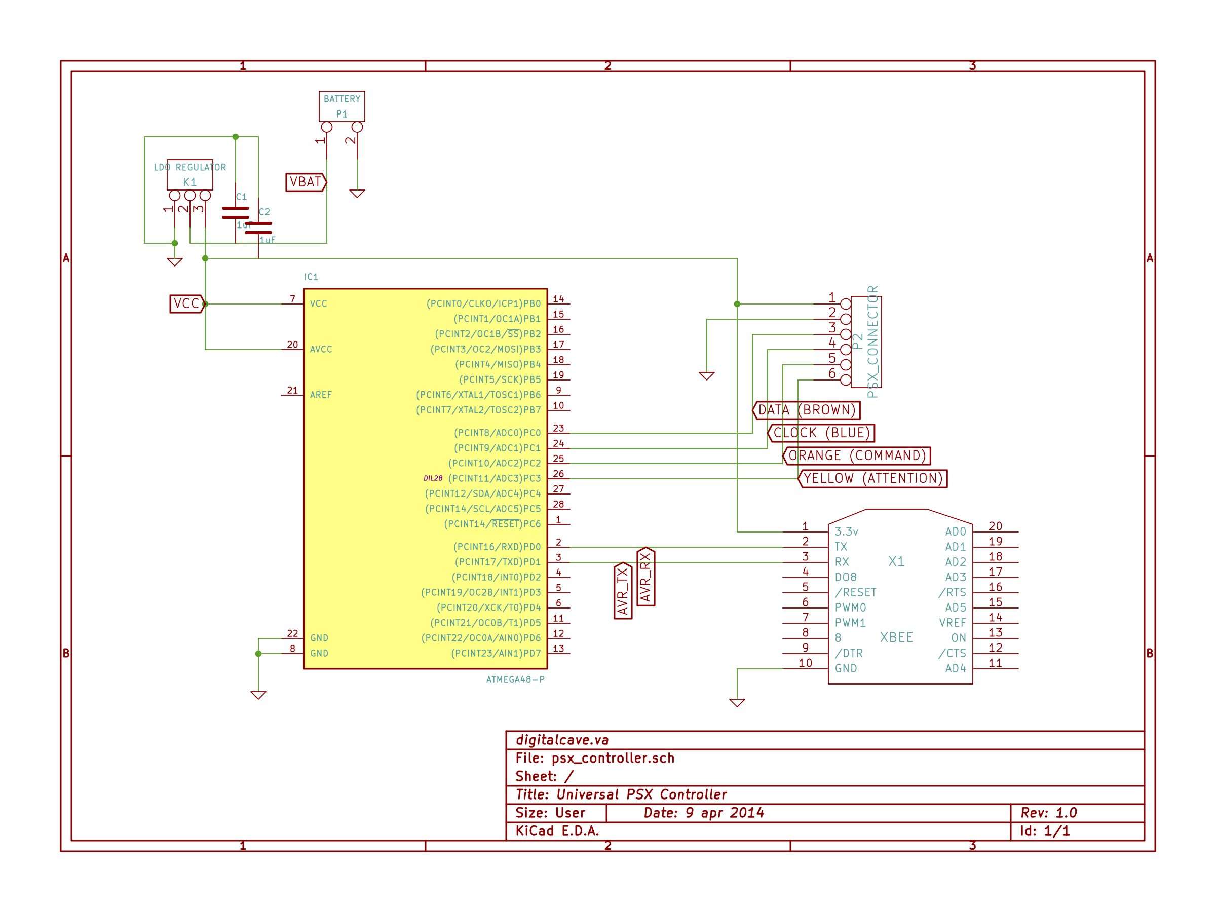
As part of this project, I wrote a PSX library for AVR GCC which allows you to bit-bang commands to and from the PSX.  The PS2 controllers actually use a version of SPI (clock polarity and clock phase are 1), so in theory you could use the SPI hardware on an AVR to talk directly to the controller.  However, I chose to do a bit-banging protocol because a) I want to use the SPI pins for other things, b) this is more portable to other AVRs (and in fact other micro controllers in general).  Plus, the actual SPI implementation is just a small part of the library; the protocol communicating on top of SPI is more difficult (well, more obscure... there is nothing really hard there, but you need to know the message formats).  For details on the PSX library component, please see http://digitalcave.ca/resources/avr/psx.jsp

This controller is currently used in two of my robotics projects: a quadcopter (Chiindii), and a hexapod (Stubby), and i am planning on using it for additional builds in the future.

  • 1 × PS2 Controller WYSIWYG: just a plain-jane, old school PS2 controller. Found mine in the thrift store for $5
  • 1 × ATMega48 Microprocessors, Microcontrollers, DSPs / ARM, RISC-Based Microcontrollers
  • 1 × XBee (or whatever radio serial link you have on hand) By far the most expensive part of this system, but I had one from a previous project
  • 1 × 3v LDO Voltage regulator
  • 2 × 1uF Ceramic Caps Required for the specific LDO regulator I am using

View all 7 components

  • Rev 2 Completed

    The Big One02/18/2016 at 02:21 0 comments

    Rev 2 is now (mostly?) completed. I have added an FTDI Bridge mode, where you can plug the controller into a computer and forward bytes from the wireless interface to USB and vice versa. I'm sure there will be some more adjustments to software in the coming weeks (to better support #Chiindii quadcopter), but hardware is completed (and has been for some time, I have just been lazy in documenting it).

    A question you may ask is, what version to make? Rev 1 or Rev 2? The answer is 'it depends'.

    Rev 1 is much easier to replicate, and is fully compatible with the official Stubby code.

    Rev 2 takes a lot more custom work, custom PCBs, and hacked-together wiring. Furthermore, it is not completely compatible with Stubby (the framed serial protocol that it speaks is the same, but some of the messages being passed are different), plus it is missing some buttons that the real PS2 controller have.

    In short, I would suggest making Rev 1 unless you have a good reason to do otherwise (notably, the need for a throttle control or display).

  • Bluetooth link working

    The Big One09/30/2015 at 16:28 0 comments

    Last night I put in the Bluetooth radio. I have decided to change to a physical DPDT switch rather than a multiplexer, since the MUX that I have on hand is a DIP version and is too large to fit into the case properly. (If I were designing a board for this, it would be no problem to use a SMD one, but deadbugging a DIP is way too large).

    Next step is the XBee radio, and then we are just about done the hardware portion.

  • Stuffing Junk into a Case

    The Big One09/25/2015 at 15:49 0 comments

    I did some soldering last night. So far I have the PS2 controller circuit board, the UBBB32u4, the LCD display, and the boost power supply all soldered together and in the enclosure (which can still close). Still outstanding is the sliding pot, the radios, and the multiplexer. I am starting to get a bit nervous about fitting both radios and multiplexer into the enclosure... I suppose that if I need to, I can just put one radio in. I would like to get both if possible, though... oh well, we will see what happens.

    Below are some pictures of the project so far (the front buttons are not installed here, as they were drying from a coat of stain that I just put on).

  • Rev 2.0 Schematic

    The Big One09/23/2015 at 17:53 0 comments

    Yesterday I put the finishing coat of Danish Oil onto the new case, and put the original PS2 controller PCB into the top part of the case. I also finished up the (hopefully) final touches to the schematic. (While I am not planning on making a PCB for this, it is complicated enough that I do want a schematic, even though the implementation will just be on perf board).

    The design allows for two radios (XBee and Bluetooth HC-06). Which radio is to be used will be selected by a 3-circuit binary analog multiplexer, which will switch power, Rx, and Tx.

    Also included in the schematic is the charge pump which allows me to run the 5v LCD at 3.3v by providing the required negative bias voltage.

    Still outstanding is making the supporting circuit on perfboard, updating the software to take advantage of all this, and actually fitting the entire thing together.

    Enjoy!

  • New Case WIP

    The Big One09/17/2015 at 01:51 0 comments

    I have most of the case designed, and partially completed. It is made from multiple layers of 1/4" wood (various types), with holes cut for the different components. Pictures of what I have so far are below:

  • New Case + Features

    The Big One08/27/2015 at 15:50 0 comments

    After a long period without changes, I have decided to add some new features to the Universal Controller. I will be adding a display (so that the device being controlled can send messages, debug text, etc); a buzzer for alerts (low battery, etc); and a slide potentiometer for absolute position detection for things like throttle position. I plan on using 2x AA batteries with a boost regulator instead of the 3x AAA batteries + linear regulator that I am using currently.

    I am also going to be ditching the plastic case and making a custom enclosure out of wood.

    These changes should make the system more usable for some other devices, most notably a quadcopter that is currently in planning phases.

    More details to follow once I actually make some progress.

  • Bugfixes after Protocol Change

    The Big One09/08/2014 at 03:21 0 comments

    If you have a Universal Controller, and you have taken the recent protocol changes, please pull the latest code and redeploy.  There are a couple of bug fixes which I have just pushed which, while quite simple, can make a large impact on how the thing works.

    Bugs fixed include:

    • Analog joystick change value mask should be 0xFC, not 0xF7
    • MESSAGE_ANNOUNCE_CONTROL_ID should be sent every 2 - 3 seconds, not the ~10 minutes that it was previously (8 bit overflow vs 16 bit overflow actually makes a bit of difference... who'd have thunk it!)

  • Major changes to protocol

    The Big One09/03/2014 at 02:42 0 comments

    I had to think long and hard about whether it was a good idea to do this or not.  One of the major goals in the Universal Controller was to keep things as simple as possible.  Having all messages fit within one byte definitely helped this goal: there was no need for framing, escaping, checksums (I am assuming the link layer, XBee, keeps things sane here), etc.

    Unfortunately, life is not simple.

    While working on changes for Stubby to allow more fine grained programmatic control from a computer, I started running into limitations with the one byte messages.  A major problem was that I had completely used the bit space; I had no spare messages which I could use to inform Stubby which controller was talking to it.  Furthermore, I wanted the ability to send debugging information such as battery levels, etc (which is going to especially be needed when I start working on an RC airplane controlled by this Universal Controller... sometime... probably next year, once the Hackaday Prize is completed).

    To alleviate this problem, I implemented a relatively simple bi-directional multi-byte protocol.  This is included as a library for the AVR, and so can be used by multiple projects (and in fact I am already using this library in both Stubby and the Universal Controller).  A single message in this protocol consists of the following sections:

    • Start of Frame (1 byte, constant value 0x7e)
    • Length (1 byte) (includes command byte but does not include checksum byte)
    • Command (1 byte)
    • Payload (0 - 254 bytes)
    • Checksum

    In the library itself, there are a number of commands defined for common things (ACK, EnableDebug, DisableDebug, RequestBattery, SendBattery, etc).  These are all in the range 0x00 - 0x0F.

    In the Universal Controller implementation, there are other commands defined.  These include things like ButtonPush, ButtonRelease, JoystickMove (for allowing the controller to push state to the client) as well as things like SetPollFrequency and SetAnalogFrequency (to allow the client to configure the controller).  All of these commands are in the range 0x10 - 0x1F.

    So, in order to use the Universal Controller to control Stubby, both must be compiled from the code committed after today (September 2 2014).  I sincerely apologize for any inconvenience, especially if you are using it to control other projects.  If you have questions about how to implement this protocol support on the client side, please feel free to email me and ask.

    Cheers

  • Slight Change to Protocol

    The Big One04/24/2014 at 01:00 0 comments

    We made a few tweaks to the protocol today, in an effort to make things easier to implement on the client side, with fewer special cases.  In addition, we created a client.h file in lib/universal_controller/client.h, which provides various #defines to simplify implementing the client side code.

    The new protocol is as follows:

    Sending button / stick events (from controller to client): 
    
    
    Bit order:
    [TAAVVVVV] (analog stick event)
    [TN0SBBBB] (button event)
    
    Bit 8 (T, MSB): 0 == analog stick message, 1 == digital button message
    
    Analog stick message:
     Bit 7 (A)  : 0 == Left stick, 1 == Right Stick
     Bit 6 (A)  : 0 == X axis, 1 == Y axis
     Bit 5::1(V): Analog stick value: For the Y axis, 0x00 is all the way forward and 
                  0x1F is all the way back; for the X axis, 0x00 is all the way left 
                  and 0x1F is all the way right.
    
    Digital button message:
     Bit 7 (N)  : 0 == Normal button press / release event, 1 == No Buttons Pressed event.
                  When bit 7 is 1, the remainder of the message is ignored.  By convention
                  we fill buts 6::1 with zeros in this state, meaning that the 'No button
                  pressed' message will always be 0xC0.
     Bit 6      : Unused, set to 0
     Bit 5 (S)  : 0 = Released, 1 = Pressed
     Bit 4::1(B): Button number.  Use lib/universal_controller/client.h for defines.
    
    Receiving client commands (from client to controller):
    
    Bit order:
    [CCXXXXXX]
       C: Command (see below)
       X: Command-specific message, left padded with zeros
    
     Commands:
       00: Enable / Disable Buttons
         [000AAAAX]
          A: Button address.  Specify a button to modify (0x00 - 0x0F).
          X: New value.  1 = enabled, 0 = disabled
       01: Enable / Disable Analog Sticks
         [0100000X]
           X: New value.  1 = enabled, 0 = disabled
       10: Set poll frequency (non-changes will be re-sent after this time)
         [10XXXXXX]
           X: New poll value, to be shifted 8 bits left and set in OCR1A.
              For instance, to set OCR1A = 0x0F00 (the default value), you would send the
              value 001111 (0x0F) as shifting this 8 bits gives 0x0F00.
              0x0F (expanded to 0x0F00) results in an idle poll time of about 500ms.
              0x3F (expanded to 0x3F00) results in an idle poll time of about 2s.
              0x01 (expanded to 0x0100) results in an idle poll time of about 10ms.
              0x00 results in completely disabling idle polling (only send change events).
       11: Set maximum analog repeat frequency (you can't send analog stick changes faster than this).
         [11XXXXXX]
           X: New poll value, to be shifted 2 bits left and set in OCR0A.  Analog values cannot be sent until          this compare ISR fires.  Set this high enough to not be sending un-needed data constantly, 
              but low enough that you can get good response times from the controller.
              0x3F (expanded to 0xFC) is the maximum, and results in an analog repeat time of about 32ms.
              0x10 (expanded to 0x40) is the default, and results in an analog repeat time of about 8ms.
              0x00 results in completely disabling the timer and sends all analog events, no matter how fast.


    The client.h file includes the following defines:

    //Bit 8: 0 == analog stick message, 1 == digital button message
    #define CONTROLLER_MESSAGE_TYPE_MASK	0x80
    #define CONTROLLER_MESSAGE_TYPE_ANALOG	0x00
    #define CONTROLLER_MESSAGE_TYPE_BUTTON	0x80
    
    //Bit 7 (Analog): Left / Right stick
    #define CONTROLLER_ANALOG_STICK			0x40
    #define CONTROLLER_ANALOG_STICK_LEFT	0x00
    #define CONTROLLER_ANALOG_STICK_RIGHT	0x40
    
    //Bit 6 (Analog): X / Y axis
    #define CONTROLLER_ANALOG_AXIS			0x20
    #define CONTROLLER_ANALOG_AXIS_X		0x00
    #define CONTROLLER_ANALOG_AXIS_Y		0x20
    
    //Bit 5::1 (Analog): Value
    #define CONTROLLER_ANALOG_VALUE_MASK	0x1F
    
    //No Buttons Pressed message
    #define CONTROLLER_BUTTON_NONE			0xC0
    
    //Bit 5 (Button): Press / Release
    #define CONTROLLER_BUTTON_PRESS_MASK	0x10
    #define CONTROLLER_BUTTON_RELEASE		0x00
    #define CONTROLLER_BUTTON_PRESS			0x10
    
    //Bit 4::1 (Button): Button...
    Read more »

  • Communicating with a PS2 Controller

    The Big One04/09/2014 at 22:17 0 comments

    PS2 controllers are actually pretty easy to interface with; they use SPI mode 3 (CPOL=1 and CPHA=1); while in theory you could use the SPI hardware on an AVR to talk directly to the controller, I chose to just write my own (adapt my own) bit-banging protocol.

    There are a few good sites which have protocol details; in our library, we started with Bill Porter's Arduino library, and adapted it to work with raw AVR-GCC rather than requiring Arduino.  

    Over time, I ended up re-writing much of the code (both because I could, and also to make the timings a bit closer to spec).  The PS2 protocol details as described at http://store.curiousinventor.com/guides/PS2/#high_level were invaluable to this project; just because the hardware uses SPI, doesn't mean that it understands what you are sending!

    In its current form, our PSX library provides a simple API for communicating with PS2 controllers.  It allows for reading of all 16 buttons (everything other than the 'Analog' button, which is a special function), as well as 8 bit values for X and Y axis on both joysticks.  It does not handle button pressures or vibration motors, but it would be relatively simple to add support for that if you are interested in it.

    For details on the PSX library component, and to download the code, please see http://digitalcave.ca/resources/avr/psx.jsp

View all 12 project logs

  • 1
    Step 1

    Disassemble PS2 Controller.  Remove vibration motors (this is where the AVR / XBee will reside).  Cut the controller cable which plugs into the actual console; this is no longer needed (depending on the layout inside the controller, you may be able to reuse a portion of this cable for step 2).

  • 2
    Step 2

    Solder wires onto the Blue, Brown, Orange, and Yellow wires, plus GND / VCC (Red and Gray).  Solder to a 6 pin female header.  (Or, if you have enough room inside the controller, you can use the last couple inches of cable, and just solder this directly to the 6 pin female header).

  • 3
    Step 3

    Solder up the AVR + regulator onto a perf board, according to the schematic.  Include programming headers (MOSI / MISO / SCK / RESET) and a 6 pin breakout for the PS2 controller wires you soldered last step.

    The schematic for this is below:

View all 5 instructions

Enjoy this project?

Share

Discussions

basic2point0 wrote 04/11/2014 at 01:20 point
I have found a couple Logitech PS2 wireless controllers in thrift stores that might for this. They're a little larger than the stock controllers and they have a battery compartment.

  Are you sure? yes | no

The Big One wrote 04/11/2014 at 01:59 point
Very interesting... that is one thing I am not happy about, namely requiring an external battery pack. It works fine, and it feels great in hand, but it doesn't look very professional.

I wonder if the wireless controllers use the same SPI protocol, or if they have some proprietary setup? (I assume they have a dongle on the console side to translate the wireless signals into what the console is expecting?)

Cheers

  Are you sure? yes | no

basic2point0 wrote 04/11/2014 at 20:18 point
They do have a receiver that plugs into the PS2 controller port. Not sure about anything else at the moment. I had problems with them losing the signal when I reset the console, so I quit using them. Now they're in the spare parts box, waiting on their next life.

  Are you sure? yes | no

The Big One wrote 04/09/2014 at 19:07 point
Look in thrift stores... I got mine for $5 a couple years back, and I see them all the time when I browse around. :-)

  Are you sure? yes | no

Eric Evenchick wrote 04/09/2014 at 18:27 point
It took me a minute to figure out why you modified the controller. Then I realized that you crammed the whole circuit in there. Definitely makes for a nicely integrated build.

It took some digging through your site, but that protocol appears to be pretty easy to work with. I want to find some old PS2 controllers now...

  Are you sure? yes | no

Similar Projects

Does this project spark your interest?

Become a member to follow this project and never miss any updates