 Jan
JanDesigning a PCB is hard work (if you can't decide...)
I very quickly had all of the loggers features written down and began choosing components.
From that moment on, it kicked in: creeping featurism. And let me be clear: I DON'T want that nor do I need that. It's just always the case when I start creating a PCB.
I just wanted to track 3 temperatures and humidity plus maybe brightnes. But NO, let's add this let's add that. So creating the layout took me way longer than I'd like to admit...
After a while I thought to myself: f*#!? it, I need to get that board ready by april, bees ain't got no time fo that! So I decided to throw out lots of headers, parts and features and get to the really basic functions and board I needed:
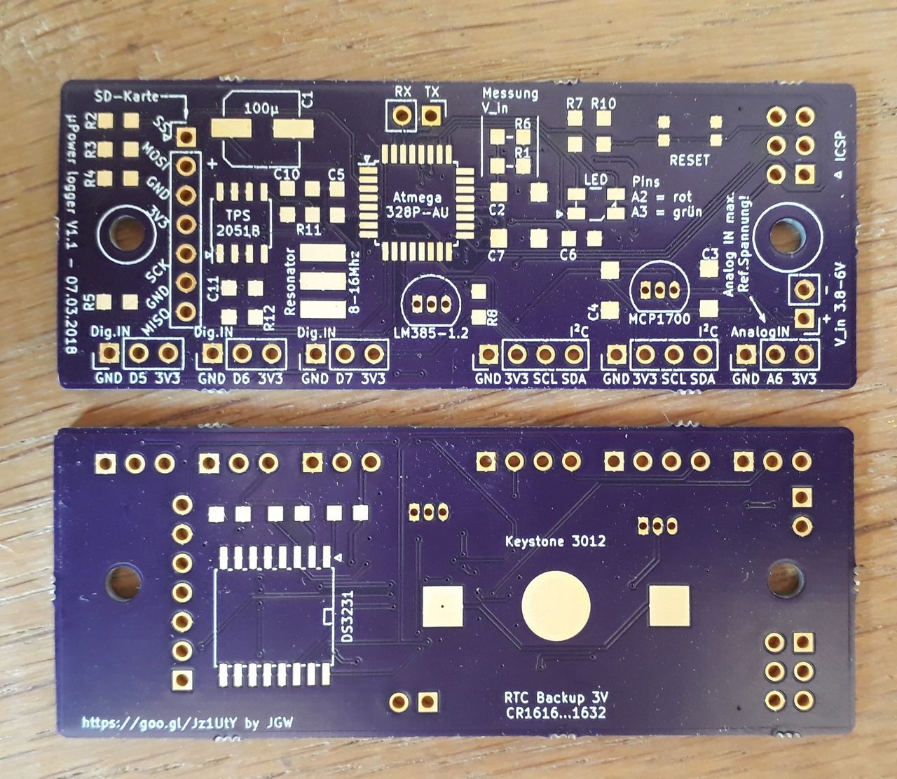
The board arrived after a wait time of just 2,5 weeks (USA-Germany). Amazing! Quality is just top notch, as well as the service. I ordered a wrong version, just mailed them my mistake and a few hours later that order was canceled and my money refunded. I will definately order again @oshpark !!!
You may wonder about that strange way to add the micro SD card. It's a method I like for prototyping and breadboarding and I had no micro SD sockets at hand.
So I chose the angled pin headers to micro SD adapter route.
The SD card can be (dis)connected to the 3V3 rail by a high-side switch to save precious microamps while the card is not used.
Everything else is pretty straight-forward: MCP1700/1703 regulator, a two-color signal LED, DS3231 for timekeeping, battery holder for backup.
I've also added a LM385-1.2 for a precise reference voltage to the AREF of the Atmega. More on that approach later on...
Errors in the PCB
I checked everything before sending the gerbers to OSHpark, but a few things went unnoticed. Those were easily fixed but anyway, don't forget these things:
- AVCC needs to be conneced to VCC of the Atmega. Otherwise you won't be able to operate. Just forgot that connection in the circuit... Fixed by a short piece of wire to VCC.
- the ground pad for the coin cell needs to be bigger. Solder stop mask is higher than the pad. Fixed by adding a bit of solder!
- make pads large enough for good heat transfer. Those MCP and LM385 pads are too damn small...
Other design "fails"
Not an error but the DS3231 is powered directly from the MCP1700 in this revision. It consumes up to (haven't measured it) 0,3mA. In my next board run the chip is going to be pin-powered by the Atmega.
Discussions
Become a Hackaday.io Member
Create an account to leave a comment. Already have an account? Log In.