 Voja Antonic
The enclosure was made exactly as it was described at http://hackaday.com/2015/06/03/how-to-build-beautiful-enclosures-from-fr4-aka-pcbs/, so I have nothing to add about it. It is more interesting for me how we built DC units then. There were no switching regulators then, so we used transformers, Graetz bridges and electrolytic capacitors.
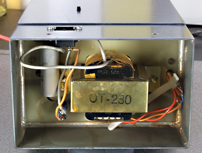
Probably I thought that I shall cut that cable tie later... and so it's still waiting. It must be the most patient cable tie ever.
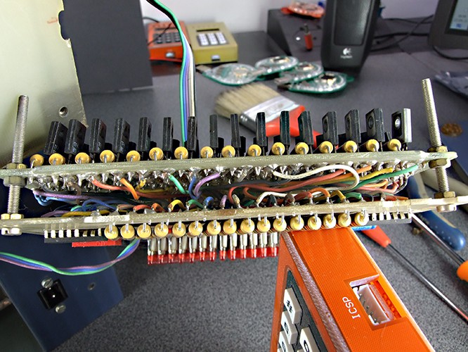
Here is the hand-made front PCB with LED matrix, row drivers, 7445 decoders (row scan was used) and BD136 column transistors.
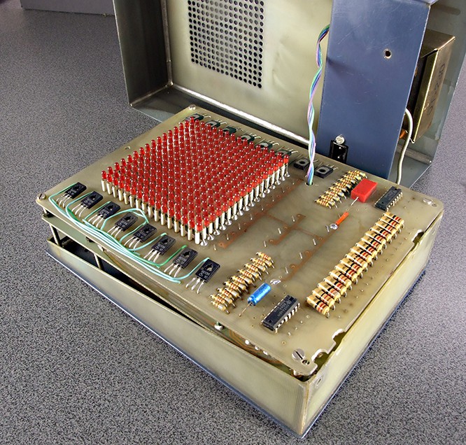
Linear regulator 7805 was the product of the cutting edge technology at that time, so it was used here. It could not supply a lot of current, so LED matrix was supplied from the unregulated source (probably from the electrolytic capacitors).
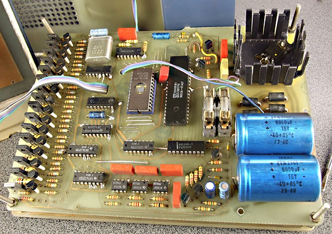
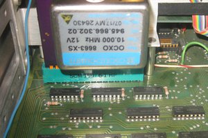
Here you see Z80 CPU, 2716 EPROM and column darlington driver group (BD135's with some small signal NPN transistors). The most interesting thing is the random generator: it was built of three 555's (at the bottom), running at different frequencies - you can see 15K, 22K and 10K timing resistors. Those signals were XORed in software, to generate one random bit.
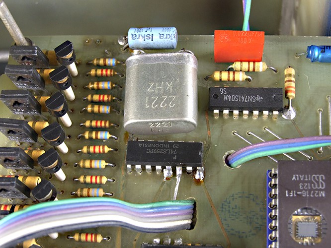
Do you remember how we built oscillators in 1980's? We used 74LS gates with 910 Ω feedback resistors, and 330 Ω pull-up which Z80 required, ac the Clock input was the only Non-TTL signal. Oscillator frequency was 2.221 MHz, which is quite strange, but that was probably the only Quartz that I had at the moment.
I'm not proud of the interconnection - only wires, no connector. Only screws, no spacers. Obviously, I had to learn a lot in those days. (please ignore the surrounding items - it's just my table)
After all, I can say that it worked for 35 years at my desk. I moved exactly 7 times, and each time I took the special care of it. Jus a few scratches, but not a single screw nut was replaced! Even the EPROM still keeps its contents. I don't have the source file, maybe it's time to make the backup copy?


 ksk
ksk
 BaumInventions
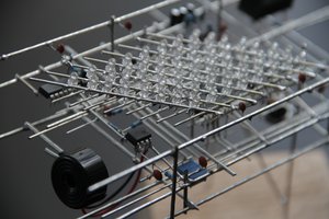
 tomcircuit
Ha that's great; thanks! I can practically smell that "old electronics" smell.
In passing; wWhen googling "Graetz bridge" (oh! you mean bridge rectifier! :-) - came across nice bit of trivia on the wikipedia page; "Some early console radios created the loudspeaker's constant field with the current from the high voltage ("B +") power supply, which was then routed to the consuming circuits (permanent magnets were then too weak for good performance) to create the speaker's constant magnetic field. The speaker field coil thus performed 2 jobs in one: it acted as a choke, filtering the power supply, and it produced the magnetic field to operate the speaker."
Yay old electronics :-)