 Arduino Enigma
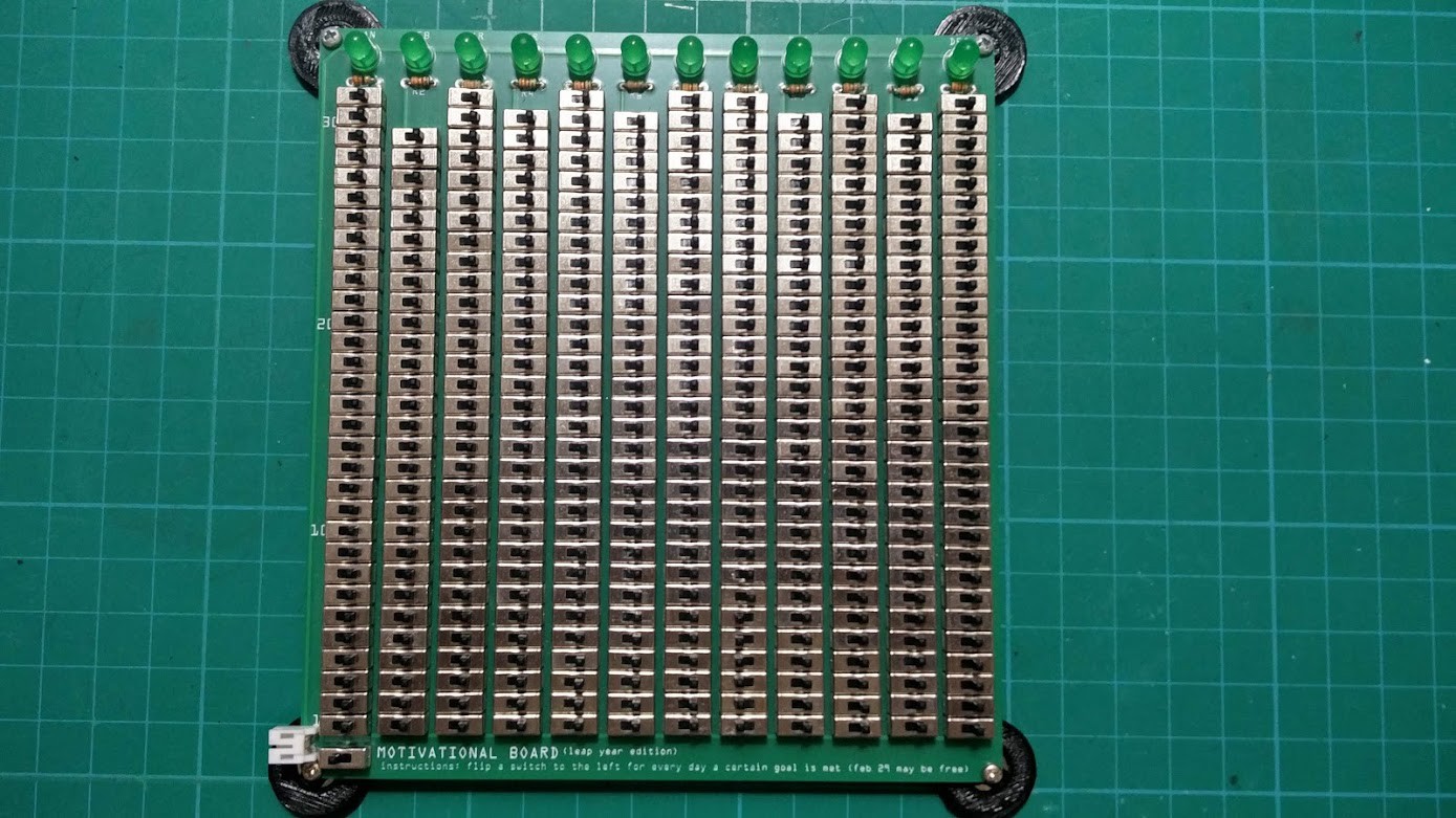
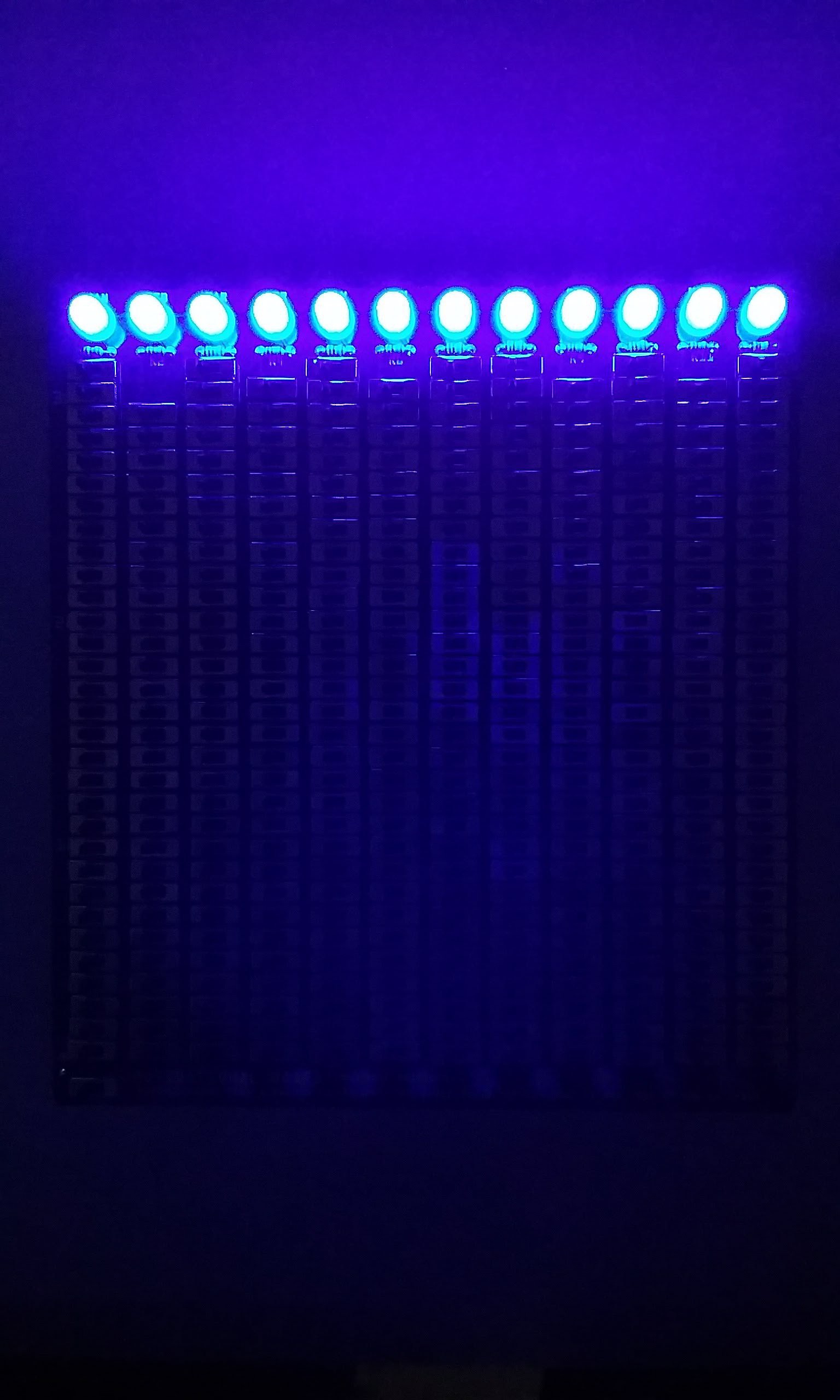
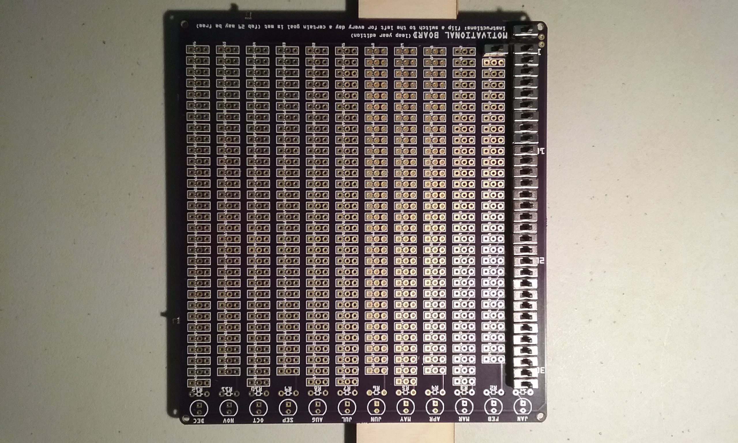
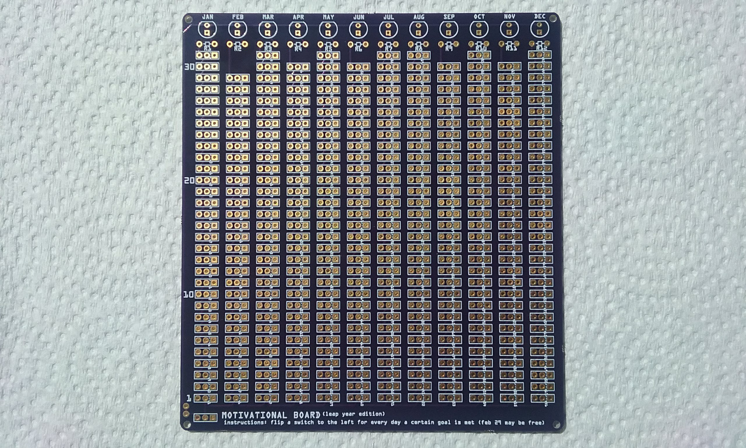
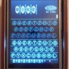
As a certain Thought Leader Life Coach says: "the best way to start a good habit is by doing it every day". This device will help you with that by tracking whether a goal has been accomplished that day or not and rewarding you at the end of the month by lighting an LED if the task has been performed every day of the month.
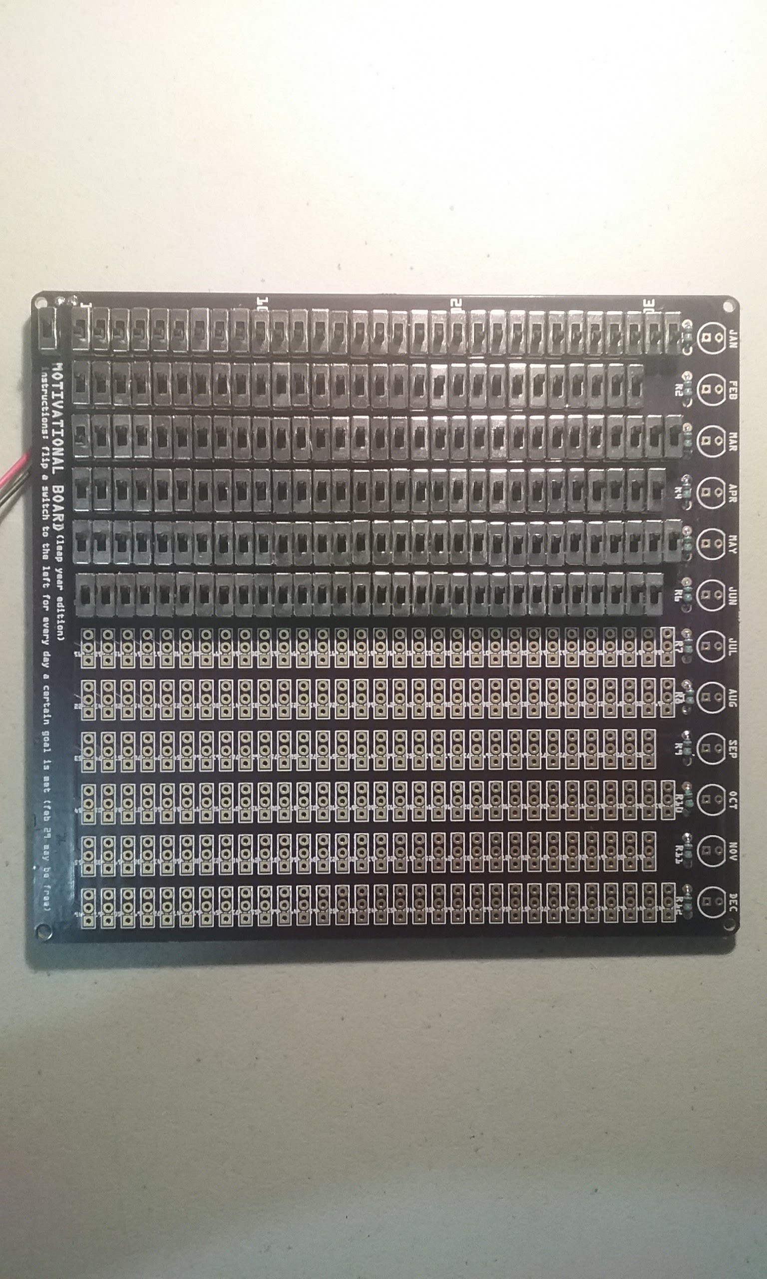
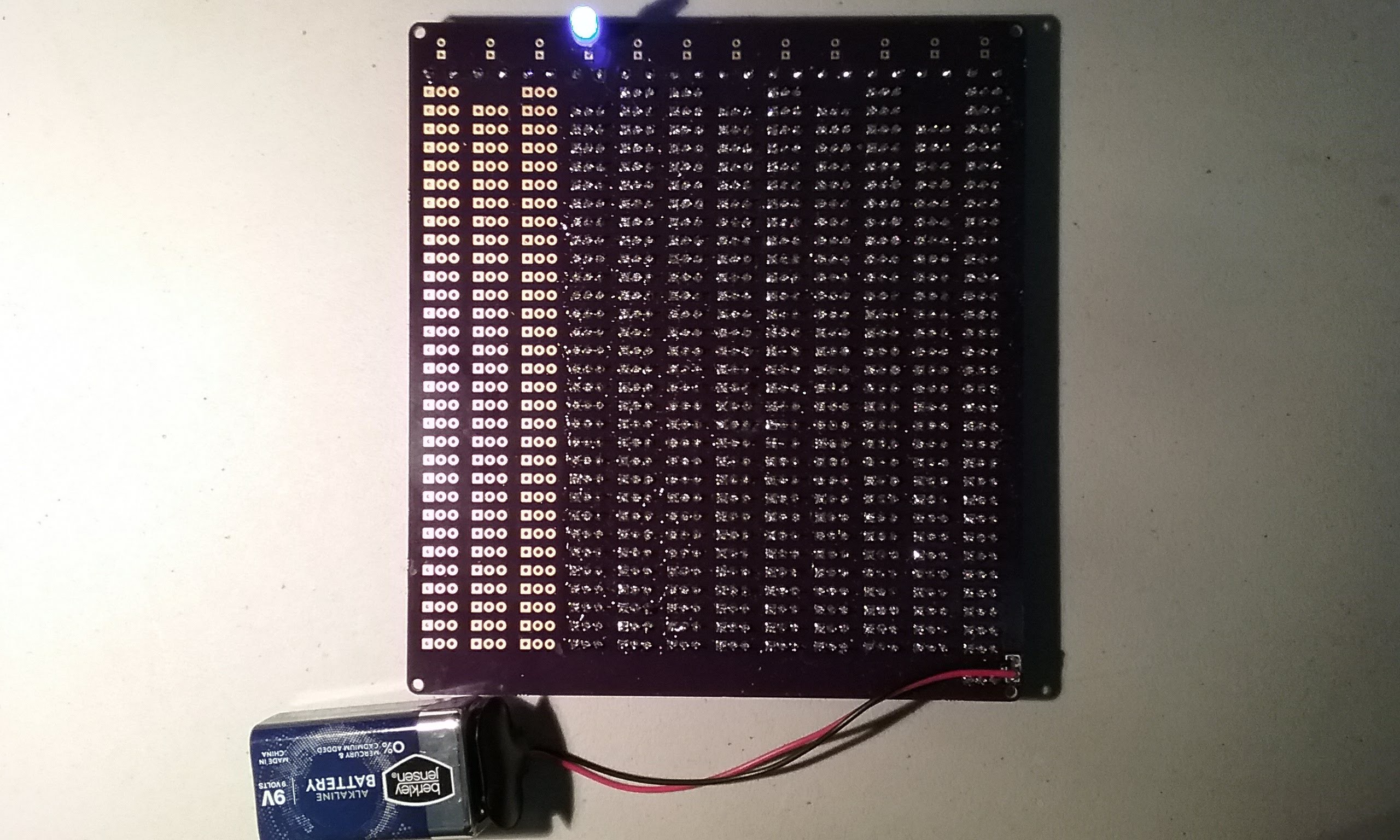
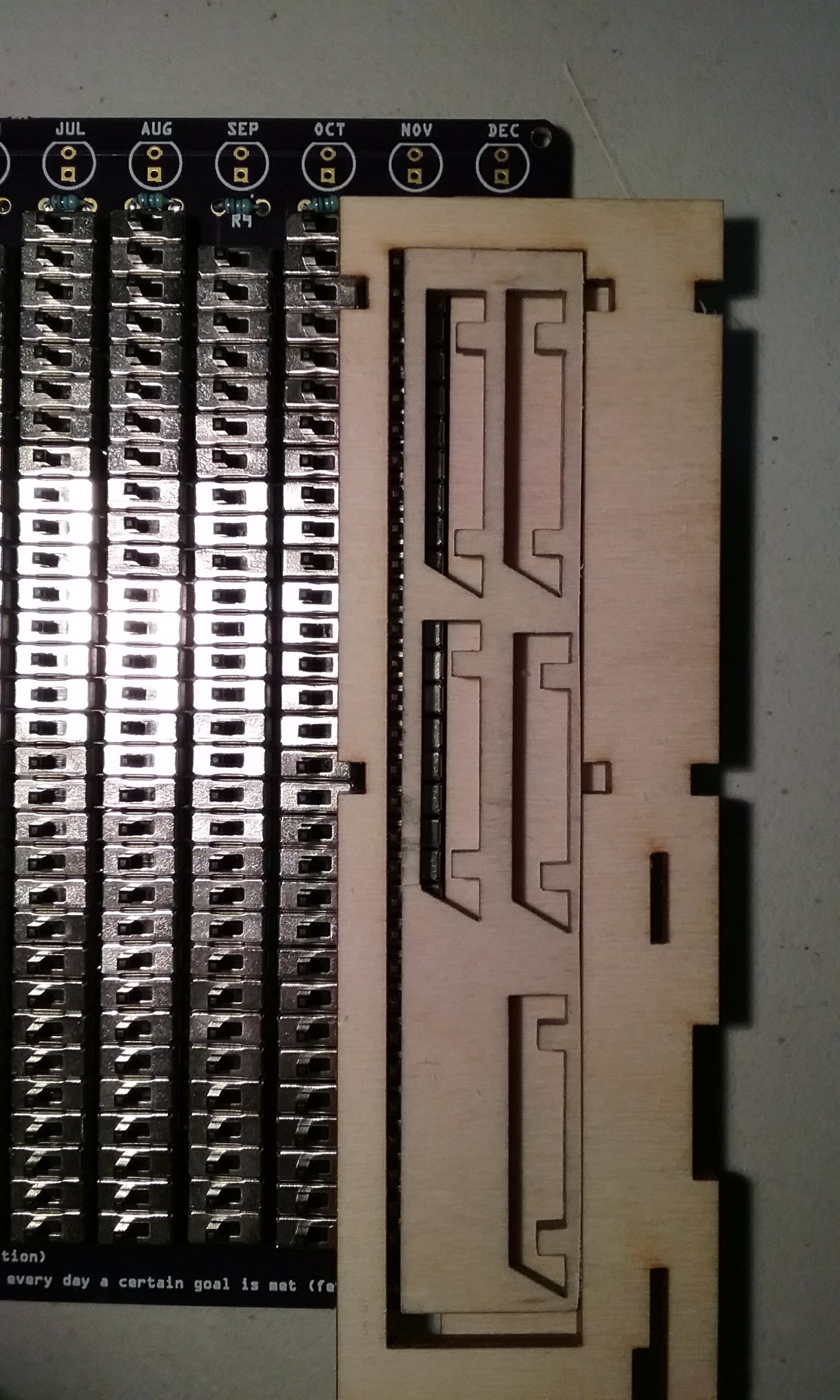
The PCB design makes assembling your own habit tracker easier by taking care of the connections between the switches. As this device reinforces an all-or-nothing mentality, it might be beneficial to work out some forgiveness arrangement in order to make it possible to make up missed days.
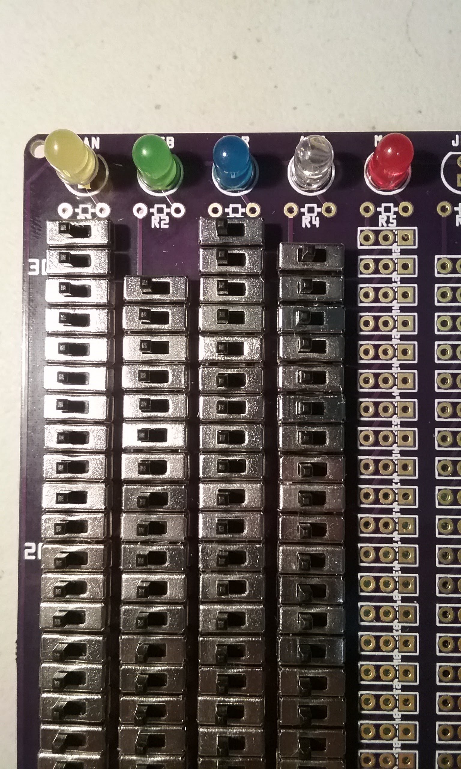
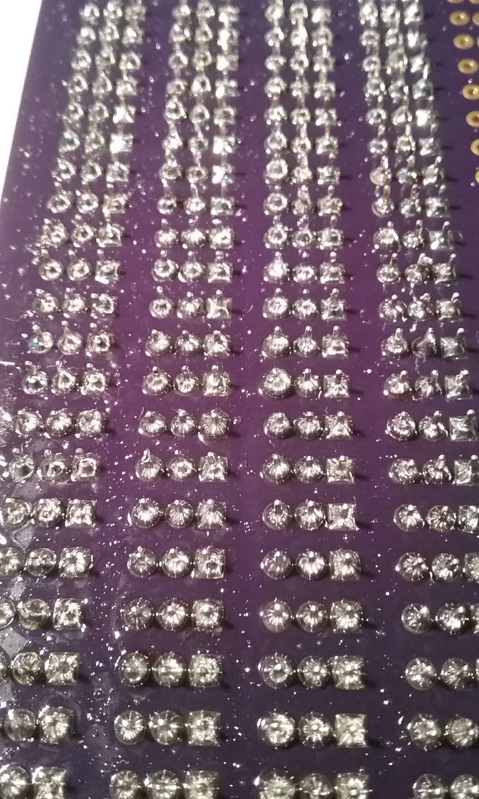
The schematic for this is simple. A power plug leads to a master on/off switch. The output of the master switch feeds the first switch in each month column. Each switch in a column is wired in series to the next. The last switch leads to a 1/8W resistor and an LED. The other leg of all the LEDS are tied together and return down the left side of the board to the power plug.
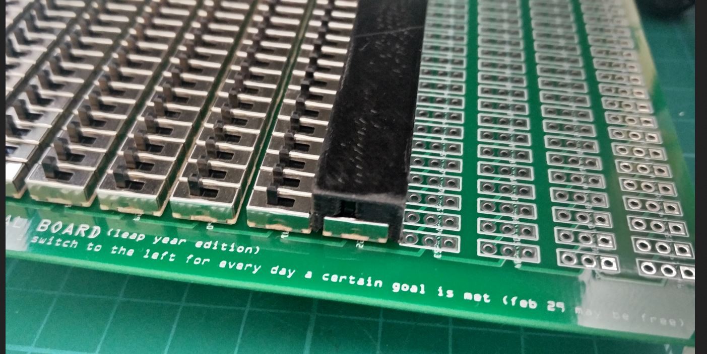
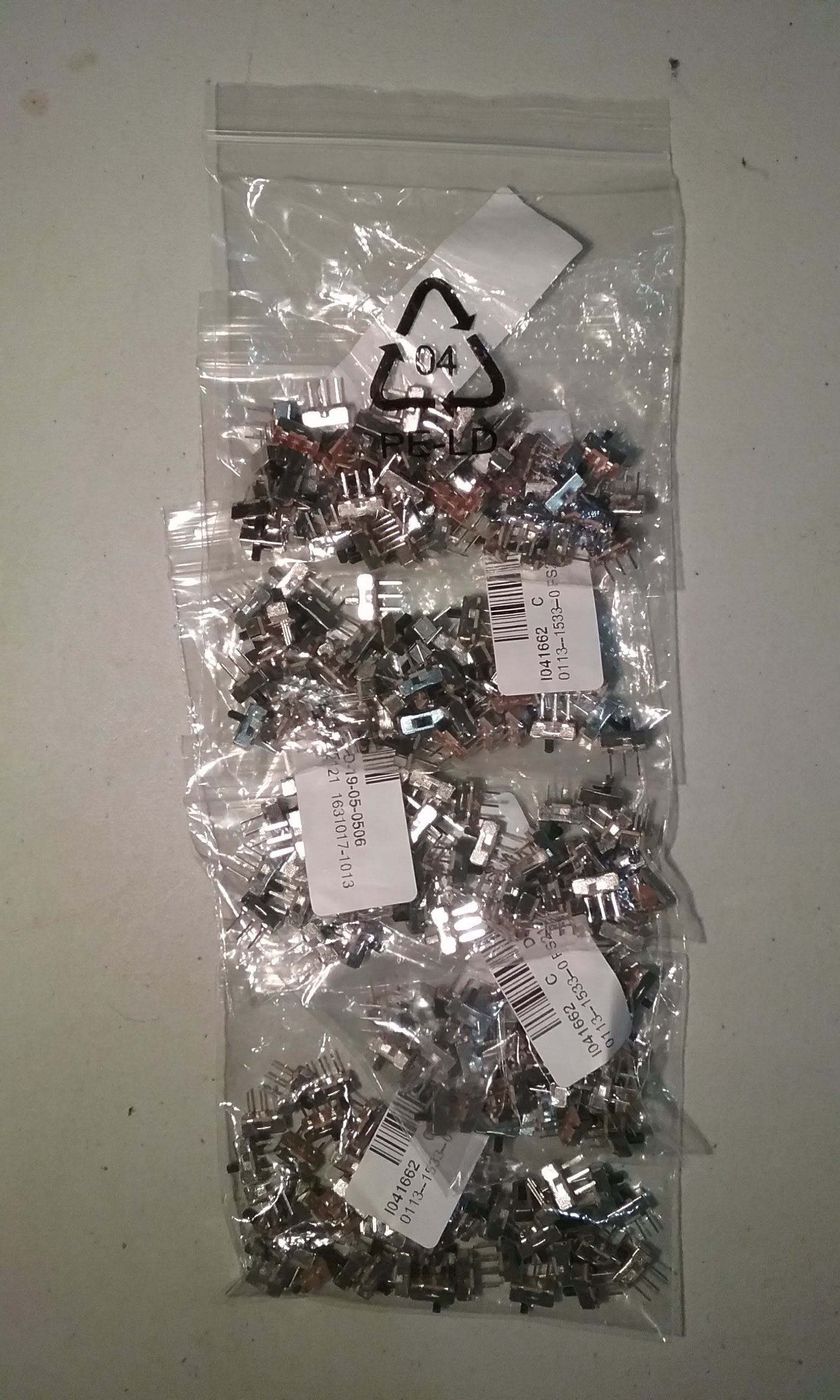
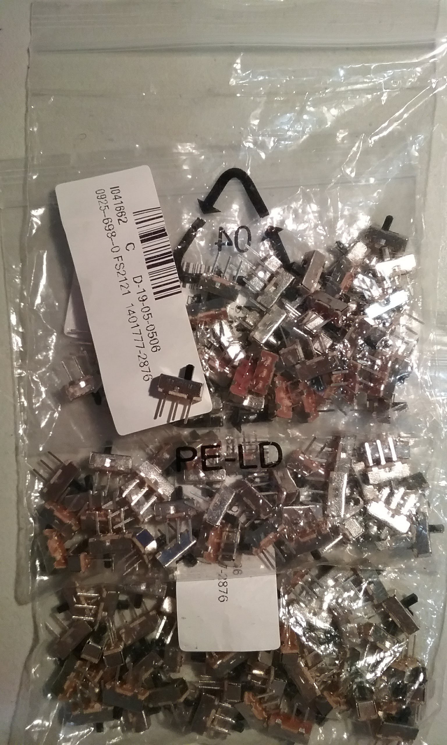
The switches were selected because that's what I was using for the Sinclair Scientific Calculator project and was familiar with them. The center pin is the common. If the stem is thrown to the left, the center and left pins are bridged. If the stem is thrown to the right, the center and right pins are bridged.
You can feed the switches from the left pin and get the output from the center or feed them from the center and get the output from the left pin.
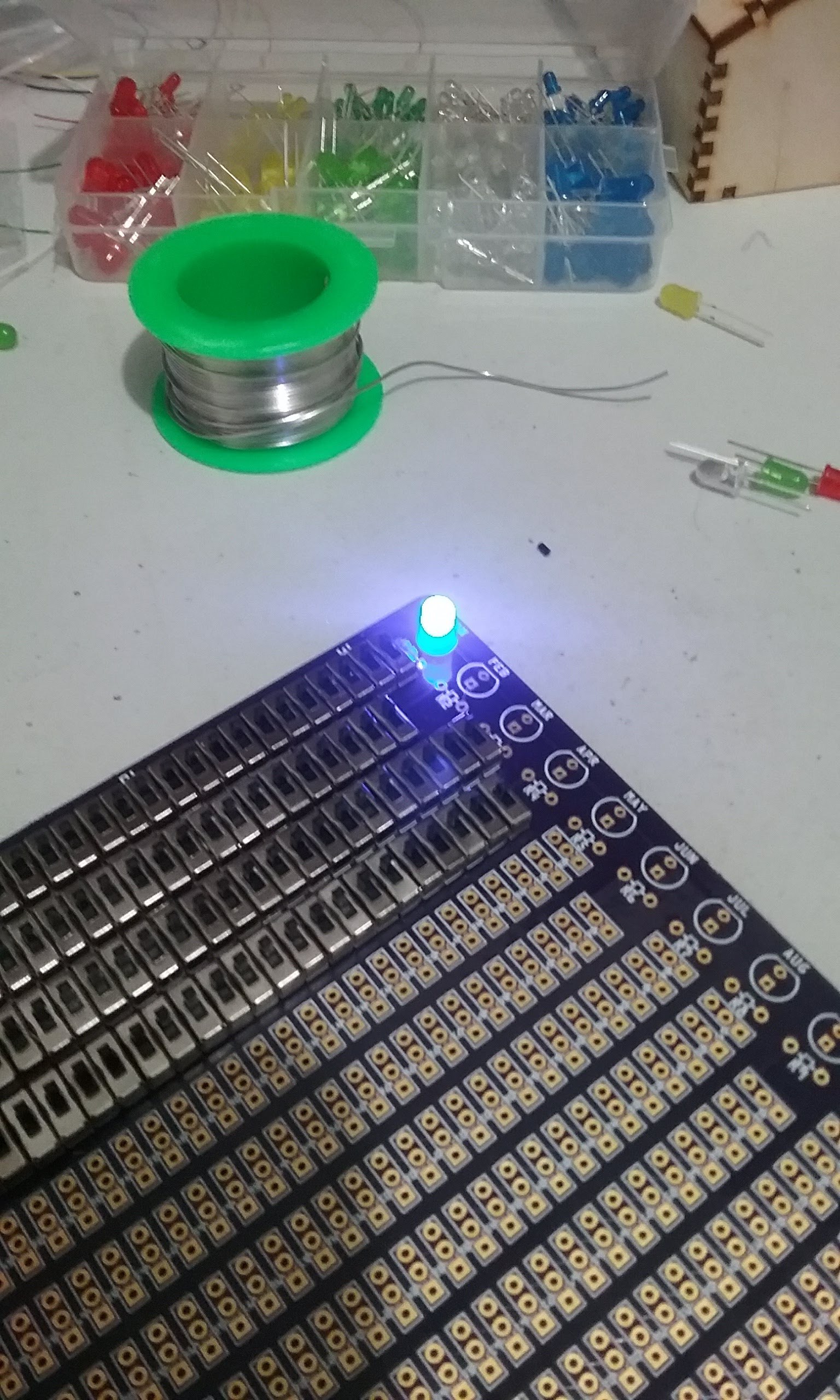
The polarity of the power plug is not marked. The supply voltage is not marked. The size of the resistor is not marked. The LED polarity is a suggestion. All of those details are left to the user. If in doubt, solder the master switch and a switch column first and then work out the details. I ended up selecting a 9V plug, 4.7K resistor and a blue led, because those are the things I had on hand.
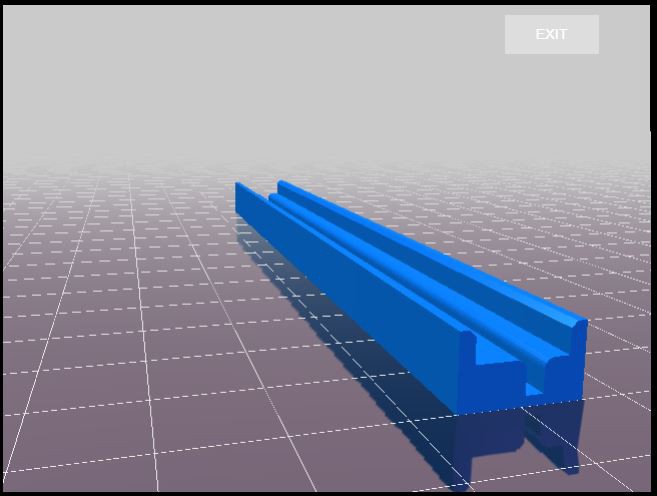
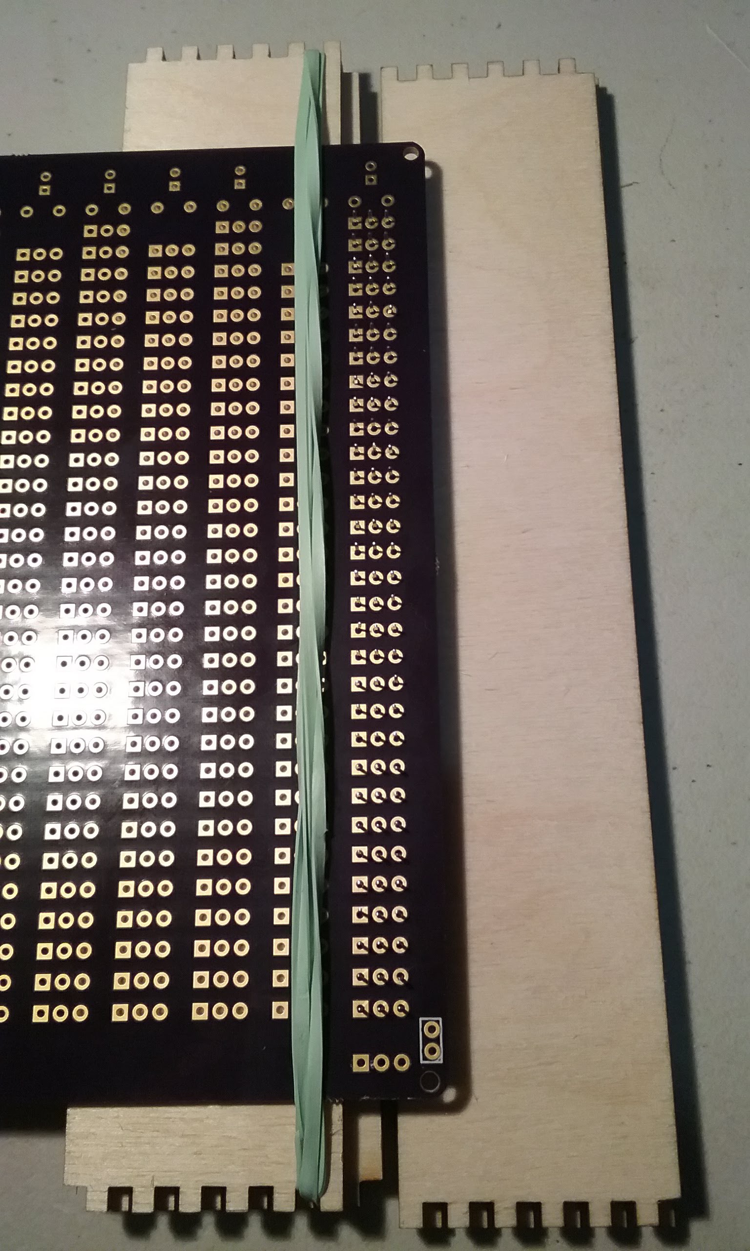
The next step is to design a laser cut base and alignment jig to grab all the switch stems.

Smaller Simone Giertz's Good Habit Tracker by @arduinoenigma is licensed under a Creative Commons Attribution-ShareAlike 4.0 International License.
Based on a work at https://www.instagram.com/p/BdZFs3MAqHR/.

Switch Alignment Jig by SamPerry is licensed under a Creative Commons Attribution 4.0 International License.

 theonetruestickman
 Sam Ettinger
 Jamie
Jamie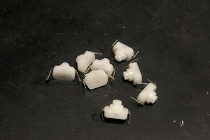
 Jeremy
you really did a great job to make this electric Honda object. i want to embed it with my homepage you can see here; https://friendfusion.net/