Close
0%
0%

USBreadboardIT

Breadboard-compatible USB PIC16F1455 board

Similar projects worth following
USBreadboardIT is a breadboard-compatible USB development board, based on PIC16F1455 8bit microcontroller from Microchip.
It can be powered from the USB host, at 5v or 3.3v (thanks to an on-board LDO regulator) or from an external power supply. It also sports a programmable LED and an on-board ICSP header.
The entire board, designed with KiCad, is contained in one square inch.

OSHW license!

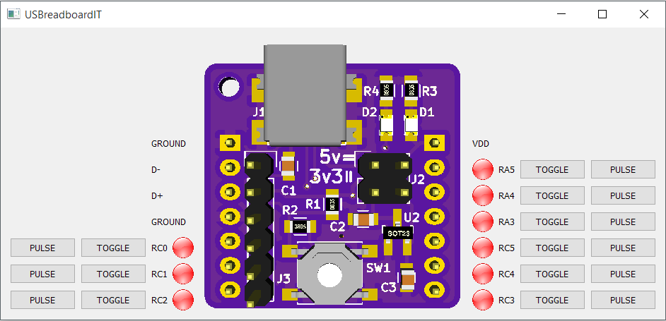
USBreadboardIT is intended to quickly prototype some simple USB-controlled systems on a breadboard, without having to write each time from scratch firmware and pc software. It offers GPIOs, as well as ADC, DAC and (maybe) SPI/I2C.

It can be used as well without PC control but having the ease of a USB bootloader to load the firmware.

The companion test firmware implements an HID interface thanks to m-stack by signal11 and can be controlled with any kind of HID API without the need to install a sppecific driver; the test software uses hidapi, also by signal11, and in particular its wrapper cython-hidapi with Python.

  • 1 × USB mini B connector Molex 0548190572
  • 1 × MCP1700T-3302E/TT Low Quiescent Current LDO - 3.3V output in SOT-23 package
  • 2 × 100nF 0805 ceramic capacitor
  • 1 × 100Ohm 0805 resistor
  • 1 × 10kOhm 0805 resistor

View all 14 components

  • BIGHID button

    WallaceIT06/12/2016 at 17:51 0 comments

    A simple application for USBreadboardIT is the BIGHID button (that is, a BIG HID button). It emulates an USB HID keyboard (so, no drivers) annd sends a single keypress or key combination, that can be bound to an usOr-defined action.

    It is based on two excellent pieces of software:

    The hardware part is very simple: a button is tied between a pulled-up input pin (RA3) of the board and GND. A USB cable is connected to corresponding signalls on the headers.

    The first software step has been performed uploading the DFU bootloader through a pickit2.

    Once the bootloader is working, connecting the usb cable to the PC while holding the button pushed exposes the bootloader to the OS and dfu-util can be used to upload code to the board.

    Code has to be compiled in MPLABX with the following options:

    --codeoffset=0x200
    --rom=default,-0-1FF,-1F7F-1F7F  

    Produced HEX file must be converted to proper dfu file through 454hex2dfu (included into bootloader repo):

    454hex2dfu MPLAB.X.production.hex hidkbd.dfu

    Then the obtained dfu file can be uploaded with

    dfu-util -D hidkbd.dfu

    The button has then to be connected and re-connected to start keyboard operation.

    The firmware polls RA and sends CTRL+SHIFT+1 when the button is pressed. OS bindings are then used to catch this combination.

  • Wrong pinout!

    WallaceIT06/11/2016 at 13:41 0 comments

    I noticed today that published pinout where not correct: USB D- and D+ pins were swapped in the image.

    Issue has been corrected.

  • Board is working!

    WallaceIT11/01/2015 at 16:47 3 comments

    Board is working! The classical blinky test past smoothly and now an initial version of the test - and maybe other usages - firmware is ready and uploaded on Github: Link

  • USBreadboardIT assembled and ready for testing

    WallaceIT10/26/2015 at 12:54 0 comments

    I assembled the first USBreadboardIT unit, completely by hand (have I mentioned that USBreadboardIT have been thought with hand-assembly in mind?). D1, that is the "power" LED tied to VDD, lights up when connected to power, so at least the power works, both at 5v and 3.3v :)

    Regarding the microcontroller, I used a PIC16F1454 because it's bigger brother PIC16F1455 (with analog capabilities added) was out of stock when I tried to order it. They are pin-compatible, so USBreadboardIT will work anyway.

  • PCBs arrived!

    WallaceIT10/26/2015 at 11:24 0 comments

    Wonderful purple PCBs arrived from OSHpark, time to assemble USBreadboardIT!

  • PCB sent to production! Plus test software

    WallaceIT10/08/2015 at 19:48 0 comments

    Yesterday I sent the PCB to OSH Park! It should arrive in one month (manufacturing plus shipping to Italy).

    I uploaded on Github the design files (kicad source plus gerber), together with a - unfinished - test application (written in python plus Qt) to control the board through USB HID.

  • Small board modifications

    WallaceIT10/05/2015 at 10:08 0 comments

    After some digging, I found an interesting USB bootloader fitting in only 512 words for PIC16F1455:

    https://github.com/majbthrd/PIC16F1-USB-DFU-Bootloader

    For this to work I have to add to the board a pushbutton on RA3 (the same pin as reset) and thus rrearrange the board a bit; after that I will send the board in production.

    Stay tuned!

View all 7 project logs

Enjoy this project?

Share

Discussions

alpha_ninja wrote 12/07/2015 at 00:53 point

[verified: no design files missing]

  Are you sure? yes | no

alpha_ninja wrote 12/02/2015 at 00:45 point

This is your one-week reminder to upload design documents: https://hackaday.io/project/7813-the-square-inch-project/log/28566-design-deadline

  Are you sure? yes | no

Jarrett wrote 10/09/2015 at 05:57 point

Dammit man, I just started working on almost exactly this!

  Are you sure? yes | no

WallaceIT wrote 10/10/2015 at 15:03 point

Well, it's because I invented some weeks ago the go-forth-in-time-and-steal-ideas-from-others-hackers-mind machine! But it doesn't fit in a square inch...maybe for the next Hackaday Prize? :)

  Are you sure? yes | no

Similar Projects

Does this project spark your interest?

Become a member to follow this project and never miss any updates