 Radu Motisan
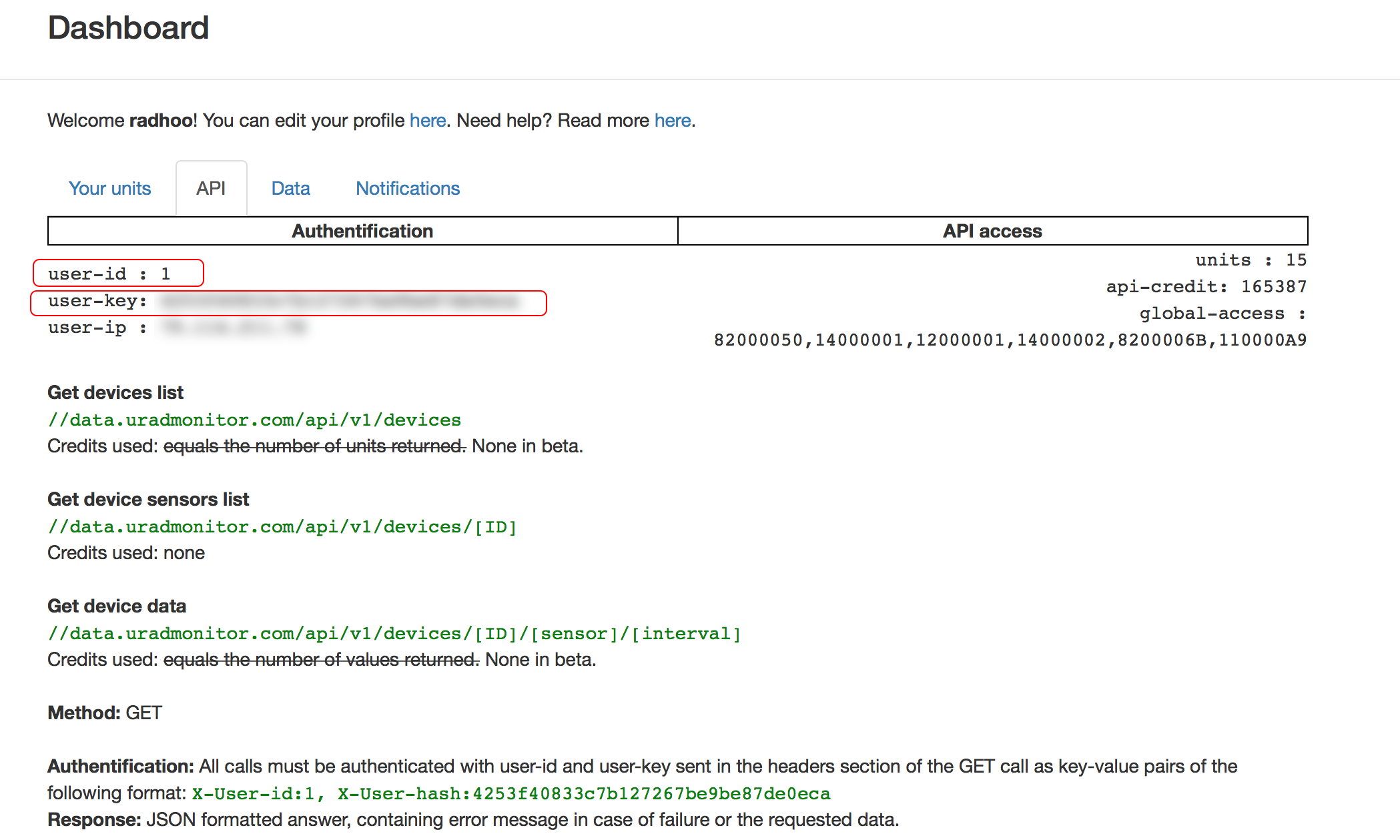
Intended as open source for those who want to build their own dosimeter with their own tools, this is an IOT device that can take several sensors and have the data centralised online. The readings are accessible via a RESTful API, or by connecting directly to the KIT1 unit, in the local LAN. This is useful when you want to monitor several locations, and plot charts or analyse the data.
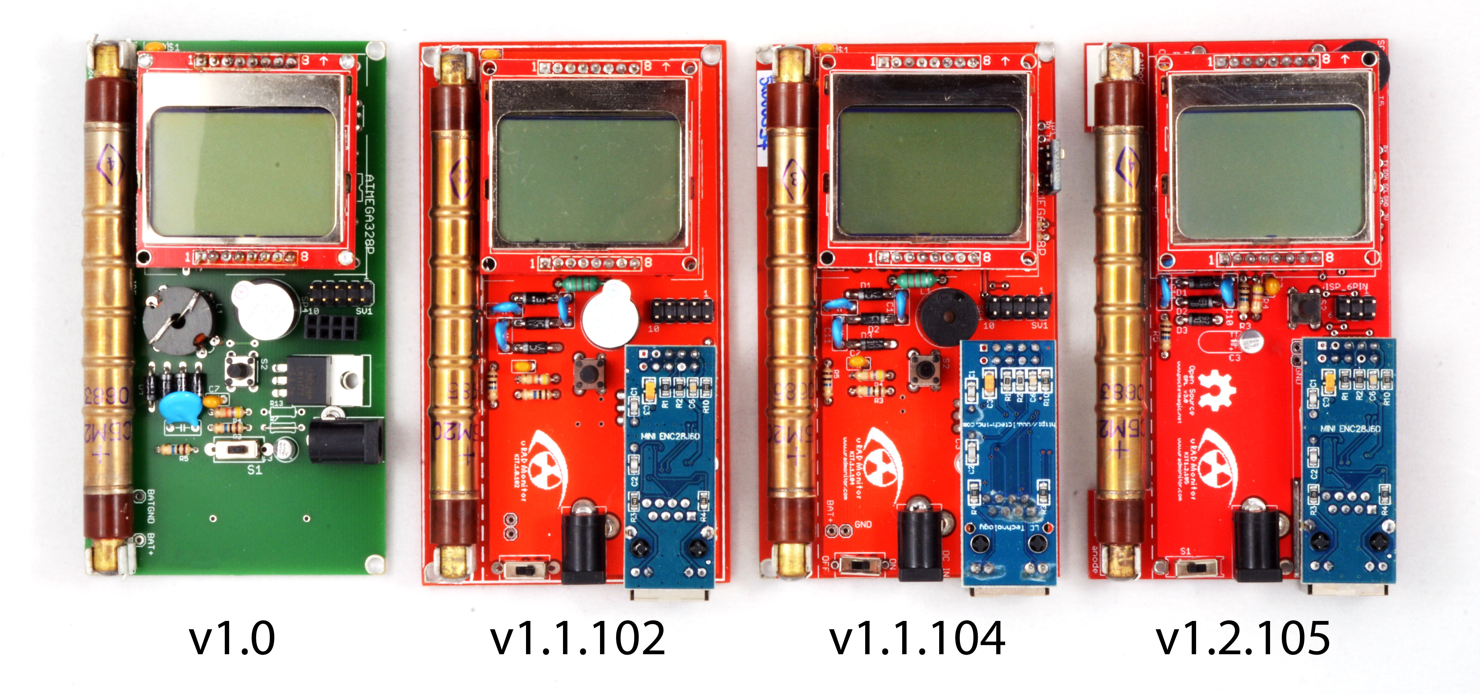
By default it comes with a SBM20 tube to measure Gamma radiation and has an extension slot (v1.2.105) to add additional sensors. The code on GITHUB offers support for the Bosch BME280 sensor by default.
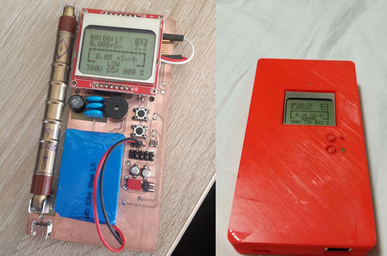
With the integrated Ethernet connectivity will send all measurements automatically via the Internet, to the uRADMonitor server, or to any backend you want. Add a battery and it can also be used as a portable dosimeter, showing all measurements on the LCD.
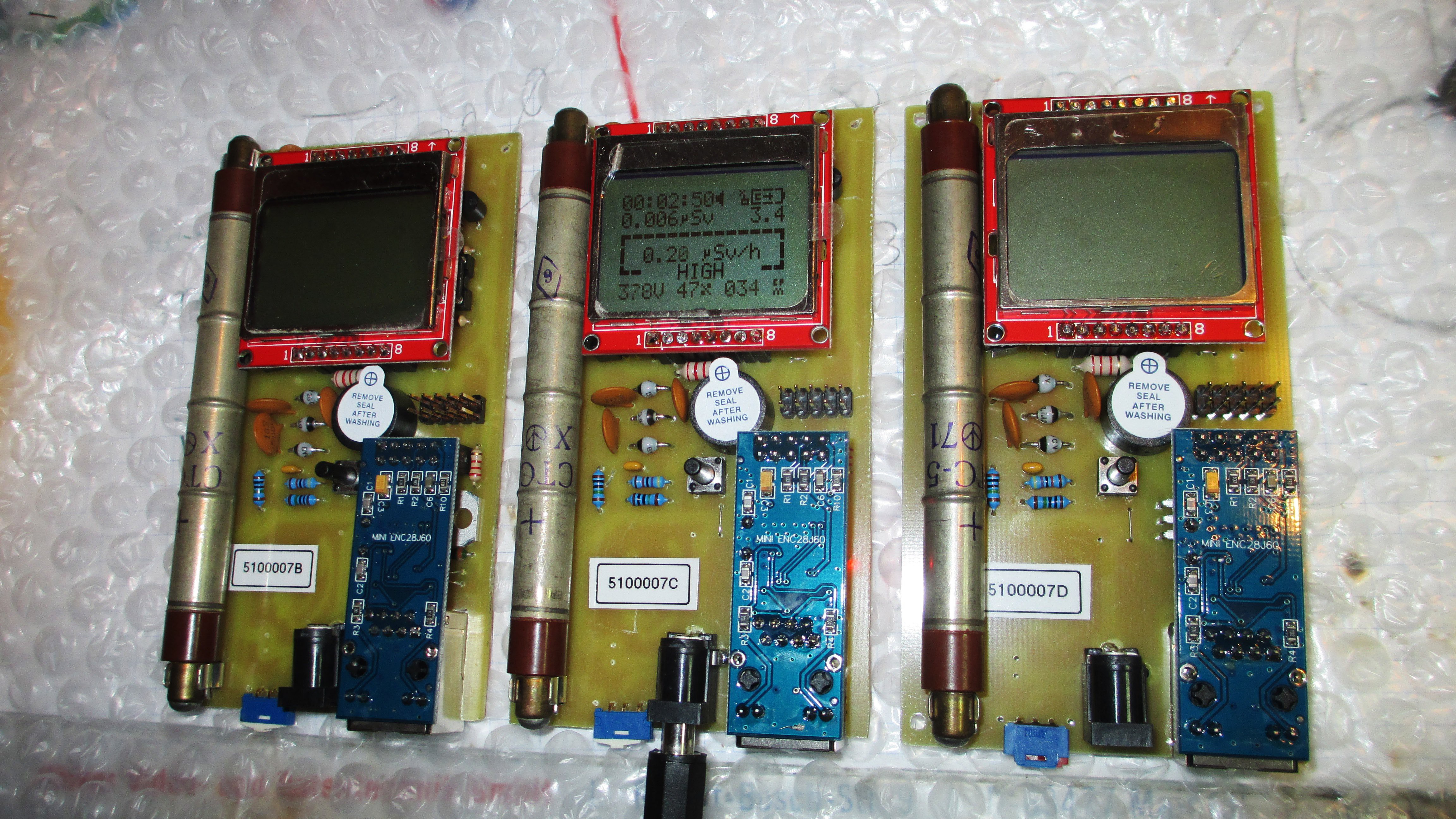
The community helped improving the design, with very many custom variants proving the utility of this IOT device, see the pictures in this project log.

Version 1.0
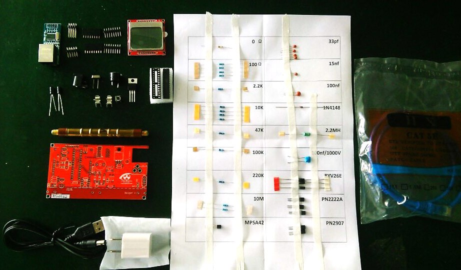
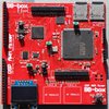
Finally an open source compact radiation dosimeter, that has an LCD and thus allows mobile use, but also comes with an Ethernet adapter so it can do radiation monitoring (uRADMonitorcompatible). This is a DIY Geiger Counter Kit, named the uRADMonitor KIT1, designed due to popular demand. Now, all those asking for a uRADMonitor Kit have a nice alternative in this device. This circuit uses a single layer PCB and only trough hole components, making the construction so much easier for all the DIY enthusiasts.
The video shows the first prototype of version KIT1.0, built using the toner transfer method. As said, it was designed using through hole components, on a single layer PCB board.
Version 1.1:
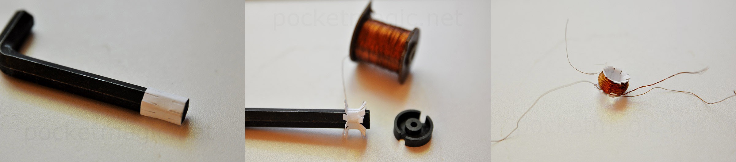
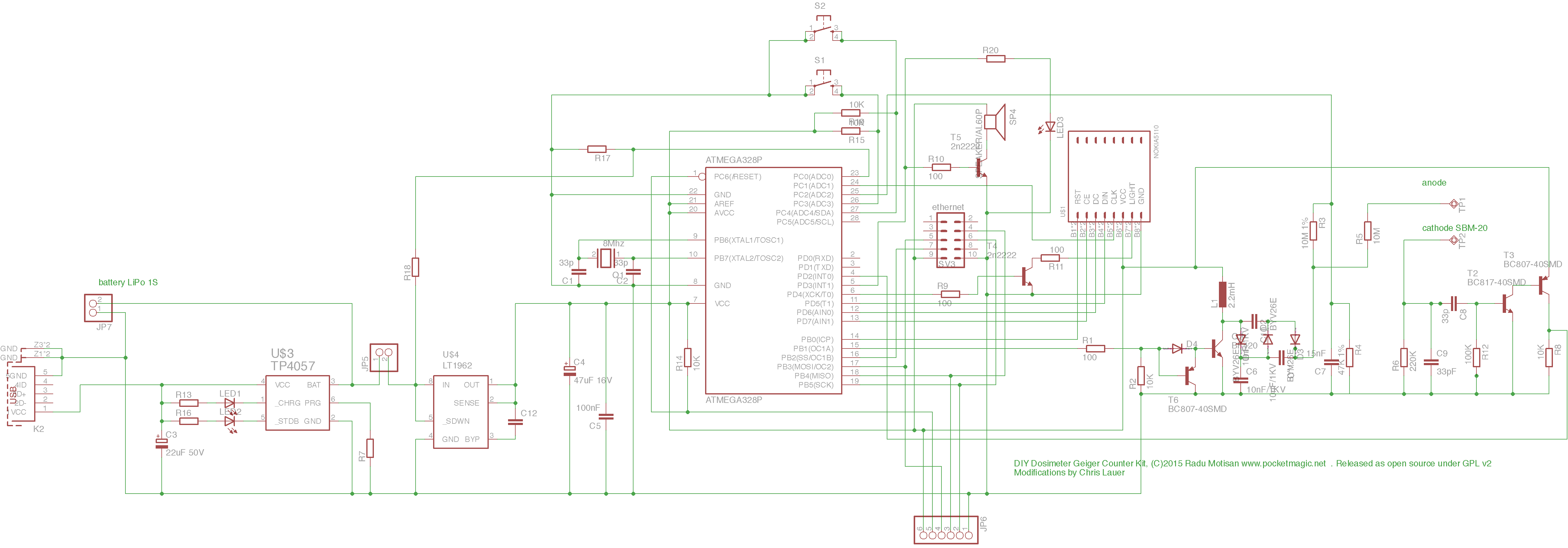
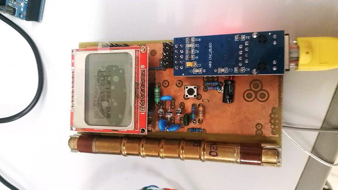
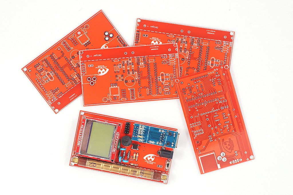
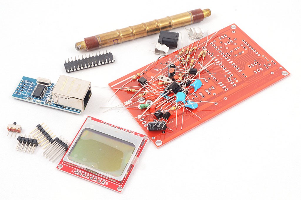
 What's new in 1.1 is that this revision replaces the ferrite transformer in the high voltage inverter, with a ferrite choke circuit, so the complicated part of building the custom transformer is gone. You can build this using shelf components, and the Gerbers files for making the PCBs are also included. Just send the gerbers to your favorite PCB manufacturer, get the BOM and start soldering. With just a couple of components, you'll have an excellent dosimeter of wonderful performance.
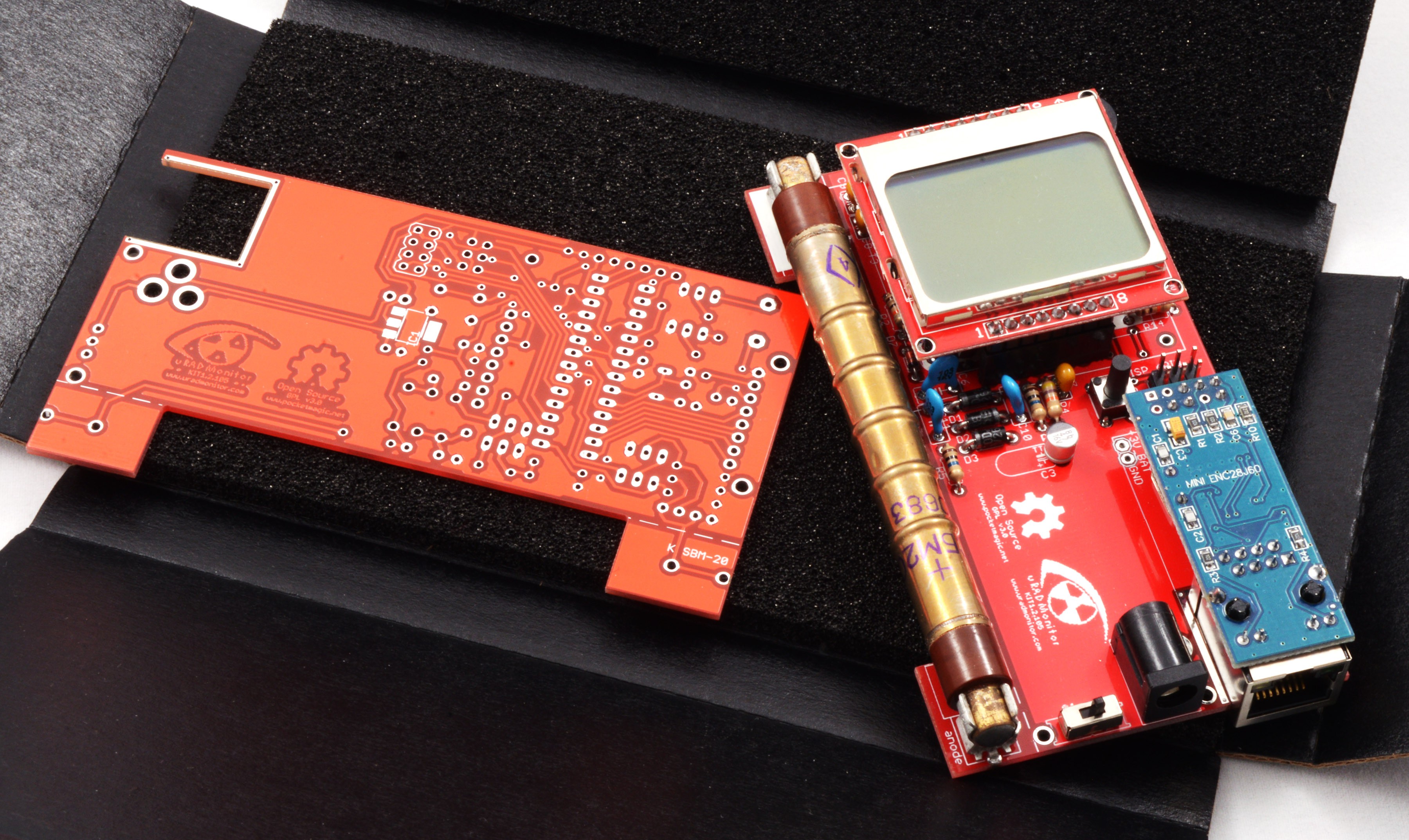
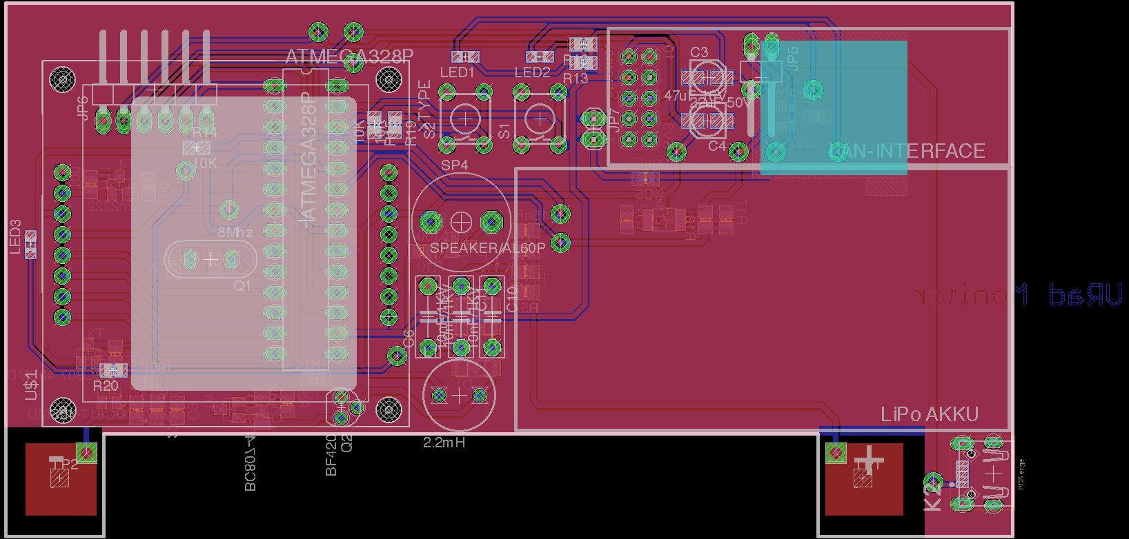
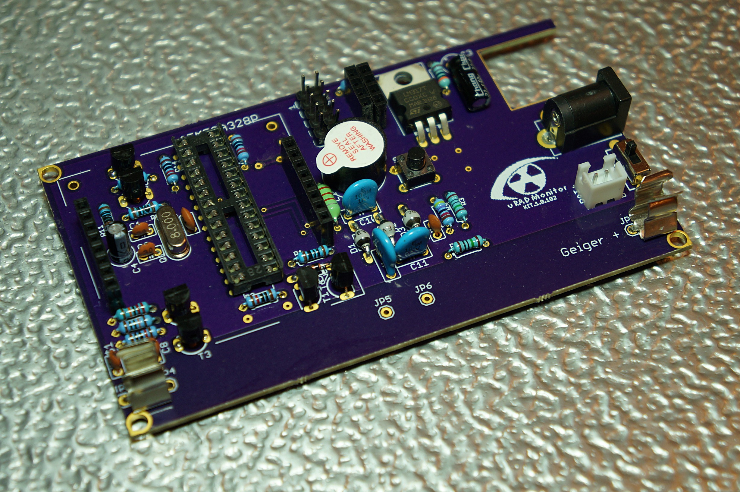
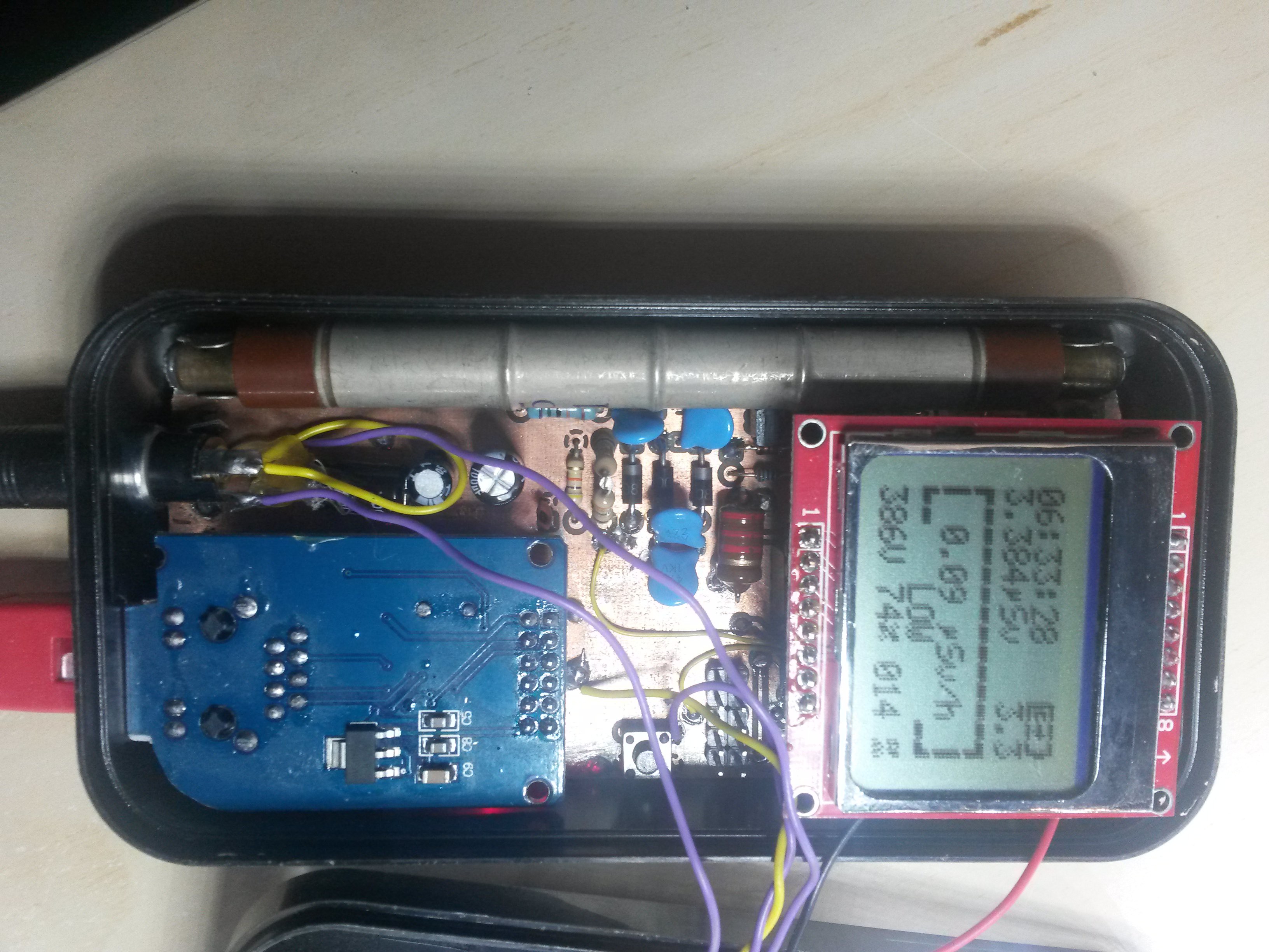
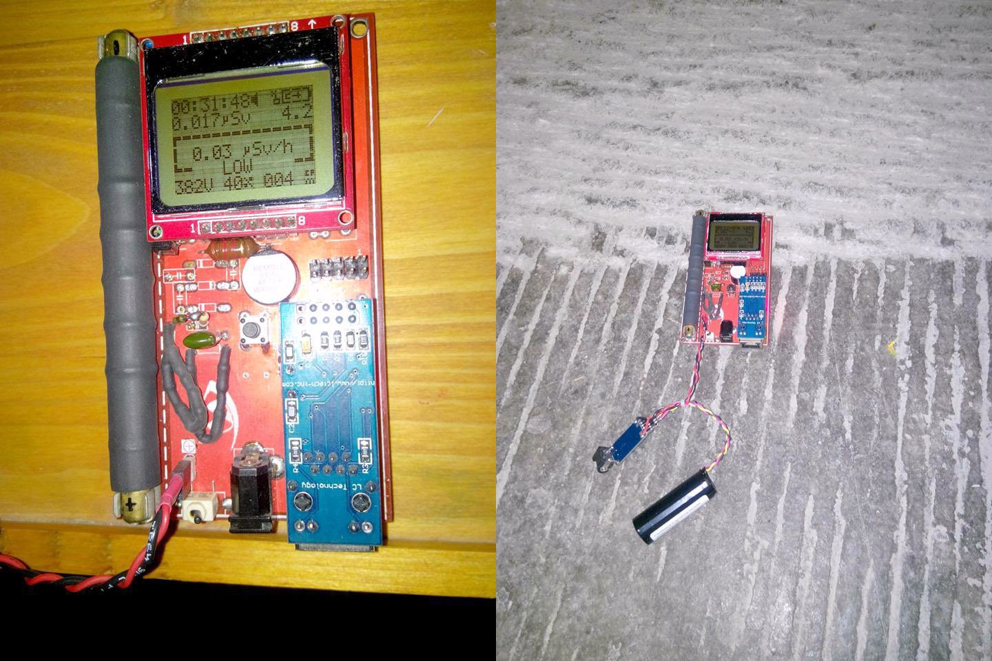
 There's a slot to mount a SBM-20 Geiger tube, a connector for the Ethernet module and one for the Nokia 5110 LCD screen. Both the LCD and the Ethernet adapter can be removed, allowing you to configure the final device: make that a portable dosimeter, a monitoring station or both. A speaker provides audible signals, including clicks and alarm, and a push button permits user interaction with the software. There are two pins at the bottom side that can be used to connect a 3V battery (two AA in series) or the unit can be powered using the DC connector, via a LM317 regulator and then it takes in any voltage in the 5-9V interval. The entire board runs on 3V, and the high voltage inverter boosts that up to 380V, configurable in software up to 600V if a different Geiger tube needs to be used.
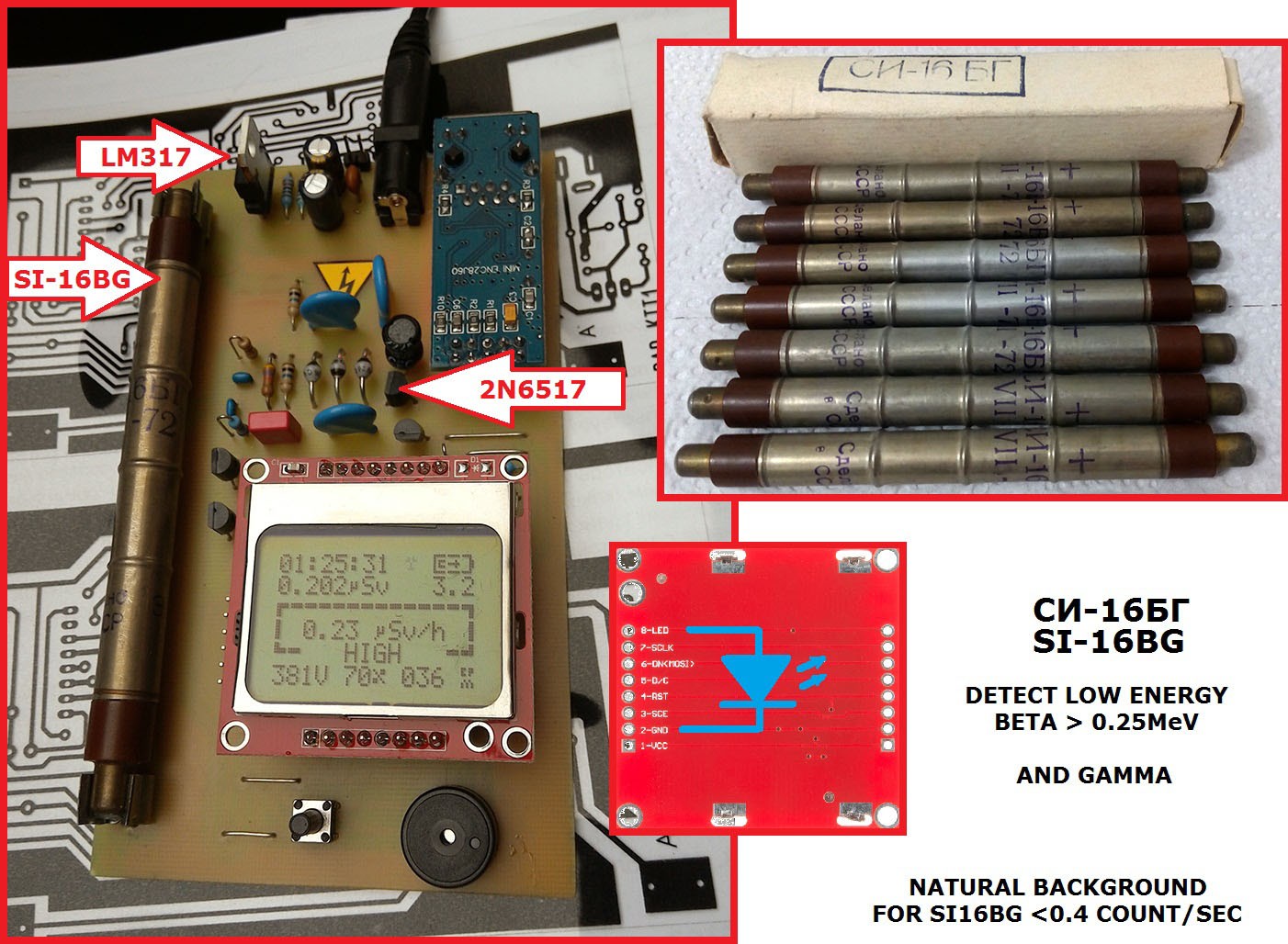
The server infrastructure
uRADMonitor is Big Data. Hundreds of detectors worldwide are collecting measurements every minute, and the server deals with millions of entries in its database every day. The database holding KIT1 data was designed for efficiency: only the minimum data goes in. One reason for open sourcing was to allow customising the KIT1 units with additional sensors. We had to adapt the server backend in this regards, and now there’s an expandable list of parameters that can be uploaded.
Then there’s the data accuracy which needs to be guaranteed to a reasonable degree by supervising and testing the hardware, something impossible with open, remote constructions. Making the server decide if the data is genuine or just some random useless bits was not an easy task.
Last but not least, here comes the security. Initially, open source can be a source of vulnerabilities of the exposed system. We had to make sure the new open communication protocol is safe to use. We’ve implemented API Authorisation...
 Mission accomplished.

 Here's Horia and Fabio, good friends from the
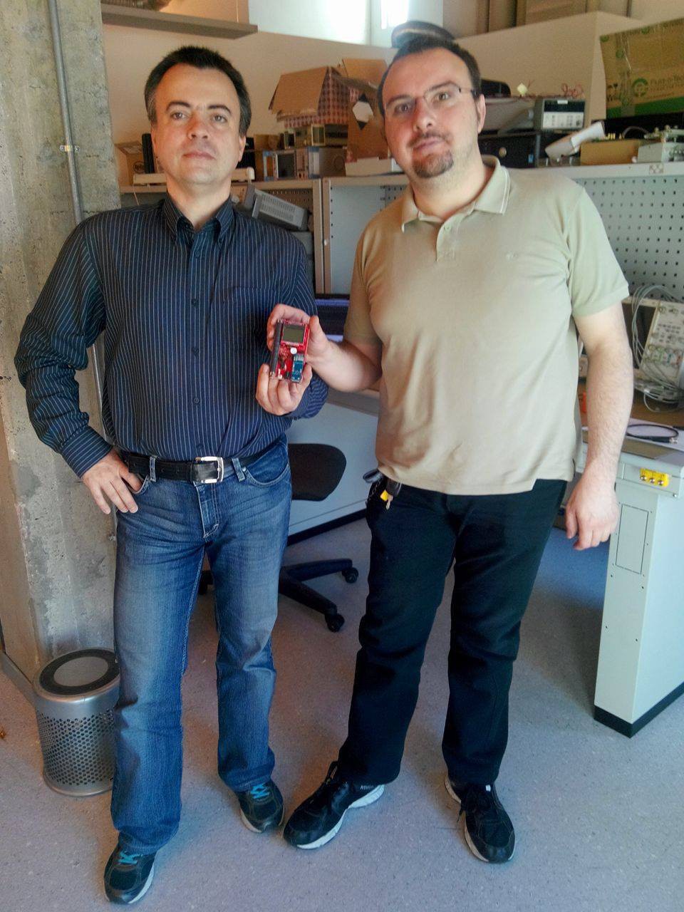


 And the masterpiece created by Akos, that you saw in one of the
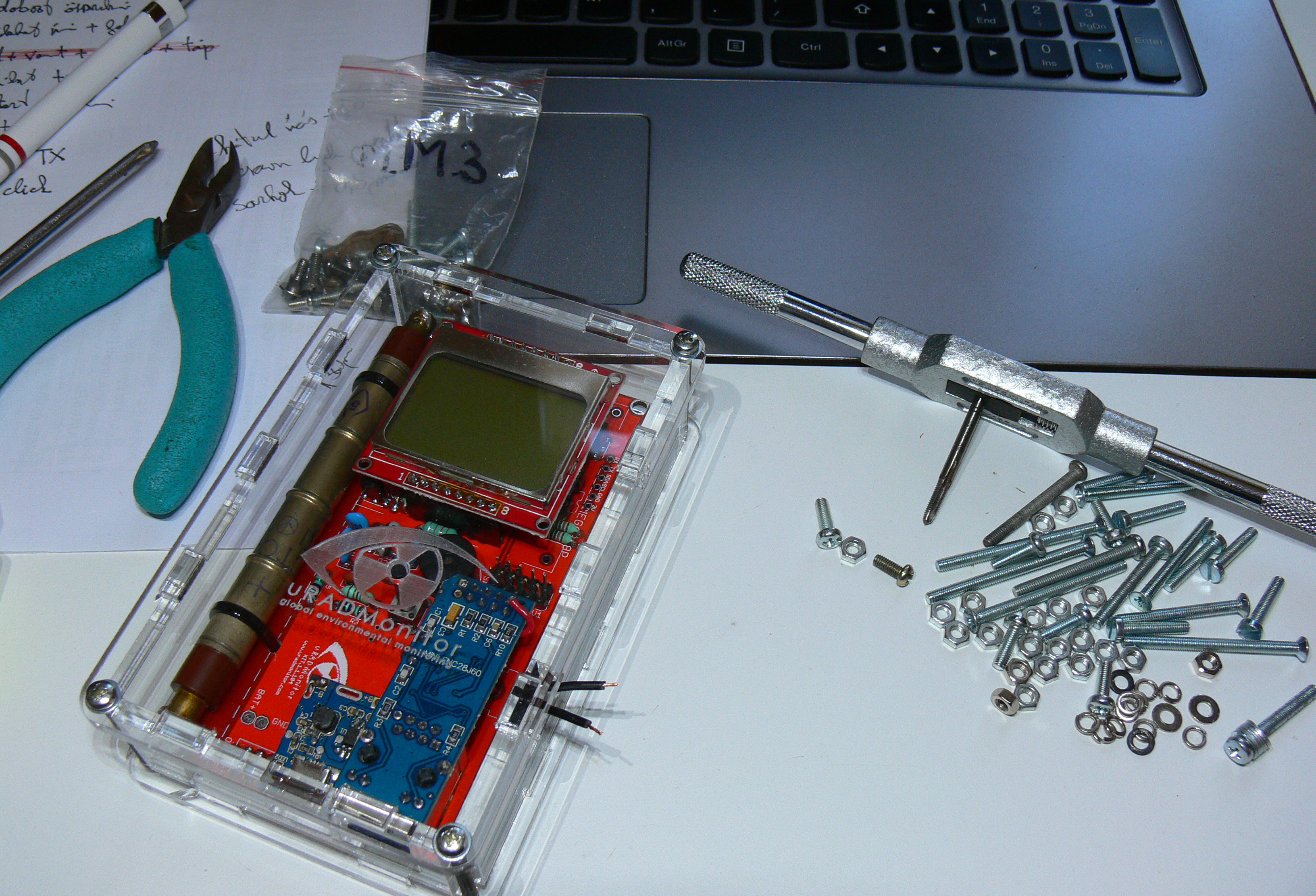
 You'll find the complete code there as well, or you can use this


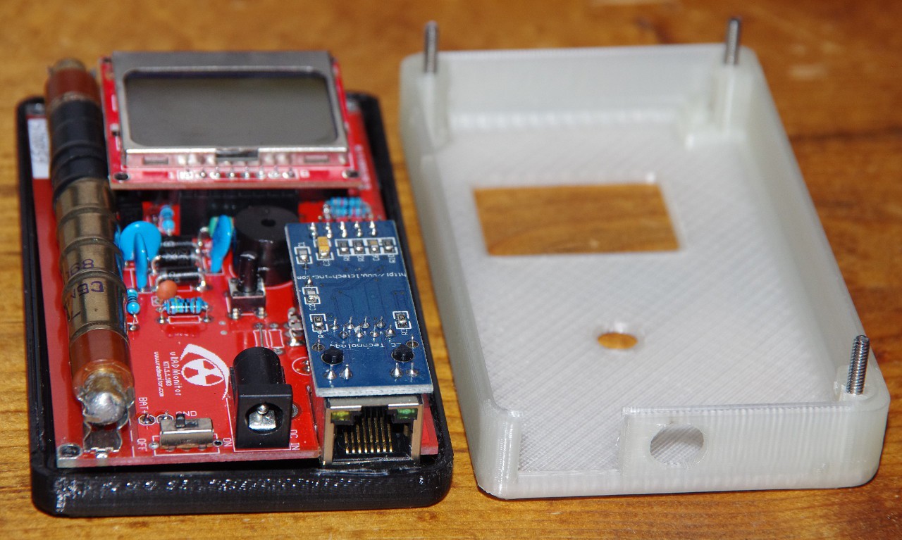
 To keep a safe distance between the aluminum foil of the battery and the bottom of the pcb (high voltage!), I used 4 self adhesive rubber shoes, like those intended for furniture.
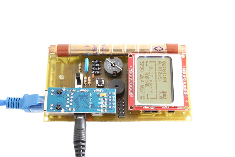 KIT1.1:
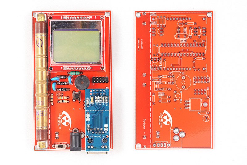


 Laurent
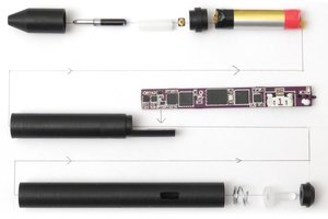
 Nick Ames
 Open Green Energy
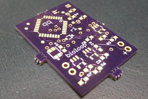
 qquuiinn
Fantastic work ) I'd like to make it on the base of my ESPboy. I think to start buyng SBM-20 Geiger tube )