• Version 3 Range of Motion Test

    Ben Nortier06/08/2018 at 09:47 0 comments

    I've assembled version 3! There are a couple of bugs :/. And room for many improvements. But it's useable for testing some of the control hardware & software.

    The servos are driven by an Adafruit I2C PWM driver (PCA9685) connected to a Raspberry PI over I2C.

    Here a simple range of motion test of all the servos:


  • Version 3 is ready for lasercutting

    Ben Nortier04/25/2018 at 08:45 0 comments

    I've worked on the shoulder/torso assembly and made some refinements to the legs and shoulder. I've replaced the 4mm smooth shaft that had to be cut with M4 socket screws and lock nuts. This requires a bit less effort and is cheaper. 

    The shoulder joint is M6 threaded rod that will have to be cut with a hacksaw. The shoulder to hip rods are M8 threaded and will also have to be cut from 1m stock.

    The mechanical parts (rods, screws, lock nuts) have been ordered from RS.

    I'm getting the 3mm plexiglass today and having it laser cut:

    Except I just realised forgot something :/

    Next update will be when I've assembled this version...

  • Autodesk Fusion to Mujoco simulation progress

    Ben Nortier04/10/2018 at 08:55 0 comments

    I've made some progress in writing code for converting from the Autodesk Fusion design to Mujoco for physics simulation.

    Here's the Fusion design:

    and the Mujoco simulation:

    The Fusion design has to follow some restrictions and naming convention for conversion, but I'm confident I can proceed to a more complex leg design, then a simulation of all 4 legs using OpenAI reinforcement learning.

    This implies that I will be able to modify the design in a high-level tool like Fusion and automatically do the reinforcement learning for walking. Because Fusion is parametric, it also implies I can write code to vary the design within certain parameter ranges (e.g. leg upper and lower leg lengths), and optimise the design using the simulation output.

  • Leg V2 super simple gait programmed

    Ben Nortier03/28/2018 at 15:13 0 comments

    I programmed a basic 4-phase gait:

    #include <Arduino.h>
    #include <Servo.h>
    
    Servo upper;
    Servo lower;
    
    int upperfrom = 25;
    int upperto = 125;
    int lowerfrom = 55;
    int lowerto = 125;
    void setup() {
      upper.attach(9);
      lower.attach(10);
      upper.write(90);
      lower.write(90);
      delay(1000);
      upper.write(upperfrom);
      lower.write(lowerfrom);
      delay(1000);
    }
    
    int phase = 0;
    int tick_counter = 0;
    int ticks_per_phase[] = {100, 50, 50, 50}; // Fast
    // int ticks_per_phase[] = {50, 20, 20, 20}; // Slow
    int upper_from_per_phase[] = {25, 75, 125, 75};
    int lower_from_per_phase[] = {80, 55, 125, 125};
    void loop() {
      int upper_from = upper_from_per_phase[phase];
      int upper_to = upper_from_per_phase[(phase + 1) % 4];
      int upper_pos = (upper_to - upper_from) * tick_counter / ticks_per_phase[phase] + upper_from;
    
      int lower_from = lower_from_per_phase[phase];
      int lower_to = lower_from_per_phase[(phase + 1) % 4];
      int lower_pos = (lower_to - lower_from) * tick_counter / ticks_per_phase[phase] + lower_from;
    
      upper.write(upper_pos);
      lower.write(lower_pos);
    
      tick_counter += 1;
      if (tick_counter == ticks_per_phase[phase]) {
        phase = (phase + 1) % 4;
        tick_counter = 0;
      }
      delay(10);
    }

    You'll have to turn your head upside-down...


  • Leg V2 with actuation

    Ben Nortier03/28/2018 at 12:39 0 comments


  • Leg Version 2

    Ben Nortier03/27/2018 at 16:02 0 comments

    After the last update I put some effort into the linkages. I bought a bunch of different hobby ones to see how they might work:

    The one on the right, where you can make your own length link seemed ideal.

    But I realised there's a problem. Version 1 had both servos in the "shoulder", but that severely limited the range of motion of the lower leg. I designed it like this initially to reduce the mass of the leg. It might still work but I need to carefully do a simulation to ensure proper range of motion.

    So I moved the 2nd servo to the top leg in Fusion. I also added links with ball joint, and experimented with the "Motion Study" feature. 

    Sadly this seems to be pretty buggy... :/

    With the new servo position, I updated the laser cutting drawings and got the parts back today. 

    Assembled. Eyeballed how long the top link should be:

    Repeated for bottom link.

    Now it's assembled and ready for Arduino:

    Close-ups:

    Looks decent. Hopefully I can now hook up an Arduino and experiment with controlling the leg. Easter weekend project...

  • Building the leg version 1

    Ben Nortier03/09/2018 at 11:12 0 comments

    TL;DR - I built the first version of a leg:

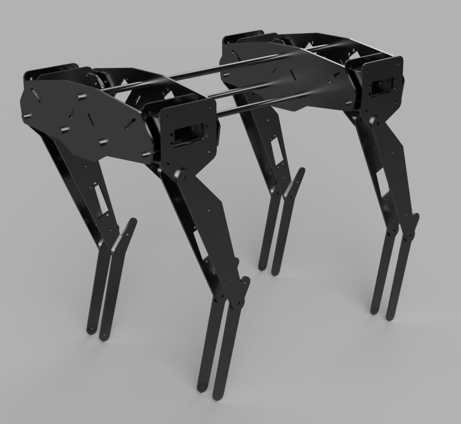
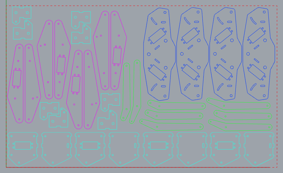
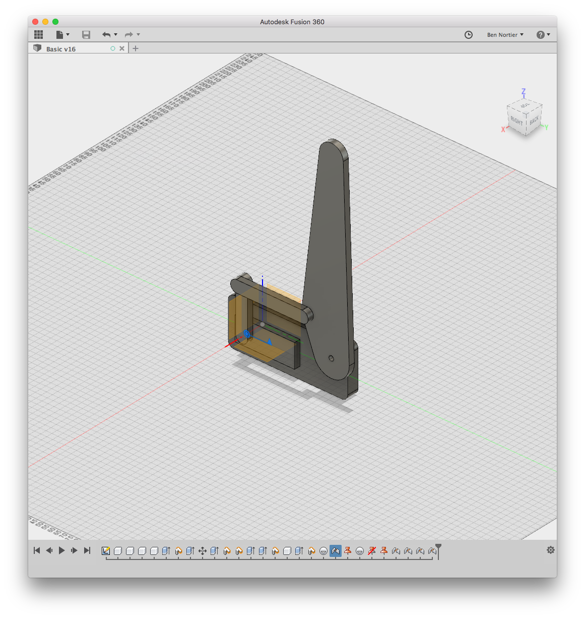
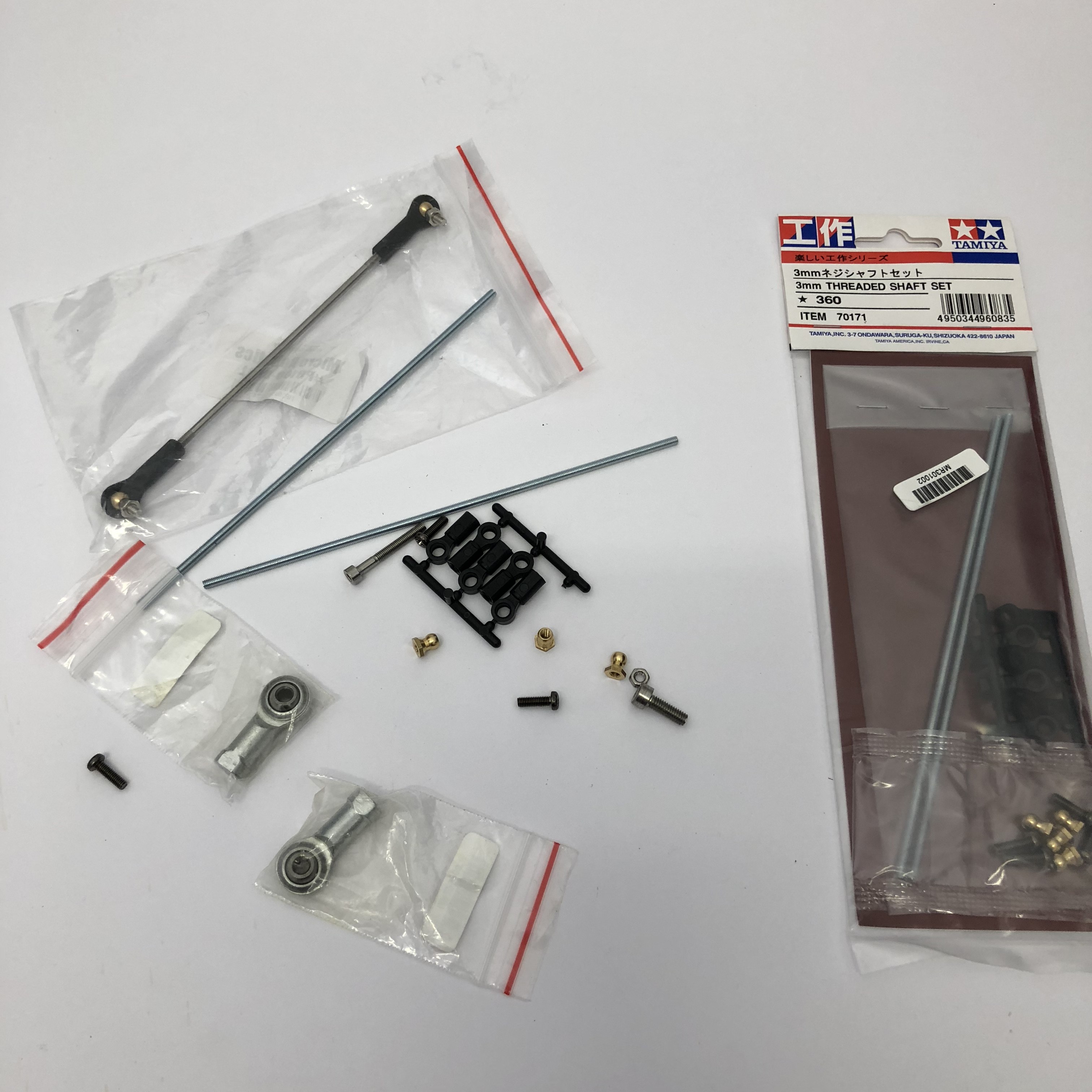
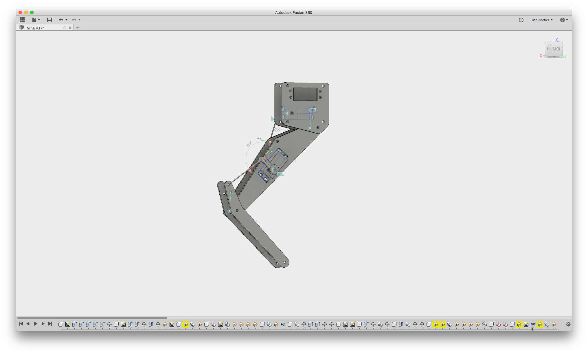
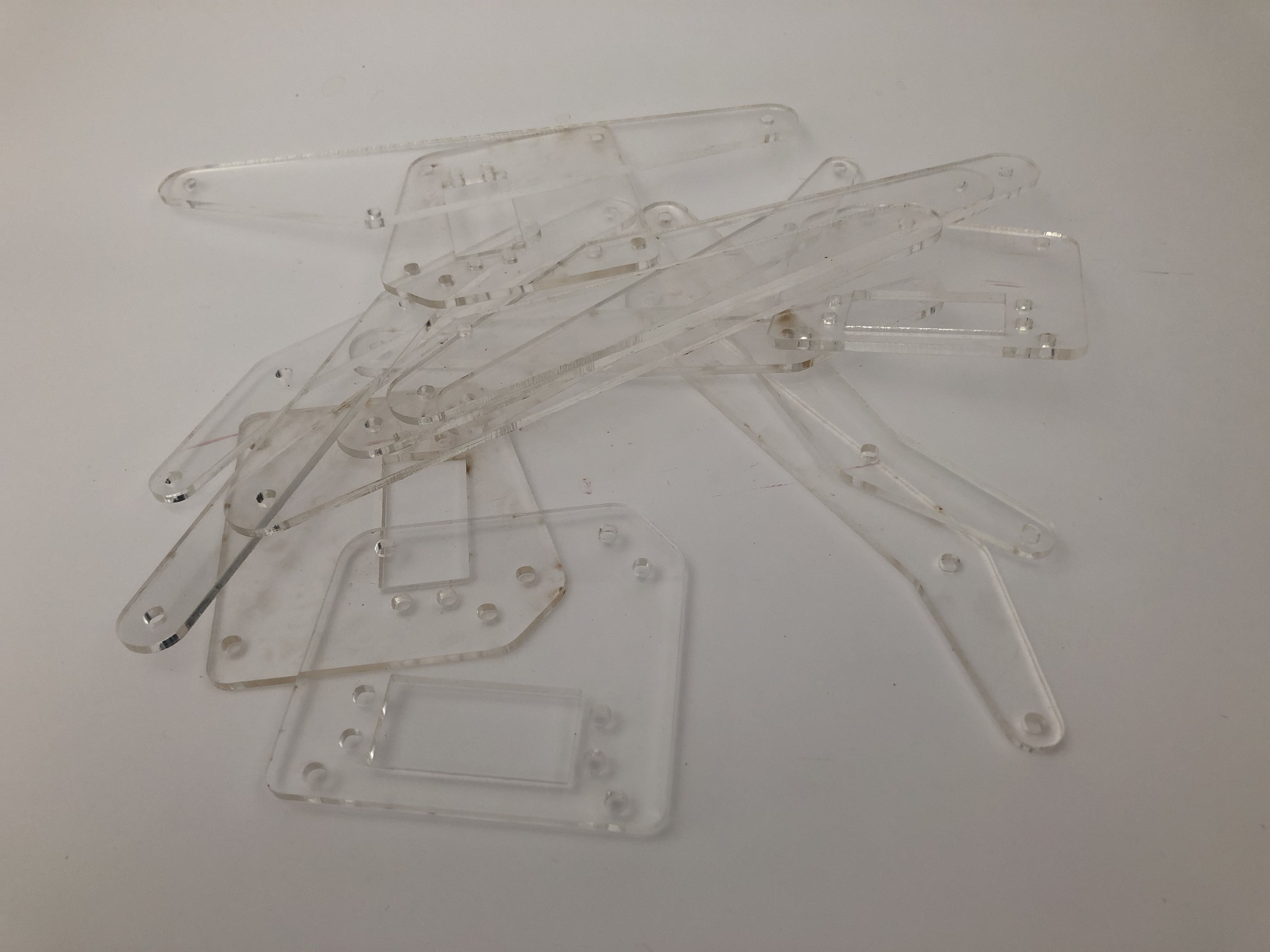
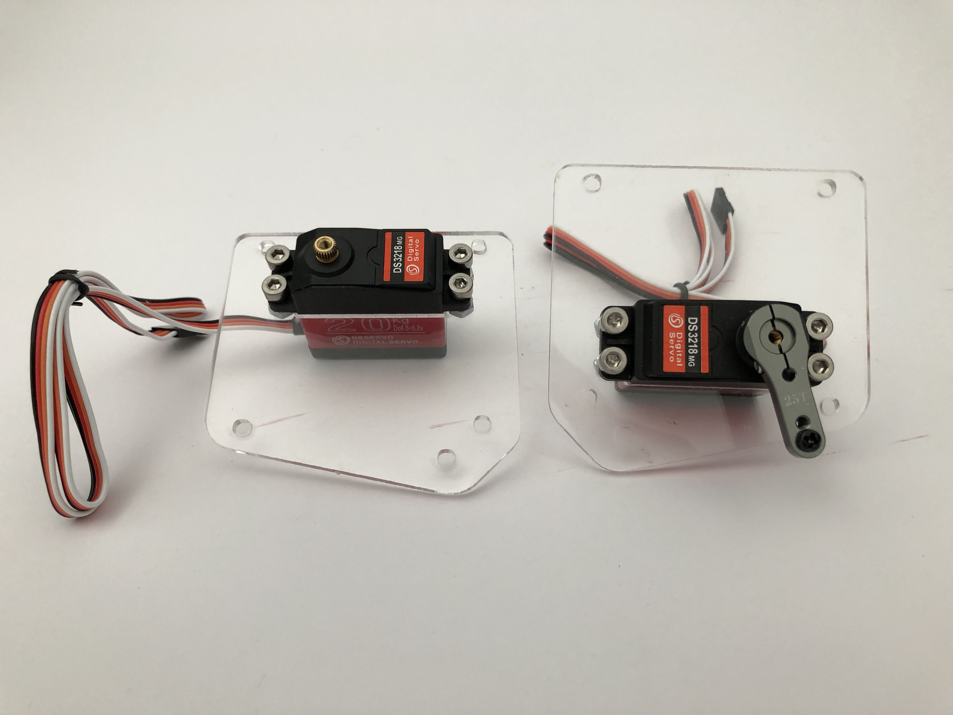
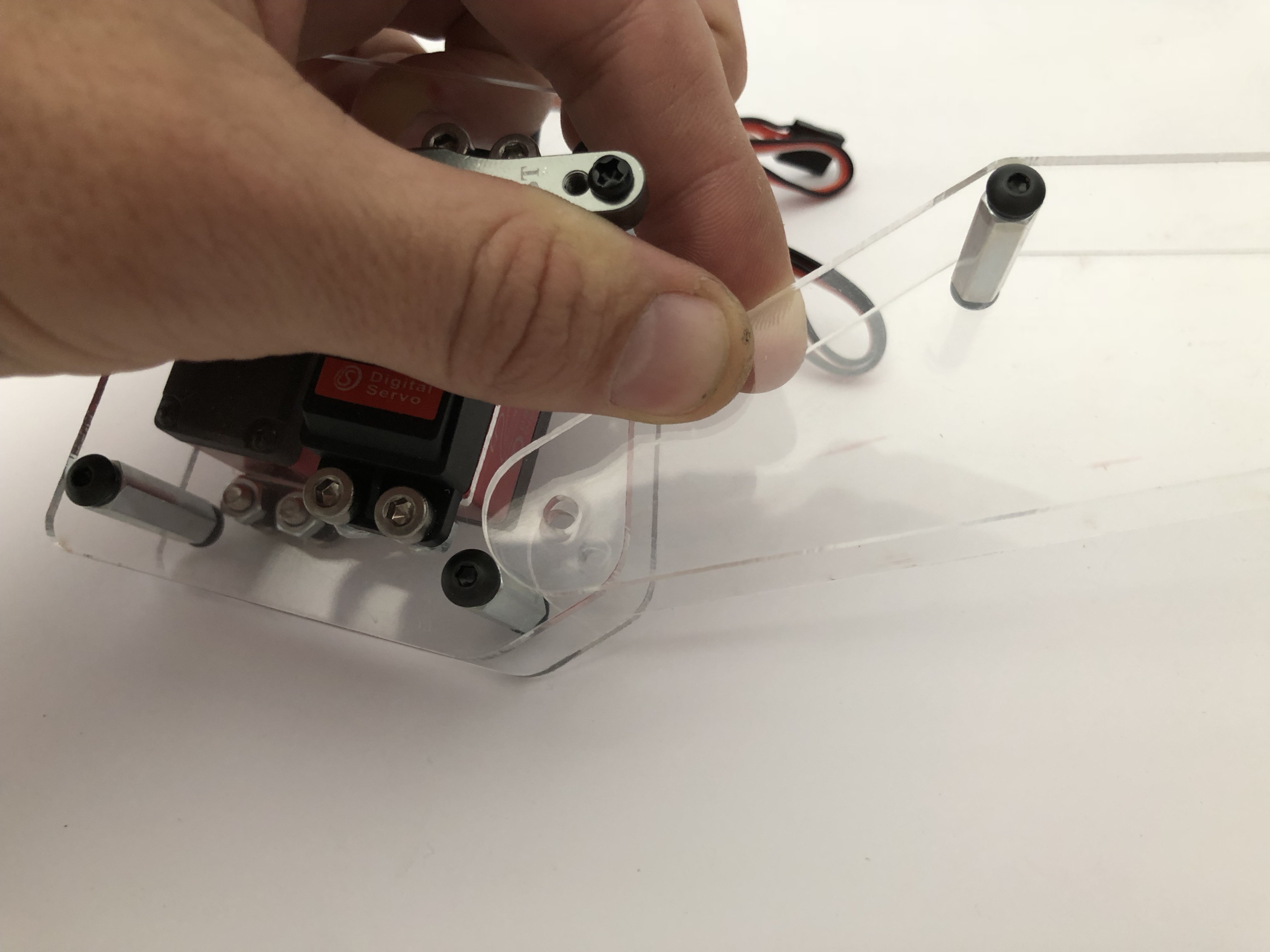
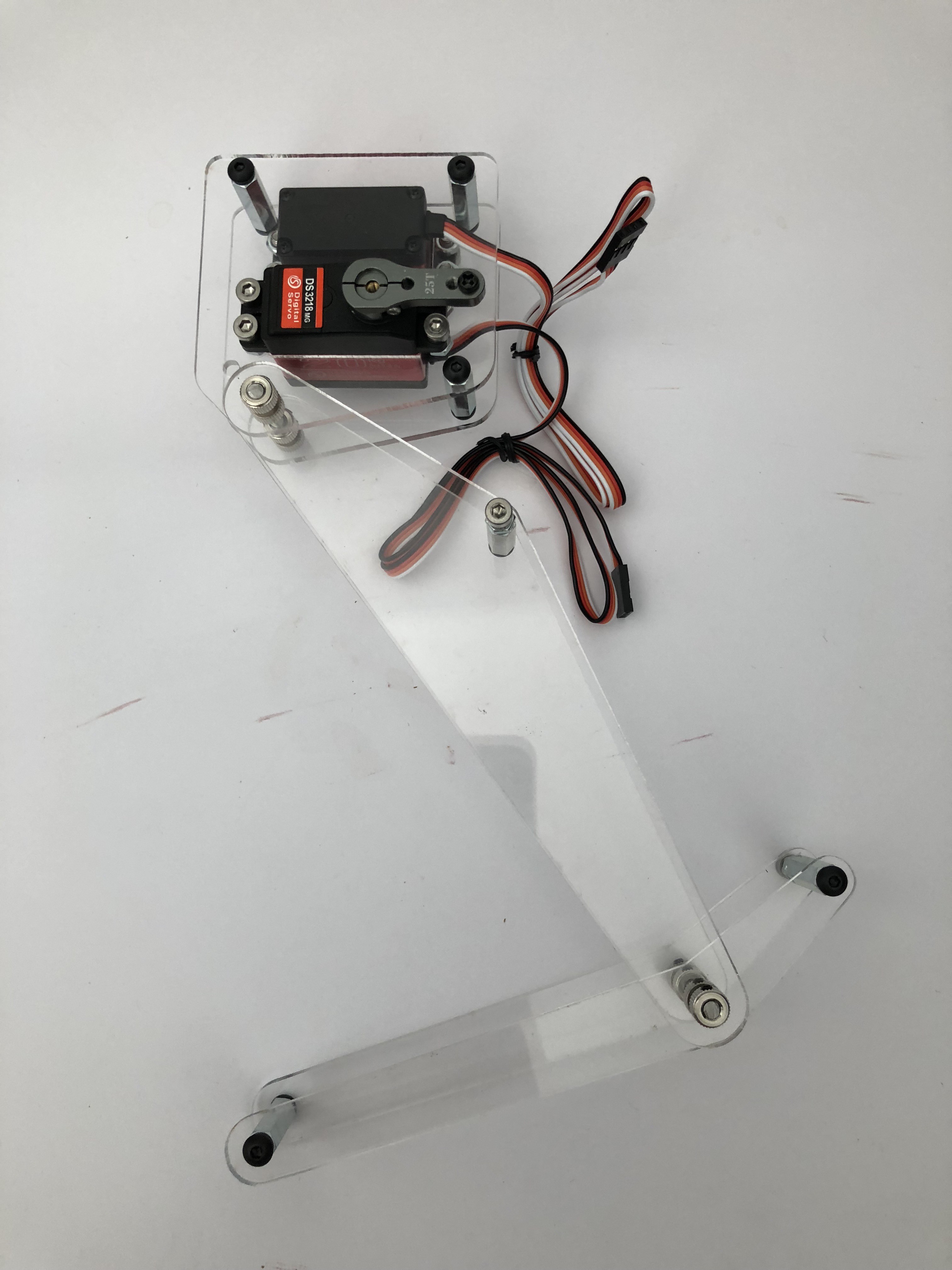
    I have some goals for the the mechanical design of this open source robot - it doesn't help if you make an open source robot but it requires a $ 500 000 mold! These goals are:
    1. Use readily available manufacturing methods (3D printing, lasercutting, CNC routing)
    2. Use off the shelf components (servos, Arduino, Raspberry Pi)
    3. Use readily available materials (carbon fibre sheeting, 3d printed plastics)

    I do want to make this into a kit, but anyone should be able to gather the components and make one themselves with the help of a makerspace.

    I've been using Autodesk Fusion for the first time to design this robot, it's taken a bit of getting used to but I do like the parametric design capabilities (I'm used to using Rhino). Version one of the robot looks something like this:

    1. It has 4 legs
    2. Each leg has 2 segments, with a servo and link each
    3. The shoulder can rotate 

    So we have 3 degrees of freedom for each leg, 12 in total. Servos are relatively cheap compared to torque motors ($15 vs $3000) so I'm going with servos for now.

    Some people who have built similar projects actuate the legs with the servo directly. I'm not convinced by this. I'm also not convinced that using a linkage is the right approach. Each has its advantages and disadvantages. In essence though, I don't like putting the servo under strain perpendicular to the servo axis, so in this design the leg segments have their own joints based on a metal shaft (more on this later).

    I had the prototype parts lasercut from acrylic (NB the thinking at the moment is to use CNC routed 3mm carbon fibre sheets, NOT 3mm acrylic sheets, but I have some acrylic handy and it's cheap so I'm using that for now)

    First set of parts:

    And the first problem:

    I didn't take into account the insertion angle of the servo :/

    Took out the file and started filing... and here's the two servos embedded:

    You can see I used 25mm standoffs. The nice thing here is the servos are 28mm from bottom to where they meet the acrylic, which is 3mm thick. So they fit snugly against the opposite layer:

    Slick!

    Then I hit my 2nd snag :/ 

    In the one corner, a 4mm Precision Round Bar with a hardness of HRC60-62.

    In the other corner, a small hacksaw.

    Hacksaw lost badly. It didn't even make a scratch!

    What to do.... I went to the hardware store to find a 4mm wooden dowel to use temporarily... but got a 5mm one instead. Fail. 

    Then I thought about something.... I have a little drill that also has tiny grinding discs. Which I've never used... Will it work? 

    Sparks! Here's to buying unnecessary tools. Got some safety glasses and set to work. 

    Shout-out to Zortrax who supplies a set of safety glasses with their M200 3D printer! That machine is fantastic. Highly recommended.

    The world tiniest angle grinder did the trick. 1 times 4mmx44mm shaft:

    I'm using 4mm shaft collars for the joint. Nothing fancy at this point. No bearing(s):

    3rd issue (3rd? I've lost count):

    The 4th standoff support is too close to the joint. I removed it. I don't actually think it's necessary since the shaft itself is fairly rigid.

    Femur attached:

    I have not idea how to create the link between the servo horn and the femur yet. Ball joint? It needs to be rigid... 

    Tibia:

    Front and right views:

    I'm pretty satisfied with this, considering it's the very first iteration. As soon as I've made a plan with the linkages I'll put an Arduino onto it for a bit of a demo.

    Please add questions and suggestions if you have any! 

    Woof.

  • Simulation Progress in OpenAI/Mujoco

    Ben Nortier03/08/2018 at 14:00 1 comment

    This is really an AI project, not a hardware project.

    What I'm trying to do, is to create an economical physical robot by utilising simulation as far as possible. Building a hardware prototype, then working on the control system, then iterating on the hardware, etc. etc. is a very laborious, expensive process.

    The good people at OpenAI (and others), are using simulated environments to train and develop robots orders of magnitude more cheaply (as far as labour is concerned). Using a simulated environment allows you to iterate very rapidly, and conduct experiments in faster than real-time. Here's an example of an OpenAI robot being developed: https://www.theverge.com/2017/5/16/15648158/openai-elon-musk-robotics-ai-one-shot-imitation-learning

    I want to build a robot dog, but my budget is very close to zero (relatively speaking, compared to a company like Boston Dynamics), and I'm interested in using machine learning to achieve this goal.

    i’m using OpenAI Gym as a starting point, together with Tensorflow and Mujoco. Mujoco is a physical simulation environment, designed for simulating robotics.

    Essentially, I need to create a simulated environment that is close enough to the real world physical properties of the mechanics, actuators and sensors of the robot so the controls mechanisms can be transplanted to a real robot.

    Lucky for me, there is a good starting point in OpenAI Gym — half a cheetah. I found the best listed solution in the OpenAI gym, written by a certain generous Mr. Pat Coady:

    https://learningai.io/projects/2017/07/28/ai-gym-workout.html

    Using his code and OpenAI Half Cheetah I trained this:

    Then improved the mechanical parameters and the reward:

    Added more legs:

    Created a body similar to the Netflix Black Mirror Metalhead bot:

    Improved the mechanical and reward parameters:

    More improvements:

    And now I have a reasonable model. Bridging the gap between the simulated model and an actual mechanical one is going to be tricky. It would require

    1. Accurately modelling the mechanical parts, including tolerances.
    2. Accurately modelling the joints.
    3. Accurately modelling the actuators.

    It's going to be quite a challenge.

    If you're interested in the code, all the code is on Github: https://github.com/bjnortier/max

    Sorry for the lack of details, please ask questions if you have any :)