Close
0%
0%

One Transistor Latch

Is it possible to make a latch with one transistor? Is it possible to use it to make logic?

Similar projects worth following
The third answer in the linked stack exchange post suggests that it might be possible to make a latch with one transistor .The idea is that logic values are represented by presence or absence of a specific frequency oscillation instead a high or low voltage.

Is this actually possible? If it is, can you build digital logic based on this technique. Can it be simpler than conventional transistor transistor logic?

This would be similar to "code golf" where you try to write the shortest program to do something.

Probably a quixotic search, but I think I'll learn a lot about transistor math in the process.

A separate project that is interesting to me is to make a microprocessor with a minimal number of transistors. Wikipedia says that an 8080 has about 4500 transistors. Can that be substantially decreased? If you take out some of the features like interrupts and BCD is it possible to use fewer (performance be damned).


Patent-US3811076.pdf

This is a patent from 1973 creating a memory chip from one transistor and one capacitor per bit.

Adobe Portable Document Format - 682.34 kB - 03/28/2018 at 20:16

Preview
Download

  • 1 × Transistor
  • 1 × capacitor

  • Parametron

    Bill Smith05/27/2020 at 20:41 0 comments

    I was researching early computer technology and found references to a circuit used by some Japanese systems called the Parametron https://en.wikipedia.org/wiki/Parametron It resembles some of my ideas for this circuit. I had been thinking that the circuit would represent 1 vs. 0 by the phase of an oscillating signal with 180 degrees apart would be the 1 and 0 values.

    One advantage of the parametron design was that it was more reliable than early transistors.

  • It was already done in 1973.....

    Bill Smith03/28/2018 at 20:15 0 comments

    Actually this project was already solved in 1973 by my dad!  Patent https://patents.google.com/patent/US3811076 is for a memory chip made from one bit latches containing one FET transistor and 1 capacitor/

  • ↓ one down

    Bill Smith12/07/2017 at 16:56 0 comments

    I checked the idea of using two capacitors. It doesn't work.

    It's hard to get a sample image from my simulation that is easy to explain, but it is not going to work.

  • waveform # 1

    Bill Smith12/07/2017 at 16:51 0 comments

    This is one possible waveform for voltage on the latch's main capacitor. The idea is that the high (red) and low (blue) values are 180° out of phase from each other.  The power signal provides the concept of phase.

    There has to be at least an additional capacitor or inductor to distinguish the state when the two waveforms cross each other.

    [I put this in description instead of project log. moving it here]

  • 180 degrees out of phase

    Bill Smith10/09/2015 at 16:32 0 comments

    While brainstorming, I thought of a potential implementation. The signals would oscillations 180 degrees out of phase to represent zero and one instead of yes oscillation/no oscillation.

    Another brainstorming idea is to make the power supply oscillate at twice the speed of the data's oscillation. Most probably the polarity of the supply wouldn't go from + to - . Instead it would be offset from zero by a volt or two. For example, Peak to peak might between 1V and 4V.

View all 5 project logs

Enjoy this project?

Share

Discussions

roelh wrote 03/29/2018 at 20:00 point

Hi Bill,

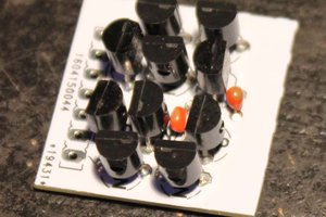
inspired by your project and the answer from Ted Yapo, I did build the following on a breadboard:

http://www.enscope.nl/rrca/ideas/single_npn_latch.png

This is a working design, but it will most likely need further improvement, especially when you want high speed.

How does it work ?

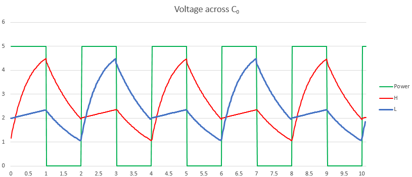
A 5 volt (TTL) clock is needed, that is in common for all latches, and present all the time. I used 3 kHz.

The output has two states:

1) in the OFF state, the 5V clock signal is strongly attenuated by the 6K8 resistor and the 3K3 - C2 combination. The signal on the base of the transistor is below 0.6 Volt, so the transistor stays off (output high, LED off).

2) The latch can be put in the ON state by shortly applying a 5V pulse to C2 via a series resistor. This will change the operating point of the transistor. The DC voltage on C2 will provide a bias voltage to the base, and the transistor will now amplify the clock signal. So, in the ON state, the output has the clock signal, the LED will be ON. The output signal will be rectified by the C1 - D1 combination, and the resulting DC voltage will appear on C2. This closes the positive feedback loop, and the latch will stay in the ON state. However, the DC on C2 could be so high that the transistor is ON all the time, and that would remove the positive feedback signal. To prevent this effect, D2 is added. Each time the output of the transistor is low, it will discharge C2. When the circuit is properly dimensioned, D2 could also act as a Baker clamp to prevent saturation of the transistor.

You can bring the latch back to the OFF state by discharging C2, or by shortly removing the clock signal.

If you want the latch to be fast, you should make C1 and C2 smaller, and use a clock that is a few times faster than the maximum operating speed of the latch.

  Are you sure? yes | no

Ted Yapo wrote 03/30/2018 at 00:52 point

Yes, I just simulated this in LTspice, and it works!  I used the initial condition at the node between C1 and D2 to set the  state of the latch at the beginning of simulation. If it's on, it stays on, and if it's off, it stays off.  Very nice!

  Are you sure? yes | no

roelh wrote 03/30/2018 at 19:42 point

Hi Bill, Ted,

I added my design in the 2018 competition. See https://hackaday.io/project/112126-one-transistor-flipflop

  Are you sure? yes | no

Ted Yapo wrote 12/07/2017 at 18:29 point

What about using both AC and DC supplies?  This is how #The Diode Clock works, for example - it uses an RF power supply with DC bias controlling PIN diodes (1N4007s).  Maybe you could make a one-transistor latch along the same lines as the old one-transistor reflex radios, where the same transistor amplified both RF and audio?

Maybe the transistor can switch RF that it also rectifies to produce its own bias, and work like the two-diode latch I added this morning? https://hackaday.io/project/11860-diodes-only/log/71315-two-diode-latch

  Are you sure? yes | no

Bill Smith wrote 12/07/2017 at 16:59 point

I'd like to only use one silicon component. Once I get an idea that simulates ok, I'll have to see how fast I can make it too....

  Are you sure? yes | no

agp.cooper wrote 12/31/2016 at 08:19 point

Hi Bill,

Two transistors, most definitely.

One transistor? Yes but messy!

I came across something a worth a look a few day ago.

It was a neon latch or memory circuit.

This was not it but similar, see ge69.jpg in http://www.tuberadios.com/ge.zip.

Found it: http://hackaday.com/2016/12/12/the-many-uses-of-the-neon-lamp/.

So swap the Neon with a transistor in reverse CE breakdown mode (about 8v) as shown in this relaxation oscillator:


You will find similar circuits using tunnel diodes.

Regards AlanX

  Are you sure? yes | no

Bill Smith wrote 01/02/2017 at 00:20 point

Thanks for the info! 

  Are you sure? yes | no

matseng wrote 01/02/2017 at 01:06 point

That is kinda strange, I also just recently stumbled across an old article about a neon-based latch/memory design.

I guess that it might have been a link from inside the pages from one of Yann's postings.

A few kilobytes of neon memory would look awesome, I really would like to see one....

  Are you sure? yes | no

matseng wrote 01/02/2017 at 01:08 point

hmmm...  Saw the "Found" note one your post. :-)   So not posted by Yann then... But it easily could have been - it's straight up his alley.

  Are you sure? yes | no

Similar Projects

Does this project spark your interest?

Become a member to follow this project and never miss any updates