 Dave Vandenbout
Today I selected one of the best boards for the initial prototype. I probed it with a continuity tester to make sure the voltage planes (5V, 3.3V, 1.2V, VCCIO3 and GND) were not shorted and that each plane was connected to the correct pins of the iCE40's BGA package. I also checked the BGA pins surrounding each power supply pin to see if any of them were shorted to power or ground.
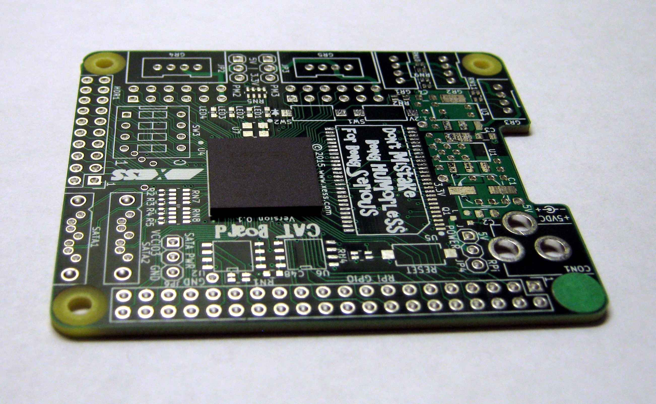
After verifying there were no shorts or opens on the power planes, I mounted the BGA onto the CAT PCB using the method illustrated below.
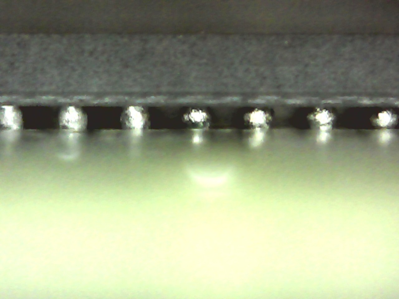
Afterwards, I used a $50 USB microscope to examine the BGA solder balls. The solder balls haven't collapsed uniformly, but it's good enough for the prototype. Shining a bright light from one side of the BGA while looking into the opposite side also showed the absence of any shorts between adjacent columns or rows. Of course, there's still the problem of opens in the interior but I can't check for those without an X-ray machine.
Discussions
Become a Hackaday.io Member
Create an account to leave a comment. Already have an account? Log In.
Hi, Yann. Thanks!
Are you sure? yes | no
Nice work !
And I just realised that you work(ed) for XESS :-) Glad to see you here !
Are you sure? yes | no