Close
0%
0%

Alternate Firmware for FG-100 DDS Function Gen

Reverse engineer the FG-100 pinout and develop alternate firmware that improves some of the shortcomings of the default firmware.

Similar projects worth following
The FG-100 is a cheap function generator available off Ebay. Is a Chinese made unit of fairly good build quality (includes rubycon caps etc). While the unit provides a stable output waveform it lacks the ability to adjust the frequency while generating a wave (have to stop and start the output), and the UI has a few annoying quirks. This projects initial goal is to create replacement firmware for the unit that improves the UI and then to look at any other improvements that can be made.

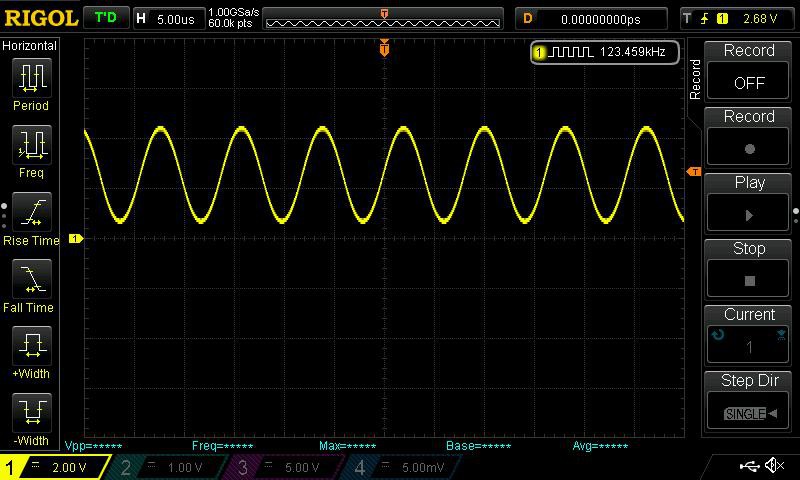
Unit is powered by an ATMega48 (socketed 28pin DIP), waveforms are generated using an 8Bit R2R ladder off of PORTD. As the micro is socketed I will be developing the alternate firmware using a pin compatible ATMega328P.

At this point the pin out of the micro has been established as well us how each of the buttons and other components are being used. And a firmware clone has been developed that provides the existing feature set, the project has now moved onto enhancing the original feature set. Initial new software features:

  • Frequency sweep between two defined frequencies within a defined period.

And following from that some hardware features:

  • Adding a rotary encoder

sh100-1.0.hex

1.0 Release

hex - 17.17 kB - 04/23/2017 at 16:35

Download

fg100alt-0.2.hex

Hex file for the 0.2 release

x-hex - 15.01 kB - 03/08/2016 at 02:42

Download

  • 1 × FG-100 Function Generator Search on Ebay or your favourite outlet Shenzen outlet.
  • 1 × ATMega328P Microprocessors, Microcontrollers, DSPs / ARM, RISC-Based Microcontrollers

  • Release 1.0

    Tim Savage04/23/2017 at 16:37 0 comments

    Just released version 1.0 of the alternative firmware. The internal name has been changed to SH-100 to indicate big contribution from crHARPER.

    Full source etc on GitHub (any bug reports there please).

    Enjoy.

  • A big contribution and a 1.0 release.

    Tim Savage04/19/2017 at 00:11 0 comments

    A huge thank you to chHARPER for contributing a whole array of improvements/bug fixes to the firmware.

    • Improved button operation.
    • Easier frequency setting with digit rollover, or wrap-around (9 to 0 and 0 to 9).
    • Settings saved to EEPROM when Run Button is pressed.
    • When Cursor Button is held down (>5 sec.), frequency resets to zero to simplify setup.
    • Full 500KHz operation now implemented.

    I received a pull request from him this morning and will be testing the changes over the next few days, if all goes well a 1.0 release with the changes soon after.

    Open source/development wins again!

  • The next step

    Tim Savage02/14/2017 at 14:43 0 comments

    At the end of the road for this project, I've moved on and started the Funktion Generator project, this project that will utilise multiple microcontrollers with one doing DDS synthesis and anothiner driving the UI, this allows for adjustments on the fly etc. Good progress has already been made, with the power supply (with +-9V rails) built and working, and the firmware for the DDS generator running and accepting commands vi I2C/TWI.

    See: https://hackaday.io/project/19866-funktion-generator

  • GIT swap around and second release

    Tim Savage12/11/2015 at 13:09 0 comments

    Picked up a few great tips from today's Embed with Elliot (Debounce your noisy buttons, part II) and the buttons are now all nicely de-bounced. However I was a little premature moving onto the major improvements. This required some GIT voodoo the outcome of which all major improvements are now on the ng-dev branch and master is back to being the stable released branch.

    So with the changes out of the way tags have been pushed for release 0.2 which fixes the bouncing issues with buttons. There is still one outstanding issue relating to the start/stop button, it's not possible to really de-bounce this button once DDS generate has started so I've simply added a 1/4 second delay to give the user time to release the button.

    The next generation of the firmware does present some issues and I'm considering starting a new project entirely to build a DDS generator from scratch but utilising two micros, one for DDS generation and one for the UI. This would allow for much nicer UI interaction and to make on the fly changes to frequency. I believe sweep functionality can be easily added to this solution however which would greatly improve the usefulness of this product, that however will be the last improvement I will make.

  • Demo of first Release

    Tim Savage12/07/2015 at 12:12 0 comments


  • Frequency Sweep

    Tim Savage10/30/2015 at 16:36 0 comments

    Proof of concept was successful and I can get generate a frequency sweep using a timer to increment the size of the frequency step, effectively adjusting the frequency. Next steps are to add UI to specifiy a start/dest frequency and a sweep period.

  • First release

    Tim Savage10/28/2015 at 14:41 0 comments

    After a tweak to the approach used to break DDS loop, I have a version that I consider to be 0.1 video to come soon.

    Release has been tagged in Git. See GitHub project page for build/install instructions. I would suggest installing the tagged release (release-0.1) or install master if you want to try out the latest changes (nothing really as of writing this summary).

    Time for new features! :)

  • UI

    Tim Savage10/25/2015 at 15:45 3 comments

    UI to select wave form and set frequency working (and the first of the improvements, cursor will remain at last location).

    Next steps are to modify the DDS loop to be able to break out and implementation of the run/stop button via an interrupt.

    With that the initial goal of an equivalent firmware with some of the UI quirks fixed is reached. Following from that the next steps are:

    • Improved input context, allow the mode button to select the input context, initially frequency and function but that then provides for the ability to configure a sweep.
    • Support for sweeping frequencies, likely implemented with a timer interrupt to adjust frequency.
    • Adding support for interaction via a rotary encoder,, to use some of the free pins, if implemented with interrupts this could allow for configuration of the frequency while it's running.

    There are certain hardware limitations (eg buttons require row scanning) that does make certain things difficult while trying to run a tight loop required to do DDS. The next project will likely utilise 2 micros, one running DDS that is slaved to a master for implementing UI.

  • LCD Driver complete

    Tim Savage10/23/2015 at 15:30 0 comments

    LCD driver code added, based on https://github.com/aostanin/avr-hd44780 with modifications to work with the reversed PIN used.

    A basic UI has been put together. Latest code pushed back to Github.

    Next step is to get button row scanning and interrupts working. ASM for the DDS loop needs to be breakable so changes can be made.

  • Frequency control

    Tim Savage10/20/2015 at 14:15 0 comments

    Just got frequency control code to work. Is based on the work of Joonas Pihlajamaa in this article which in tern is based Jesper Hansen's work. However I have made some changes to the control loop to use a 24bit step while still using SRAM. This provides much more accuracy at low frequencies, the 16bit implementation spikes up to around +-18% error vs 24bit which reduces this to a peak of +-0.013%*

    * See this spreedsheet for the modelling I used to come up with the error values.

    Set to 123456Hz ;)

    Latest code has been pushed toGitHub. Onto UI...

View all 14 project logs

Enjoy this project?

Share

Discussions

Aaron wrote 07/09/2023 at 03:58 point

Just ordered off Amazon, it had a ATMEGA48V-10PU.

  Are you sure? yes | no

al-davis wrote 06/03/2022 at 19:11 point

Anyone have a FG100 with a DIP CPU they'll sell me so I can continue this project, message me.

  Are you sure? yes | no

al-davis wrote 06/02/2022 at 22:45 point

Well the hardware arrived but the bad news is the CPU is no longer on a socket AND it is a surface mount part.   Device looks the same on the outside but not on the inside.  The LCD is a 1602.  CPU is a MassDuino MD-3248p, so far can't find a pinout on this 48 pin chip.  FWIW the device has good looking and accurate waveforms, but I don't even need a function generator.  I only bought it as an exercise in hacking.

  Are you sure? yes | no

Tim Savage wrote 07/17/2022 at 23:49 point

That does make things hard, the original micro was firmware locked hence I had a swap out the micro along with the firmware.

  Are you sure? yes | no

al-davis wrote 05/30/2022 at 17:56 point

Current status on the Windows version is ONLY that it compiles.  I am waiting on hardware to continue with the project.  It would be premature to put in on GitHub, may have been premature to even post about it.

  Are you sure? yes | no

Tim Savage wrote 07/17/2022 at 23:56 point

The existing code should compile on windows. There is nothing Linux specific here, requires an AVR compiler (avr-gcc) and make. There is Python util for generating waveform tables but that was only included for completeness.

  Are you sure? yes | no

al-davis wrote 05/30/2022 at 01:14 point

I know this project is very old.  I have ported the GitHub SW (Linux) to a Windows environment ( Adruino IDE).  Message me for a copy.

  Are you sure? yes | no

Tim Savage wrote 05/30/2022 at 05:01 point

Could you open a PR on GitHub and merge the required changes there?

  Are you sure? yes | no

dave11674 wrote 05/30/2022 at 08:34 point

could i get a copy pls ?

Any chance you could modify it so it boots up to 60hz sine pls ?

Thanks

dave11674@gmail.com

  Are you sure? yes | no

dave11674 wrote 09/11/2020 at 11:51 point

Hi guys, i was wondering if in this firmware we could set it to come on and run @ 60hz sine ? as we have one of these in one of our imported pinball machines and each day we need to set the frequency before the game boots its program or it crashes. thanks

  Are you sure? yes | no

Tim Savage wrote 05/30/2022 at 05:03 point

The source code could be modified to do this yes.

Most of the code is to implement the UI, the actual DDS section is a small block of ASM. 

  Are you sure? yes | no

dave11674 wrote 05/30/2022 at 08:35 point

thanks, where would i need to look in the source for the ASM block please

Thanks


dave

  Are you sure? yes | no

Tim Savage wrote 05/30/2022 at 08:59 point

The DDS code is all encapsulated in the dds.* files in the src folder. 

By default the last frequency used is saved in the eeprom which would let you set the frequency you want to use, getting it to start outputting at startup would require adding `DDS_ENABLE` to line 100 of `main.c`.

That will cause the state machine to start the DDS output.

  Are you sure? yes | no

dave11674 wrote 05/30/2022 at 09:08 point

excellent

Ill have a peek n poke Wednesday when i get into work.

Thank you very much :)


now i need to figure how to program my atmel chip

Ive many programmers.

Hopefully one supports this chip


dave

  Are you sure? yes | no

dave11674 wrote 05/30/2022 at 09:26 point

ok

so i added

but it does not look right in the code

//-----------------------------------------------------------------------------
int main(void) {
    init();
    
    config_init();  //get saves setting from EEPROM
    
    _delay_ms(2000);
    ui_redraw_display();
`DDS_ENABLE`
    while (1) {
        operator_input();

        if (DDS_IS_ENABLED) {
            lcd_disable_cursor();
        
            dds_start(ui_state.frequency);
        
            lcd_enable_cursor();
            DDS_DISABLE;
        }
        
        // implement sleep mode here to save power
        _delay_ms(100);
    }
}

look right to you

thanks

dave


  Are you sure? yes | no

dave11674 wrote 05/30/2022 at 09:33 point

so i dont need to set it to 60 in the dds files

if it remembers its last setting this is good enough for me at poer up :)

the machine can be powered down for 4-5 days in some cases, hopefully it will still remember ?

oh but on a side note, if im putting the DDS_ENABLE into main.c will it not auto start the default frequency on first bootup ?

i can alway stop it and then set 60 correct ?

sorry for all the questions, this FG-100 is new to me :)

thanks

dave

  Are you sure? yes | no

tonys0 wrote 08/02/2018 at 03:31 point

I have been able to load the release 1.0 hex-file with Xloader  to an ATMEL328P chip on Arduino Uno and it actually works in the FG-100. One has to press and hold the buttons a while to make them work. 

I also tried to split the main() in setup() and loop() to use the rest of the software as an Arduino project, but that did not work so well. After some small tweeking with #include files I could actually compile the whole sketch, but already handling the LCD display has some issues. Probably some differences in treating the EEPROM and cursor handling. I could not figure out, what was the BUTTON_STROBE.

I think moving the project to Arduino platform would boost the development a lot, since many more people would feel involved. Of course, that would also invite to rewrite the parts of code where convenient, like

    // Configure Strobe as Input
    DDRB  &= ~_BV(BUTTON_STROBE);
    PORTB |=  _BV(BUTTON_STROBE);   // Enable pull up resistor
    // Configure Run/Stop as Input
    DDRC  &= ~_BV(PINC3);
    PORTC |=  _BV(PINC3);           // Enable pull up resistor

to something more readable, like

pinMode(BUTTON_STROBE, INPUT_PULLUP);

pinMode(PINC3, INPUT_PULLUP);

when there is actually no rush in performing INPUT/OUTPUT handling.

Let me know if somebody is interested in moving this project to Arduino.

  Are you sure? yes | no

Tim Savage wrote 05/30/2022 at 05:14 point

By default the Arduino framework expects a 16Mhz clock, this greatly limits the range of frequencies that can be generated. The unit I have has a 30Mhz crystal and this is what is the default that it's compiled with.

Also, be sure to disable interrupts in Arduino as they will interfere with the timing of the DDS generation loop, a stable waveform requires precise known timings/number of clock cycles.

  Are you sure? yes | no

Tim Savage wrote 07/18/2022 at 00:03 point

When I origionally wrote this, I specifically chose not to use Arduino for both the reasons above and to get some experience writing a complete firmware.

The code above for configuring ports is quite readable if you are familiar with bit manipulation and the configuration of a microcontroller from a datasheet. 

  Are you sure? yes | no

Tim Savage wrote 03/08/2016 at 02:50 point

Project has been fairly quiet over the last few months. However I've started making progress again and have started designing my own generator (well the power supply at least). Will be based on much of the work used in this project. Having recently moved house (well city) I've finally got my workbench setup again. My evolution of this project will use a pair of micros, one for DDS generation and the other to control the UI. 

Anyway lots more to come! I may still look at adding sweep functionality to this firmware just need to evaluate the impacts on the output of the DDS.

Note I've added a copy of the HEX file generated by the build (make sure the correct fuses are also set when uploading).

  Are you sure? yes | no

Jarret Chessell wrote 10/18/2015 at 00:44 point

Someone already pointed to this project on my FG-100 youtube video, good job, keep it up! I was thinking about building my own ZIF socket dev boards for atmel and pic's in the near future.

  Are you sure? yes | no

Tim Savage wrote 10/20/2015 at 00:15 point

It's proving to be really handy especially swapping the IC into the actual unit to test.

  Are you sure? yes | no

Jarret Chessell wrote 10/09/2015 at 22:56 point

How did compatibility with the 328p go?

  Are you sure? yes | no

Tim Savage wrote 10/10/2015 at 01:17 point

That's up next, I've setup a rough approximation of the R2R ladder on a breadboard, once I have a decent waveform outputting on the scope from my development setup I'll drop it into the socket and test it.

  Are you sure? yes | no

Tim Savage wrote 10/10/2015 at 02:54 point

Just dropped the micro into the FG-100 and everything worked as expected. I've got a lot of work to do on the firmware now. 

  Are you sure? yes | no

Similar Projects

Does this project spark your interest?

Become a member to follow this project and never miss any updates