 David Reiss
(Scroll to the end for videos of the completed project working.)
Initial Construction
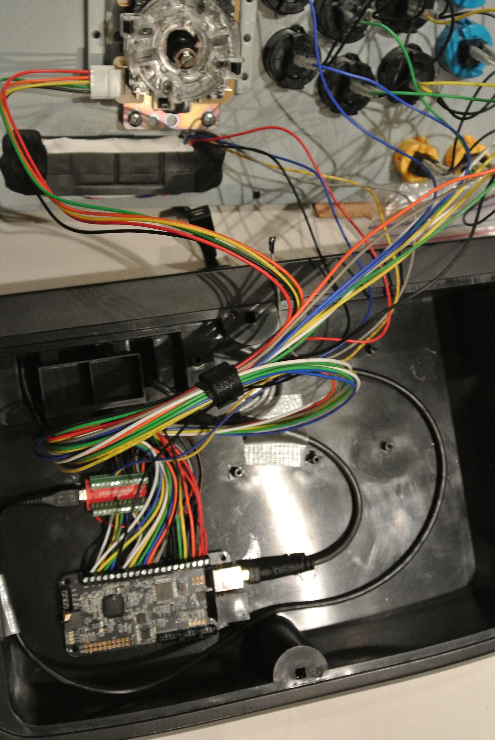
The project started out with an arcade-style joystick similar to this model: http://www.ign.com/articles/2009/02/07/hori-real-arcade-pro-ex-review . I had to replace its main control board because it was using a very fast scanning algorithm to monitor the state of each microswitch (buttons and joystick), and I didn't think I'd be able to observe it properly with a 16 MHz microcontroller. I used an Akishop PS360+, which uses a very simple pull-up resistor per switch plus common ground wire.
Once that was done, I soldered 0.1" pitch screw terminals to the back of a Pro Micro (Arduino Leonardo clone) from SparkFun and connected 14 IO pins to the 14 inputs on the PS360+ (I skipped the home button). Getting two wires into the tight screw terminals on the PS360+ was actually one of the hardest parts of this build.
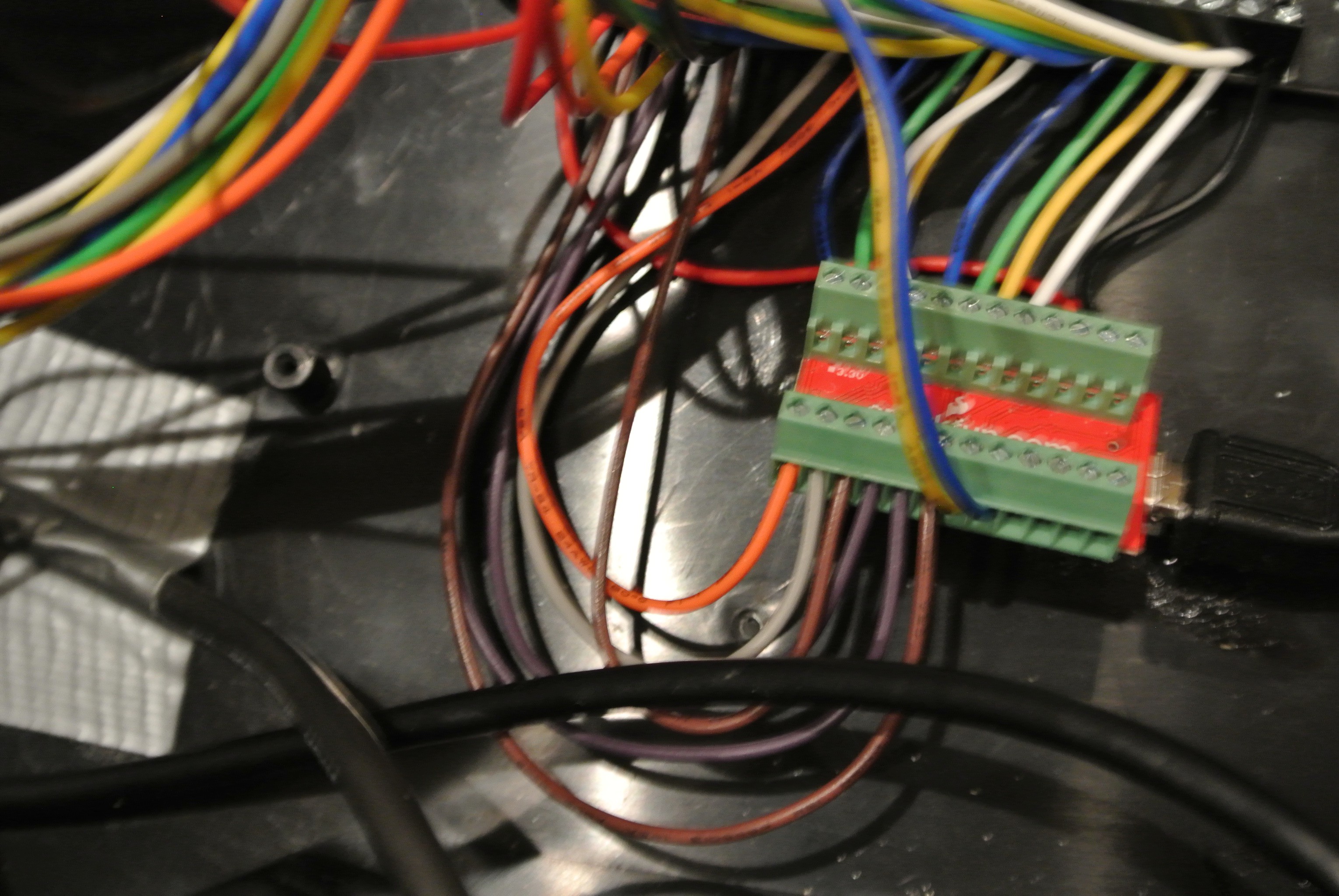
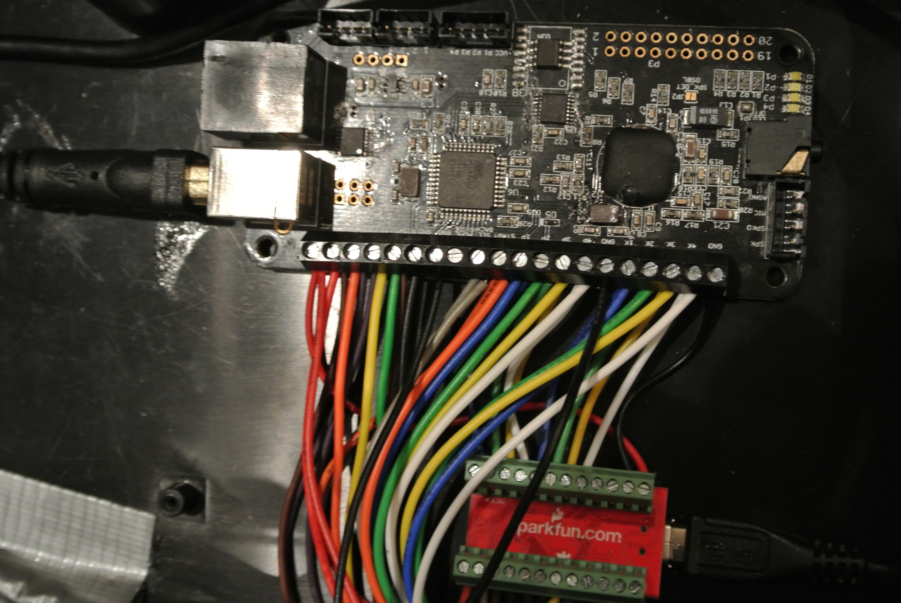
 At this point, I could observe the state of each microswitch by monitoring the input pin, or force them into a pressed state by setting the pin as a low output
Power
One issue I thought a lot about was how to power the Pro Micro. When both it and the PS360+ are plugged into USB, everything is fine (I connected only their grounds at first). But I wanted the Pro Micro to work even when only the PS360+ was plugged in. I eventually settled on connecting the PS360+ VCC with the Pro Micro's RAW input. Now, when only the PS360+ is plugged in, it provides power through the regulator on the Pro Micro, which only drops about 100 mV (it doesn't draw much current), which is well within tolerance (USB must provide at least 4.75 V, and the ATmega32U4 requires at least 4.5). When only the Pro Micro is plugged in, it powers the PS360+ through a diode, which I saw dropping about 280 mV. That's technically too much, but this isn't really a supported configuration.The one configuration I'm still a little worried about is when *both* are plugged in to two different devices (like a laptop and an XBox). However, as long as the USB busses are within about 100 mV of each other, no current should flow into either bus (which would be illegal). I'm very careful to only plug it into two devices if *both are on*. If it's plugged into one on device and one off device, it might try to drive the USB voltage on the off device. In that case, I'd be counting on the Pro Micro's fuse to avoid blowing anything up.
Display
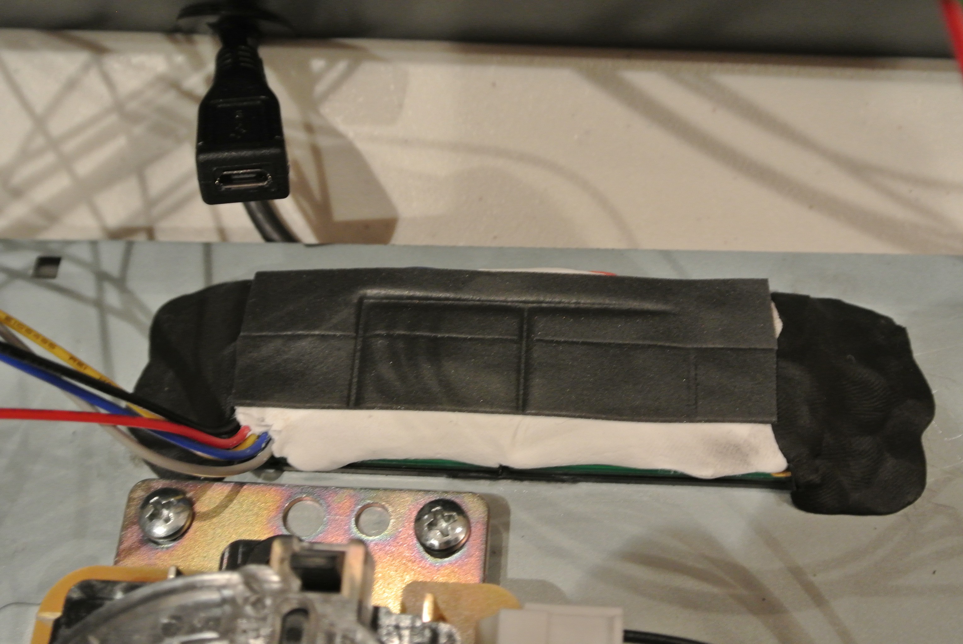
Removing the original control board left a small rectangular hole where the home button (and friends) were. It is just *perfectly* sized for this display: http://www.newhavendisplay.com/nhd0420cwag3-p-7828.html . I glued it in with a bit of super glue, then smothered the back with a bunch of sugru for extra adhesion and some foam tape to keep is pressed tightly to the plastic below. Here are pictures of the pull-up resistors for I2C communication and the reset line that I soldered directly to the back (I had nowhere else to put them!) and the final installation.
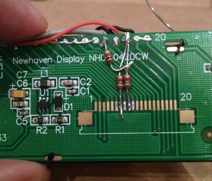
 I connected the I2C wires directly to the Pro Micro, which uses this display to (roughly!) emulate the input display in Street Fighter IV's training mode. (Video below.)
USB
The stick has 2 USB cables coming out of it: a male-A-to-male-B cable going to the PS360+ to provide a standard joystick interface, and a female-micro-B-to-male-micro-B cable going to the Pro Micro. That exposes a simple custom USB interface that allows a computer to monitor and control all of the microswitches. I wrote a simple program using Python, PyGame, and python-libusb1 to test this. (Video below.) It shows the information from the Pro Micro on the top and from the joystick API on the bottom. Keypresses are used to force-press the individual microswitches. I also ported the app to Android using its USB host support, and had to work around https://code.google.com/p/android/issues/detail?id=185219 in the process.
Videos
Input display
Host app
Android app
 worsthorse
 Chris Stratton
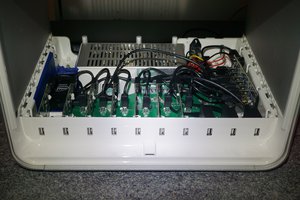
 Paul Nicholls