 Yann Guidon / YGDES
After I got an old EEPROM writer working, I started creating a multiply table with old BIOS PLCC32 chips.
However this is good only for the DIP prototype working with 5V. The 3.3V system needs to use SMD parts only.
I spent more money on modern gear and found a good deal on eBay for a TL866A universal programmer. It arrived lately ! You can guess the excitment... I'm still not sleeping ;-)
So I tried all the old BIOS chips I had around and all pass (except some weird under-marked chips from an undefined manufacturer but who cares).
Next comes the time to try the Am29LV160DB and use the fancy TSOP48 ZIF adapter. No luck. I try everything : no result. Some garbage appear but... it doesn't work.
Is the active adapter broken ? That could explain it but it's brand new...
I've turned the problem around and around in my head and no solution. Time to read the datasheet again. And...
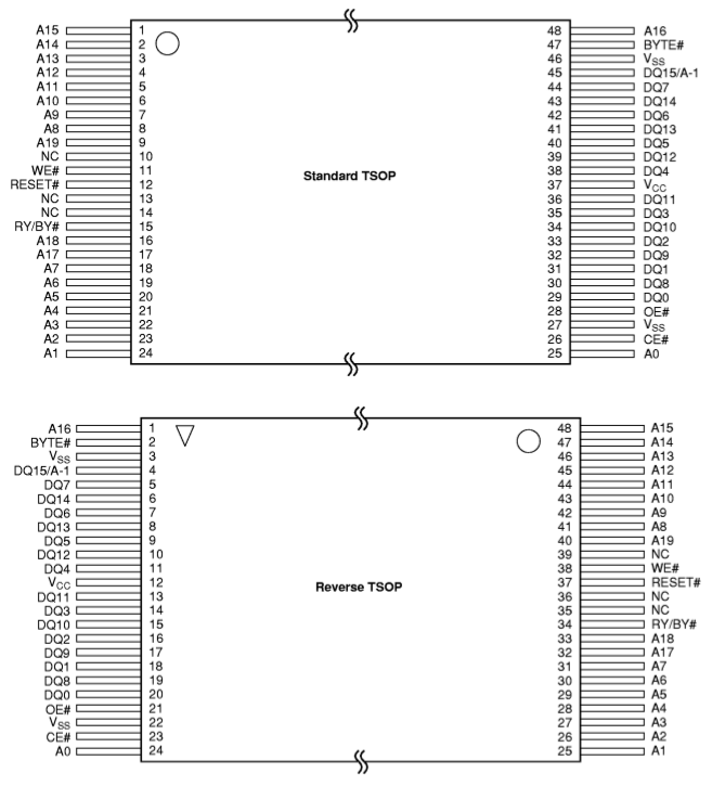
They sell the very same chip with the pinout totally reversed ?
Now that might explain why I see this unusual triangle on the topleft corner that did not ring a bell (until now).
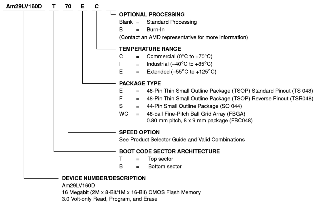
The part is more precisely : AM29LV160DB-90FC and the software only cares about AM29LV160DB. What do the next signs mean ?
The other solution is to solder another female connector on the other side of the ZIF's PCB :-D Soldering will be "interesting" because there are 2 rows...
Update
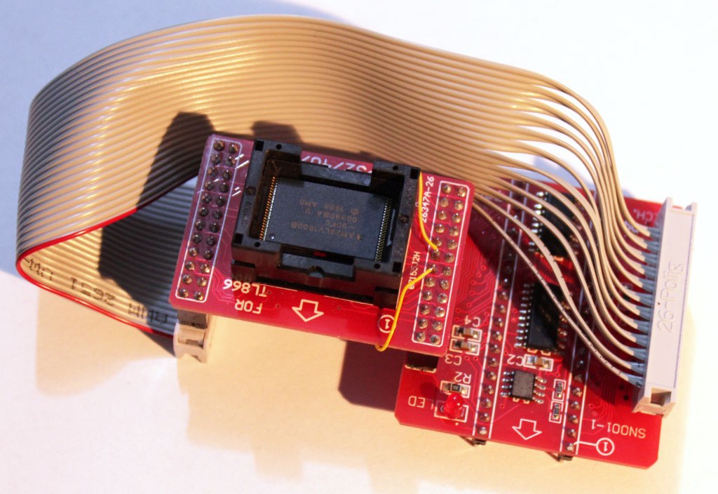
The new adapter adapter works !
It was not as easy as I thought because the naive version also reverses some pins (differently). And I broke two pads while removing the aforementioned female connectors from the ZIF board (hence the yellow patch wires). But with some twisted IDC magic, all the "guinea pig" chips have been programmed, none was even fried from the precedent attempts with the wrong connections.
I wasn't sure what to expect from the TL866A but so far, it seems to work well. I hate having to use Windows but I think the programmer will be useful in the future :-)
Discussions
Become a Hackaday.io Member
Create an account to leave a comment. Already have an account? Log In.
If the socket is connected with a ribbon cable and the odd pins are on one side of the socket while the even ones are on the opposite side, you can use a long header as a male to male adapter between 2 regular cables. This has the effect of flipping the odd pins with the even ones.
The connector guy made that mistake at work one time and I had to explain to him why. :P
Are you sure? yes | no
That's an idea :-) but I implemented an even worse idea. Fortunately the socket is wired 1-to-1 with the connector, no funny business, all the pins are correctly ordered so, as I put a connector on the other side, the signals should be perfectly reversed.
I cross my fingers...
Are you sure? yes | no
it doesn't work...
Are you sure? yes | no
there must be an inversion somewhere and I might have to make a proto PCB to adjust the pinout...
Are you sure? yes | no
Ha yes there is an inversion and it is something like what you mentioned... There are two 2x12 connectors on each side:
if the connectors were a single row, my trick (solder another connector on the other side) would work, but that mixes the pins differently......
At least now I know what's wrong :-D
Are you sure? yes | no
Hey !
now I think about it : there is only ONE adapter to do, it can be a ribbon cable. One of the edge 2x12 connector is fitted on the male header of the other side, and the ZIF's PCB has a dangling female connector. It can be connected to the unfitted connector of the main PCB with a male-to-female 2x12 ribbon cable :-)
I'll do this tomorrow...
Are you sure? yes | no
BTW The reverse pinout is for dense boards place one FLASH chip on the top side and another on the back side - the pins lines up so it is a matter of dropping vias to connect them.
Reverse Flash strikes again? :)
Are you sure? yes | no
I figured that out, as I saw the reverse pinout mentioned in the past in several datasheets. Now, I did not realise that the cheap chips I had found on ebay at that time had a reverse pinout...
I'm about to solder an adapter adapter now ;-)
Are you sure? yes | no