 Eric Hertz
This "project" [page] started as the ridiculous efforts necessary to get multi-monitors running with my hardware/software... But, realistically, it's turning into a catch-all for my ridiculous ventures (past and future) in display-hacking, in general.
Here's how this project-page started:
--------------
The short of it is: I've an old PCI card that I wanted to add to my desktop, in addition to its built-in video, so I could run multiple monitors.
The longer of it is: This old PCI card is no longer supported by my OS, so I had to hack the driver, and recompile the kernel, and several other things to get it working.
The longer-longer of it is: This old PCI card was designed for a special monitor. I long ago took this PCI card apart to get that monitor working with standard VGA, and after months of hard work I'm using that special monitor on standard-VGA, while, more recently, after over a week of hard-work I'm using that special card to drive a standard VGA monitor (dumb?). (That's in the "instructions", here).

--------------
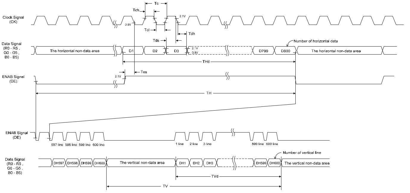
The longer-longer-longer-term idea of it is: This newly-functioning "standard-vga" monitor has FPD-Link/LVDS inside... And I happen to have an old TV board which outputs FPD-Link/LVDS at a resolution close to this monitor's... So I'm thinking about it... I'm thinking about inserting a LVDS-switch between this monitor's VGA input-board and the display's LVDS input, and attaching the TV board as yet-another-input... Composite, HDMI, ATSC, several others... Kinda ridiculous, but not entirely, considering I'm still using a CRT TV. But, more ridiculous: the TV board's closest-resolution-match is something like 1280x720, whereas the display is 1280x1024, which means *if* it works (which--from my FPD-Linking experience--isn't unlikely), there'll either be a blank portion or some repeated-info at the bottom (to be covered-up...?).
Further ridiculosities: The Tuner in that board isn't particularly strong, last I tried it... My ATSC->Composite converter gets several more stations with the same antenna. So, would I use the ATSC->Composite converter fed into this TV board that has its own in-built ATSC tuner, then feed that into this display? Ridiculous.
Maybe I should re-purpose that old 15in LCD, instead... 1024x768 is a default-res on the TV-board, anyhow... Rambling. Ah, but the 15incher has Dual-Channel LVDS, whereas, last I checked, the TV-board is Single-Channel (maybe a different mode?)... So, maybe... Finally! Another use for my Single-To-Dual Converter! I still have a functional *dead-bugged* prototype hanging on the wall... hmm...

Do I dare replace my 32in CRT with a whopping 15in LCD? Think about all the extra space! Hmm.... Or, if nothing else, it'd add two HDMI/DVI inputs and still have the VGA... nevermind composite... Third-monitor for my desktop? It's just collecting dust, now... Thoughts To Ponder.
Or there's that other 15incher... its got parallel signals, rather'n LVDS... but I do have an LVDS->parallel converter in my collection... Hmm...
Or I could rig either (or both) up with An AVR for various other project-possibilities... The ol' Binary Clock... Or a larger-screen for my logic-analyzer... (I wonder would dual-pixel be usefully-viewable for 4 channels? Maybe 5? hmmm). Still want to remove the backlight on one display and use it as a VFD-Color-Filter. And of course, there's MarioThing, which could stand to be a tiny bit larger to be more life-sized...
Then, again, there's the Wacom/Display possibility... My digitizer and display go together, 12in. The display's Dual-Channel LVDS, but I've built (and have yet to purpose) a 1chDVI->2chLVDS converter which could work with that... But I don't have a DVI video card, as yet. OTOH, I do have that old Matrox 8MB card, which has the ability for an add-on board for DVI.... the header for-which, I'm guessing, is probably parallel-signal... which means I could strip that DVI->LVDS converter of half its circuit for Parallel->LVDS (which would make it much like the "special"...
Read more »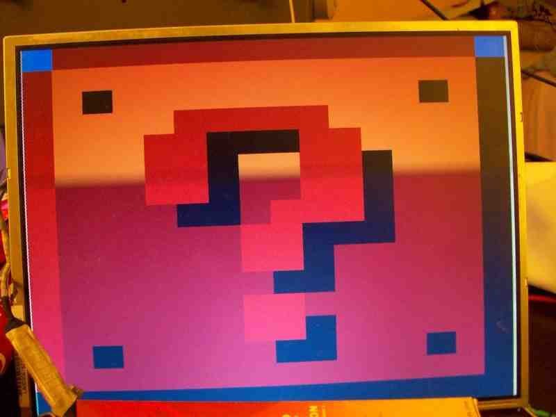
 Sitting in the laundry room atop the donation-bin...
 ogdento
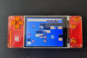
 deʃhipu
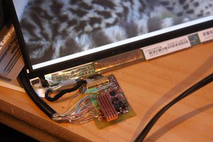
 Jared Sanson
 PK
PK