I now have the KiCad files and source code for the server and receiver units in GitHub.
The schematic and code for the receiver unit is pretty simple.
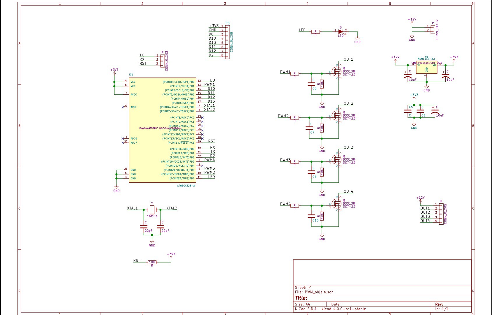
It has an Atmega328P as the microcontroller. It is connected to nRF24L01+ radio and four N-channel MOSFETS. I used the the mini version of the radio module. It's connected with a header to the PCB for easy serviceability. I also use the same header to flash the arduino bootloader to the chip. After the bootloader is flashed I use another header with TX, RX and RST pins to program new software/debug. I power the whole board with a 3.3V regulator from the 12V line. The microcontroller is running with a 16MHz crystal so it's slightly overclocked for 3.3V, but it should run fine. The PWM channels have all the same frequency. The series resistors and C7-C10 are for a possible filter on the PWM channels. At the moment the caps are unpopulated and I have 0 ohm resistors populated. 10k resistors for pulldown.
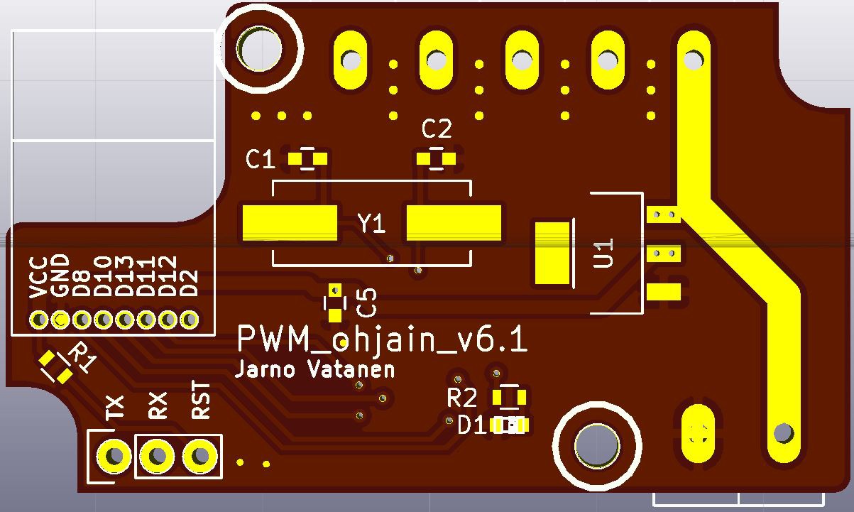
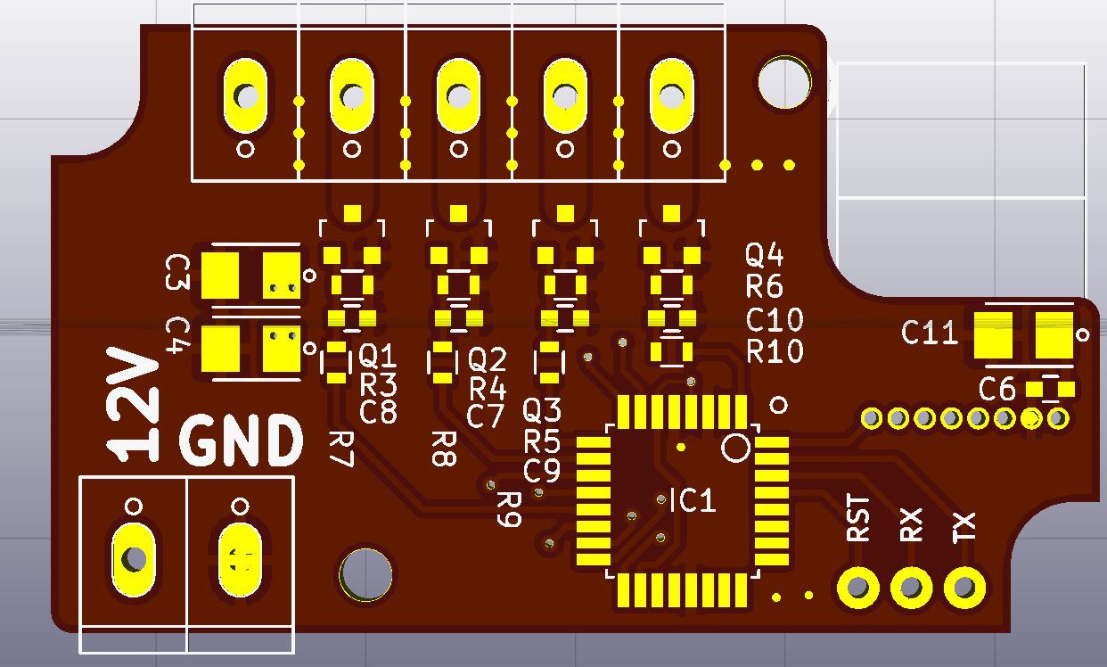
I designed the PCB to fit inside a Hammond 1551HFL/1551H case. The maximum size for a PCB inside those cases is 54x29mm, but my PCB is 50x29mm so it's cheaper to manufacture. I have one unit in a case with some cutouts made with a dremel for the connectors. I'll try to 3D print a case with ready cutouts. If it's successful, I'll publish the files also.
On the software side I use the RF24 and RF24Network libraries from maniacbug. The code is short and quite well commented, so it should be self-explanatory.
Discussions
Become a Hackaday.io Member
Create an account to leave a comment. Already have an account? Log In.