 Nuno Cruz
Features
For onboard module:
- Able to monitor Battery and Controller
- BMS is proprietary is RS232 port
- Controller is a Sevcon Gen 4 with CAN
- CAN BUS is accessed using an MCP2515 + TJ10150 module
- Able to update the display with current values and other desired variables without being limited to the expected object scale values used for current TPDOs
- WiFi connectivity, able to switch between multiple SSID''s, and act as Access Point
- 3G and RF backup for internet connectivity
- WiFi via YUN shield
- 3G via SIM800L or YUN shield with USB dongle
- RF via RFM23BP
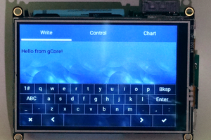
- Alternative to local display is having the goMon as an WiFi access point and allow a mobile device to open a browser and view the status
- Local display for monitoring status
- Via an Itead Nextion HMI
- Power from DC/DC (this is NOT the one available at the scooter) and 12V line
- DC/DC is a 5V 2500mA power supply
- The dual power supply will add the ability to support a local power kill switch, and be able to be waked up as soon as 12V are available
- Ignition remote kill switch
- Via relay
- Read charging current
- Using a current transformer
- Ability to disable goMon power if local battery is low
- Via relay
- Remote plug control algo via RF
- To be able to start charging, and report charged Ah and duration
- Local log record
- To SD Card or USB Stick at Yun shield
- GPS
- Using a uBlox Neo6Mv2
- Compass
- HMC5883L
- Accelerometer
- MPU6050
- Temperature
- Typical DHT11/22
For remote gateway:
- RF connectivity to onboard unit
- Using a RFM23BP, estimated range is over 10KM, or 7 floors UP
- WiFi connectivity
- Using an ESP8266
For remote plug
- RF connectivity to onboard unit
- Probably not with the RFM23BP
- Charging controlled by the onboard unit
- Via relay
Inspiration comes from scooterputer and OVMS, if you don't know them, you should check them.

 Dan Julio
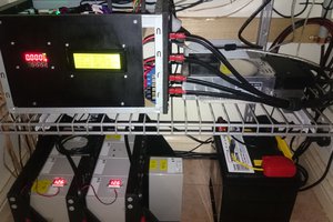

 tiefpunkt
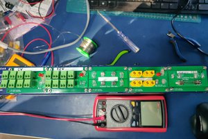
 Enki
Enki