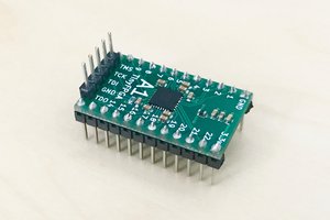
• Modeled an LED Standoff

    JNP-3R03/23/2018 at 05:01 0 comments

        After thinking about the lack of options for the missing LED standoff I decided to take the opportunity to get familiar with OpenSCAD as I've been meaning to do that for a while. As a result there's now a .stl file available on the project page for this standoff. The design files are also on Github as usual. I've not tested this as I don't have access to a 3D printer currently but if I do get access to one I may give it a go.

  • BOM cleanup

    JNP-3R03/19/2018 at 02:02 0 comments

        When I originally built this project I reused a number of parts from the original boards in the cable tester, mostly mechanical parts. This meant that my BOMs were not as complete as I'd like, so I've been working on getting a better BOM put together with part numbers for the components that need them. The new BOM files can be seen on Github and a list of components for both boards is now on this project page.

        This process involved carefully checking the mechanical drawings of the components of the components I intended to spec, and along the way I found some small measurement errors in some of my PCB footprints. I went ahead and fixed these, so there were some changes to the board layouts as well. I also took the opportunity to upload the design and updated layout files to the project page.

        The one part that has me stumped is the 10 LED standoff that is used to space the test indicator LEDs on both boards. I've been able to find all sorts of LED standoffs but none that will allow multiple LEDs to be spaced as closely as is necessary on this board. I could, of course, draw up a design to be 3D printed but I feel like that's opening up a whole other can of worms.

  • Catch up on Progress

    JNP-3R03/11/2018 at 21:04 0 comments

        I am mostly finished with this project so this log will catch up on the story from the beginning.

        I got a broken cable tester from work for free intending to repair it. After troubleshooting I found that the microcontroller was dead. Of course, the microcontroller had no markings and a non-standard pinout so a direct replacement was out of the question. I decided to take the opportunity to re-engineer the cable tester to learn about PCB design and SMD assembly.

        The original blue PCBs were the first PCBs I designed and ordered myself. Assembly with the SMD components was easier than expected and after fixing a few mistakes I was able to get the board running. Unfortunately, I had confused the drain and source on the source MOSFETs in the design so they could not turn off (the internal diode runs the opposite way in P-Channel MOSFETs compared to N-channel). This caused excessive current consumption (I could watch the battery voltage sag in real time!).

        I decided rather than cutting tracks and bodge-wiring all nine MOSFETs I would just order another board, and, since another board revision was needed anyway, I would go ahead and design a new board for the remote end. This also means that my design can be used stand alone without needing the remote end of the original tester. Fortunately the assembly of the second set of boards went well and I now have a functional cable tester. I just finished with some clean up of the design and at this point most of what's left is documentation and writing up the project for others.