 engunneer
MakerMod is a connection interface for electronics projects that breaks you free from your development platform and lets you branch out as needed to the right environment for your project.
What do all of these development systems have in common?
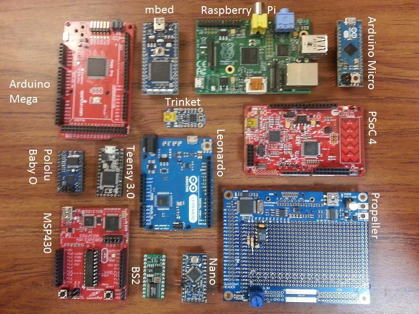
At first glance, not much. Some run on Arduino, others on Linux, and others allow you to program the raw hardware. Some are fast, some are slow. One has 26 bytes of RAM. Now mentally add to the picture all the other great platforms that are out there (e.g. Beaglebone Black, Mojo, Papillio, STM32, etc.)
On second glance, however, these are all basically the same. They have GPIO, serial ports, I2C interfaces, SPI interfaces. Some have great options for shields/capes/hats (Generically, shields), Others require a bit of soldering or work well with a breadboard.
The problem is that many of these shields might not be compatible with each other, and all are locked into a form factor. Many systems have adopted the Arduino shield layout for their connection system, but they have the same inherent problems. Will your Motor shield from Vendor A work with your WiFi shield from Vendor B? Will they even stack properly? Do they both use the same misaligned header spacing from the original Arduino?
The second driving factor behind this project is portability. If you design a cool project on one platform, and then decide you need an upgrade to a more powerful development environment, you don't need to re-purchase any of the peripheral modules. Simply plug them into your new host, write some new code using equivalent libraries, and off you go.
My solution to this problem is to adapt each major (and minor!) development platform to a common standard connection format.

How do I plan to avoid this obviously relevant xkcd? Easy. I'm not creating a new universal standard, and I don't assume it will cover everyone's use cases. I'm porting an existing standard over from high-end FPGA development platforms that will fit well with many development environments, even at the hobbyist level. Digilent did a great job with the license, as well, meaning this idea is available to everyone without much effort. MakerMod is designed to not use the PMod name, just the interface specification.
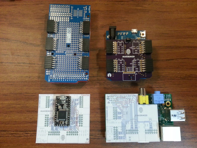
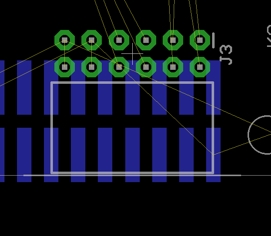
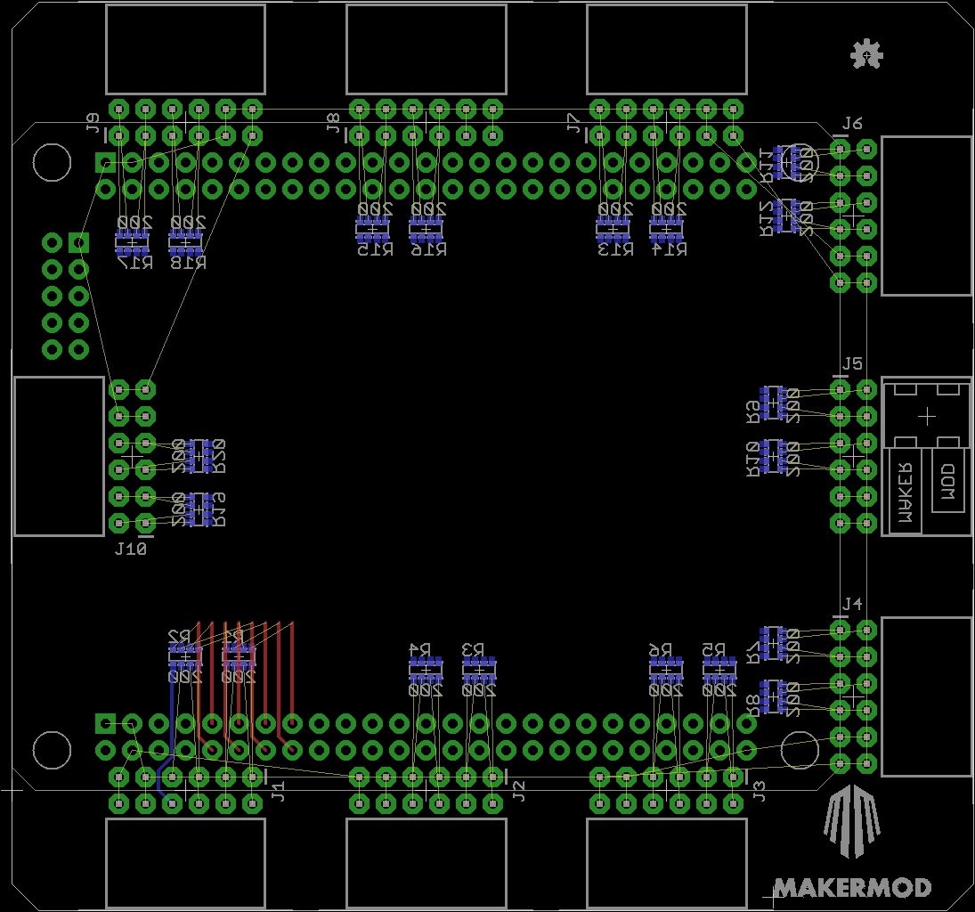
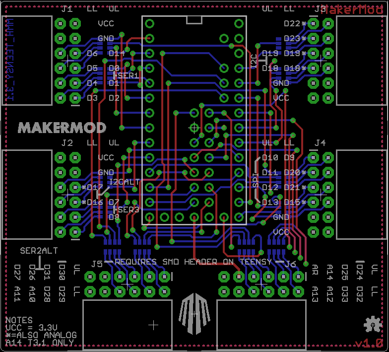
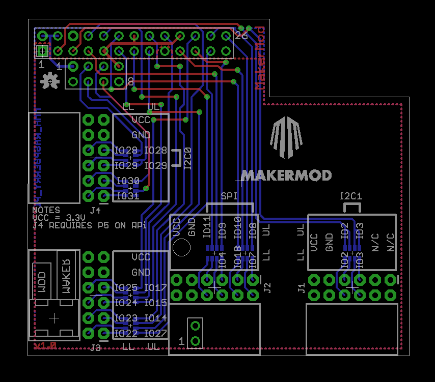
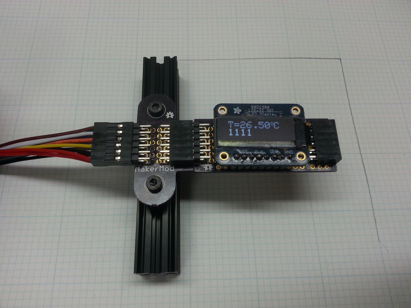
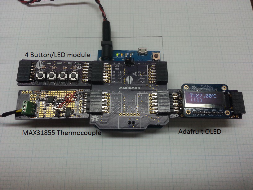
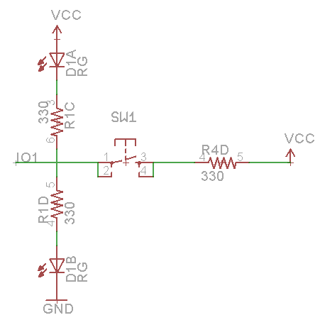
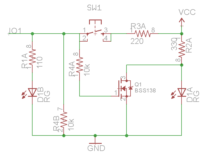
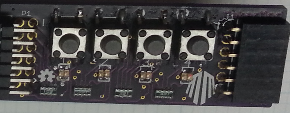
Since most of the common hobbyist platforms are not FPGAs, I am taking special care to make sure that each MakerMod Host adapter has the most common interfaces broken out from the host to the MakerMod ports. These special ports (like SPI or I2C) are indicated on the silkscreen in addition to the raw IO pin names.
Of course, I am tweaking things a bit. The PMod standard doesn't have a specification for analog signals, but it is otherwise generally useful. I'm extending some of the standard ports to include helpful features like SPI daisy chaining for Chip Select, and adapter modules to other common connections. In addition, I'm not always using all the pins in exactly the same way as the original spec, but the existing line of modules should work on most platforms, and many MakerMod modules will work on FPGA platforms (and others, like ChipKit) that already support PMod.
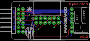
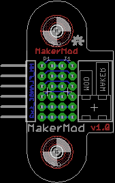
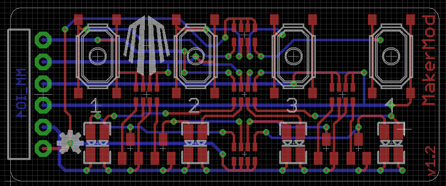
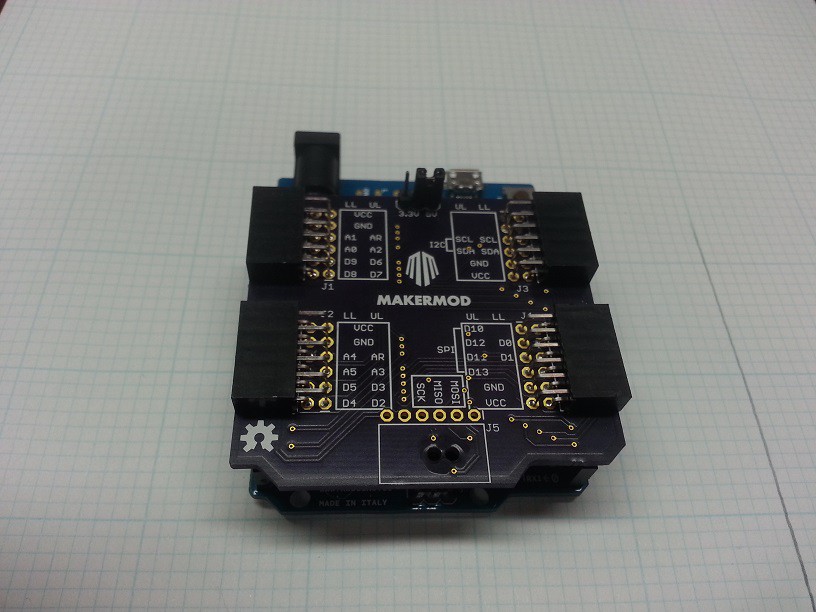
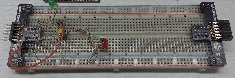
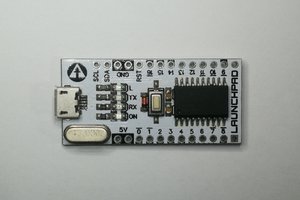
I have a list of 23 or so platforms that I'd like to support, and I'm always looking for more. I've already developed Host adapter plates for Arduino, Rasberry Pi (B) and Teensy 3. The Arduino Mega shown was my first shot to get a feel for the overall size and shape.
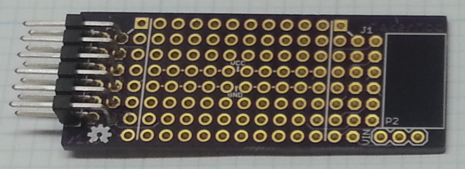
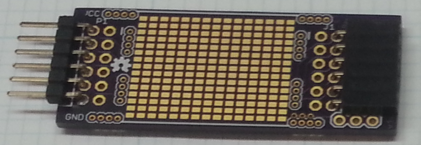
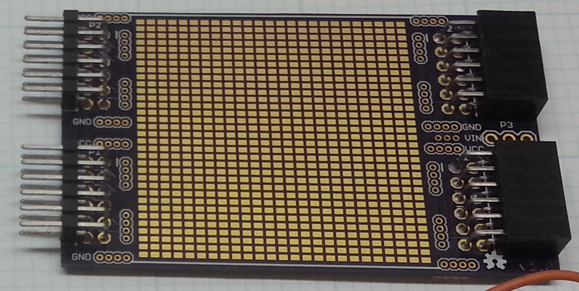
I also have a list of over 50 MakerMod modules that I'm planning to try, including some prototyping modules I have already developed for breadboard, SMD and PTH prototyping.
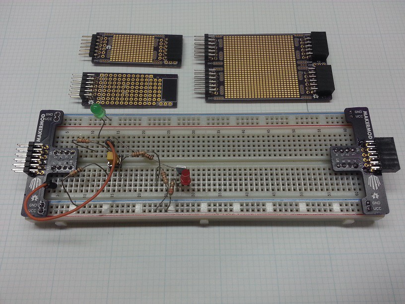
Maker modules and host adapters will all be OSHW (currently in Eagle 6.6 format, though that might change if Altium ever releases their free version), and will leverage many of the great libraries for awesome maker companies like adafruit and sparkfun, and I will also develop and release libraries for new MakerMod modules as needed.
Of course, each module will have multiple libraries, since you can plug them into any development platform...
Read more »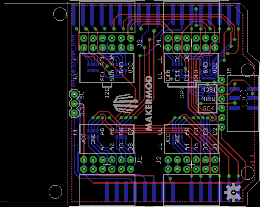

 Nicolò
 Jarrett
 Clyde D. Corpuz