0%
0%
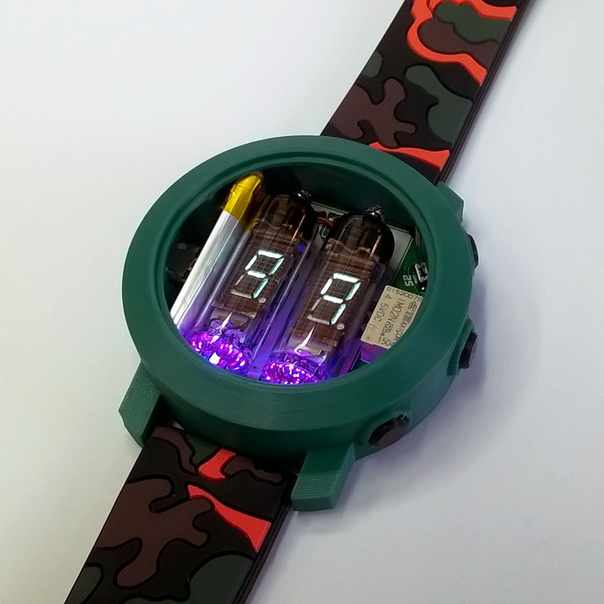
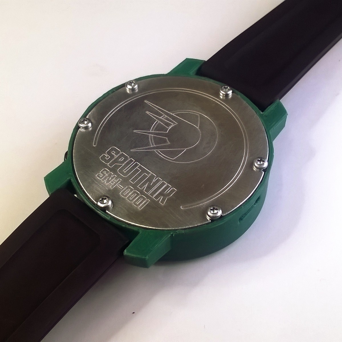
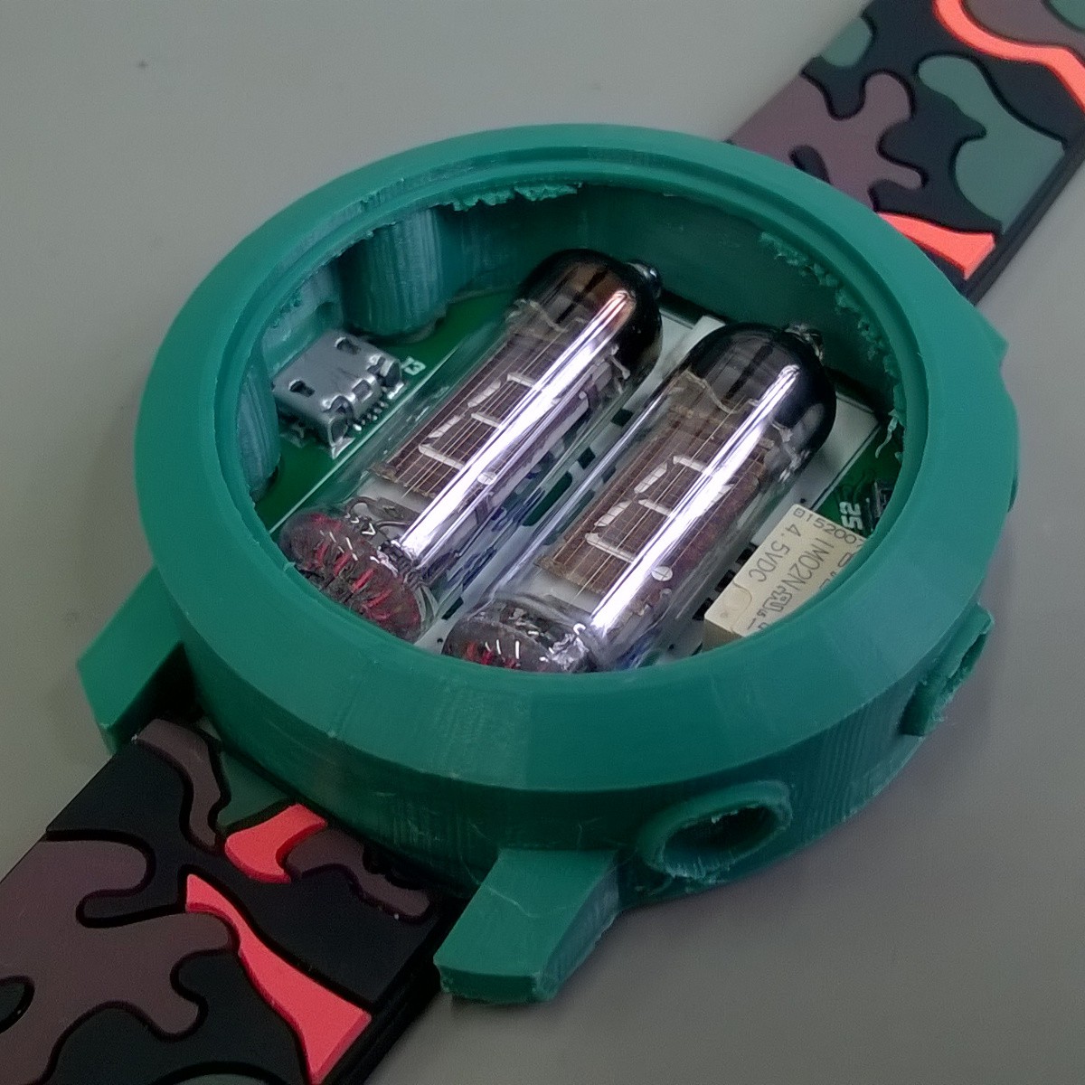
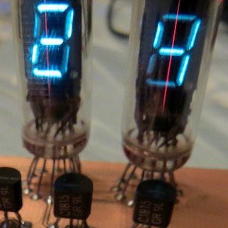
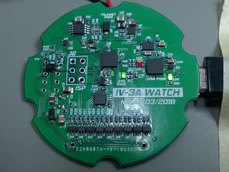
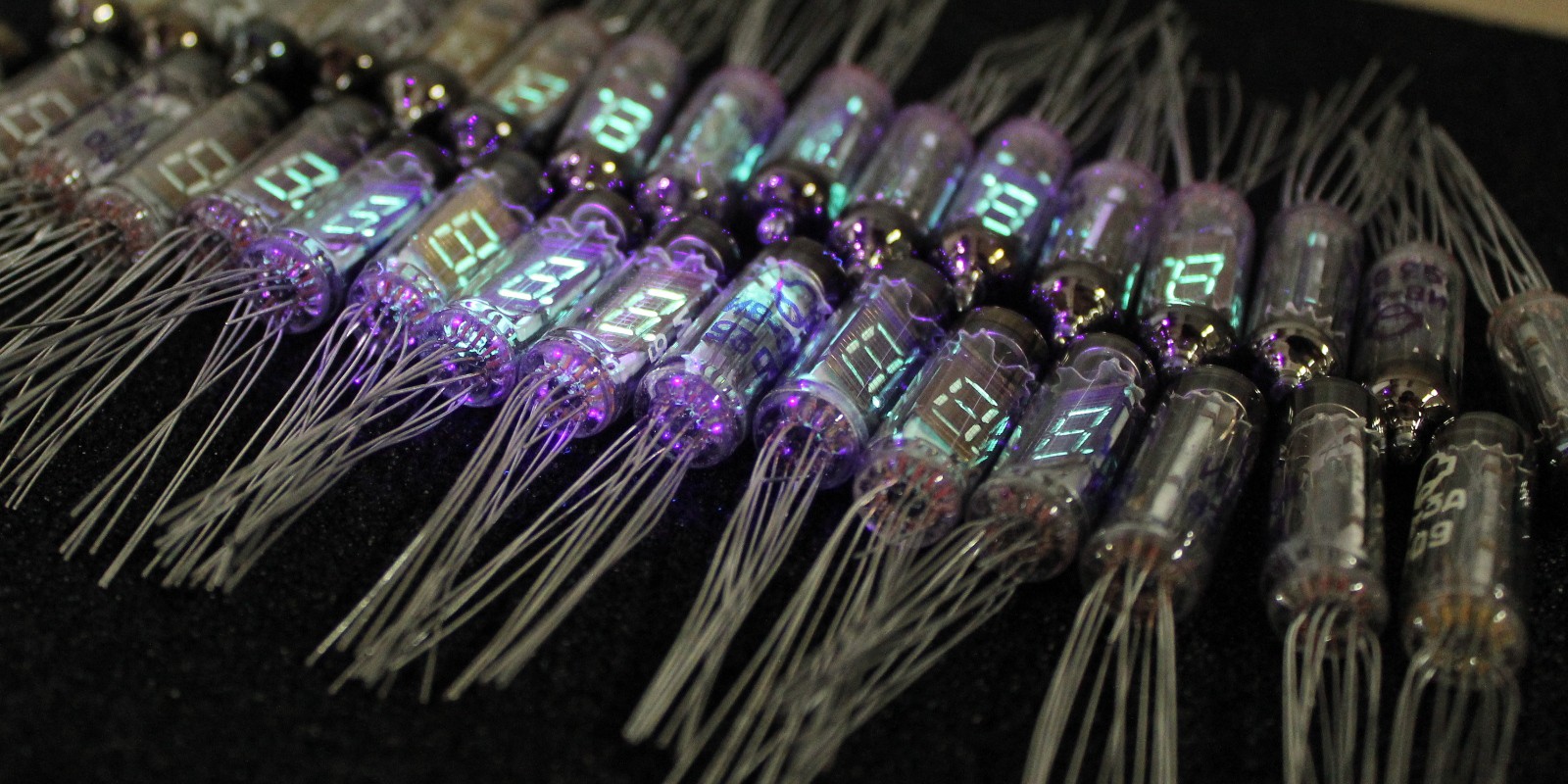
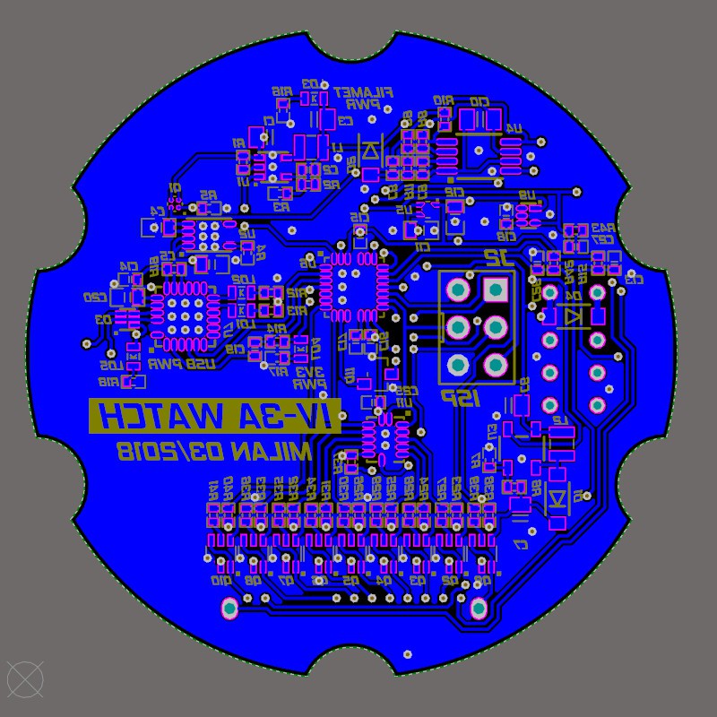
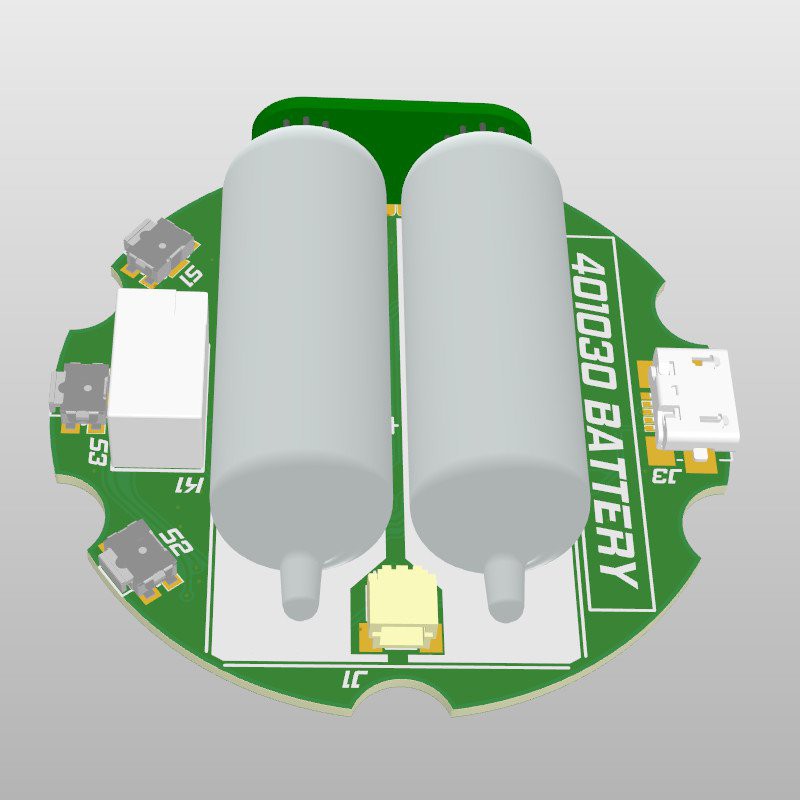
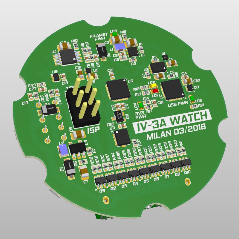
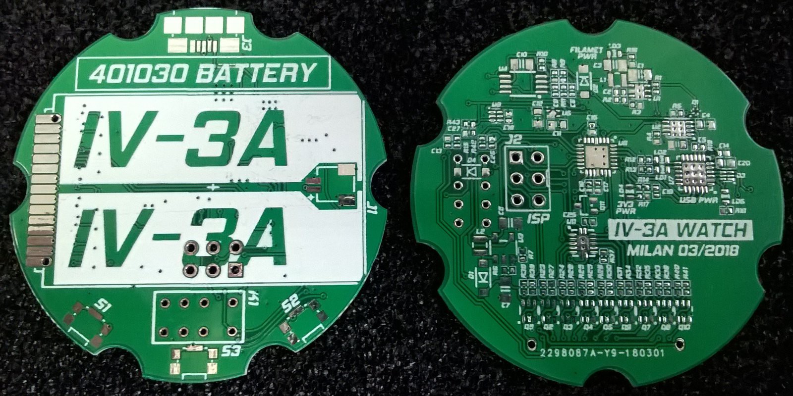
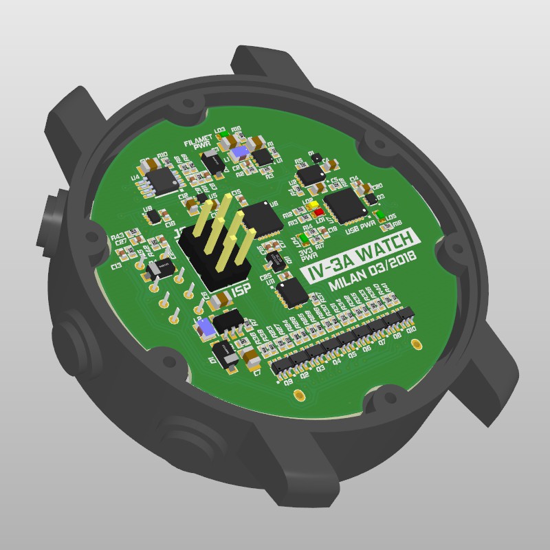
OSH VFD Watch
Open source vacuum fluorescent display watch.
 Mile
MileBecome a Hackaday.io member
Already have an account? Log in.
Just one more thing
To make the experience fit your profile, pick a username and tell us what interests you.
Pick an awesome username
hackaday.io/
Your profile's URL: hackaday.io/username. Max 25 alphanumeric characters.
Pick a few interests
Projects that share your interests
People that share your interests


 Marius Taciuc
 jaromir.sukuba
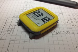
 Max.K
Max.K
 DrYerzinia
реле в качестве тикалки - гениально! попробую повторить проект. спасибо за схемы