 Alex
AlexIdea besed on my #reDOT_smart and #reDOT . But with a approach to crate bigger "strings" of Matrixes to Display Strings. I am thinking about two components:
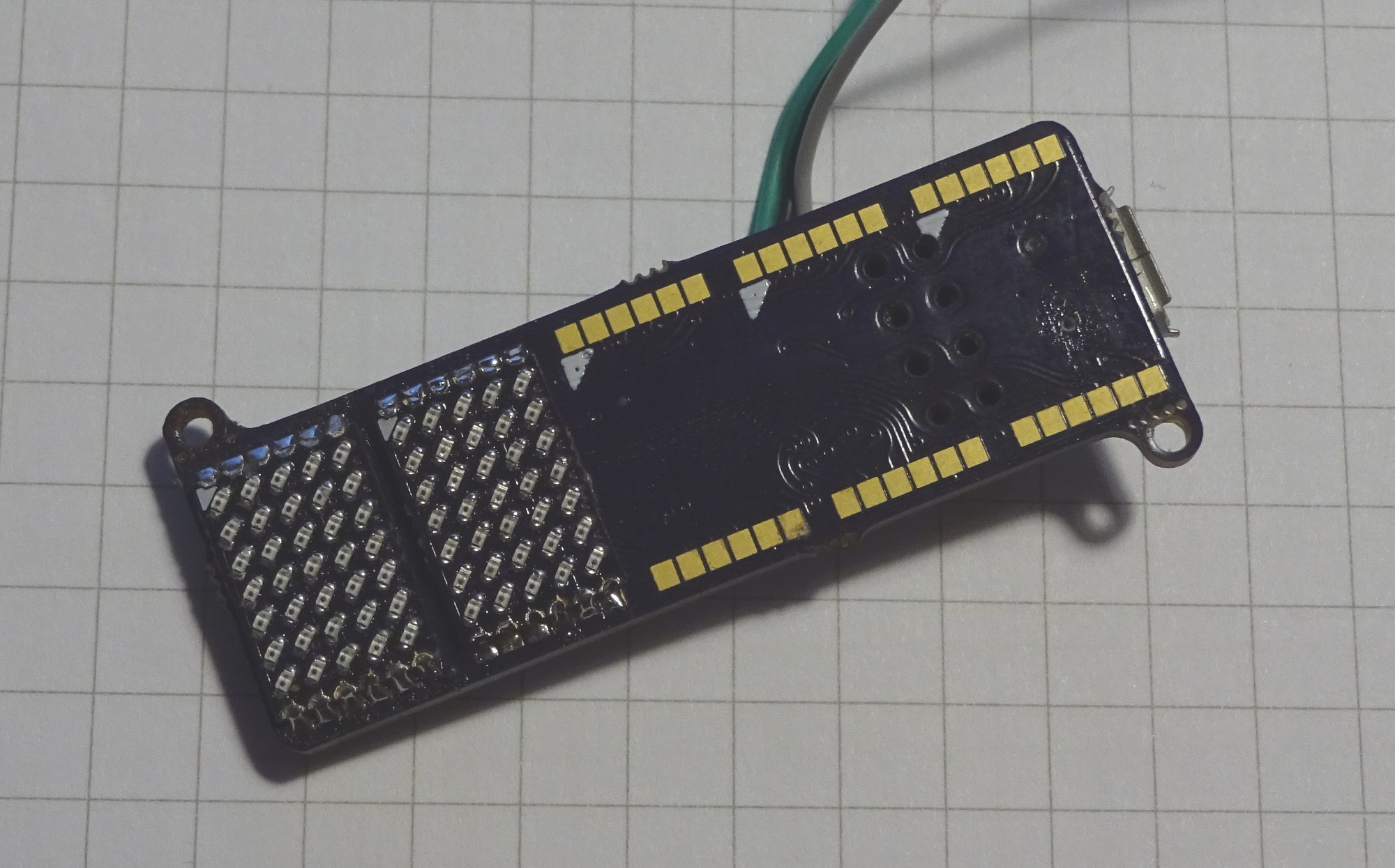
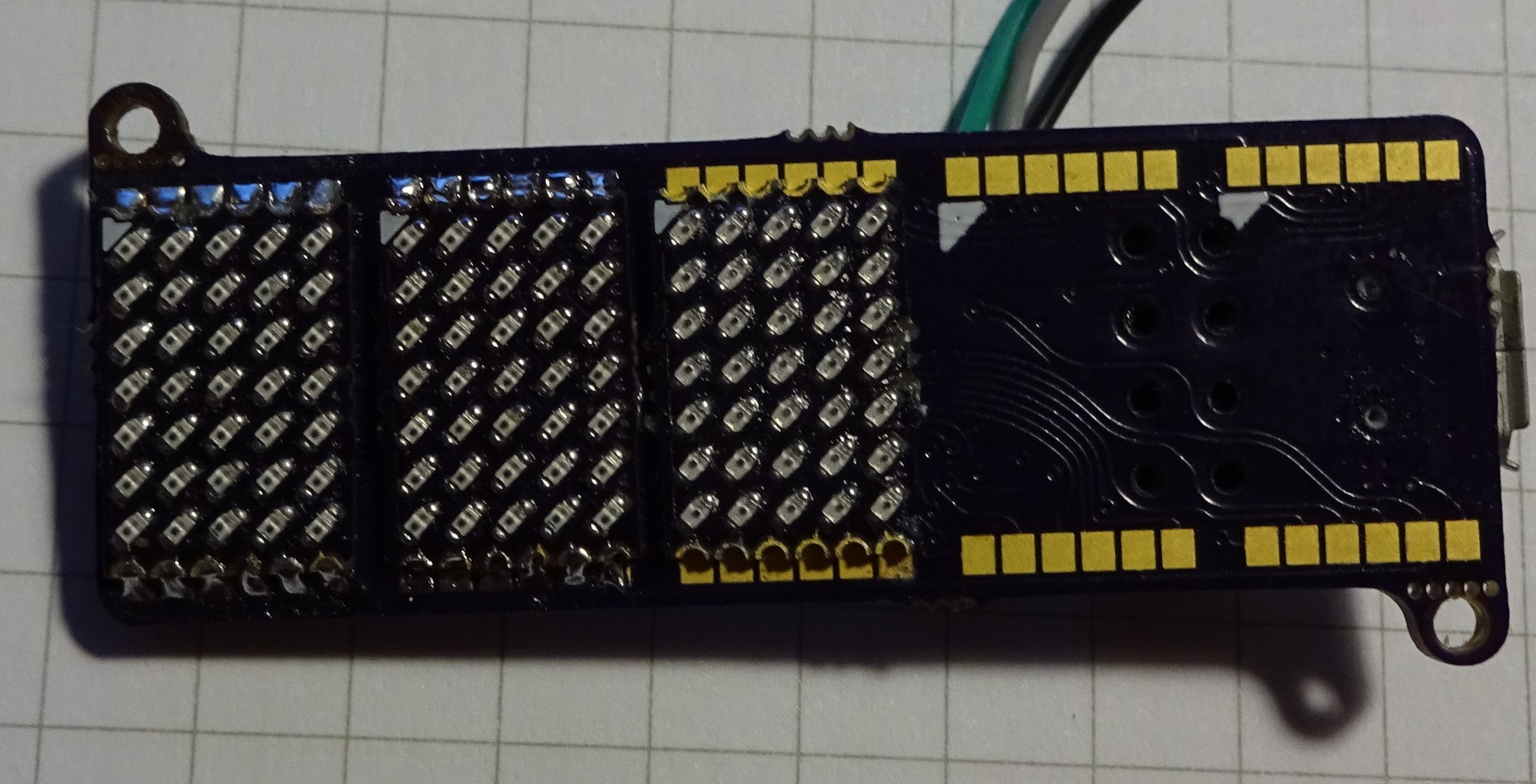
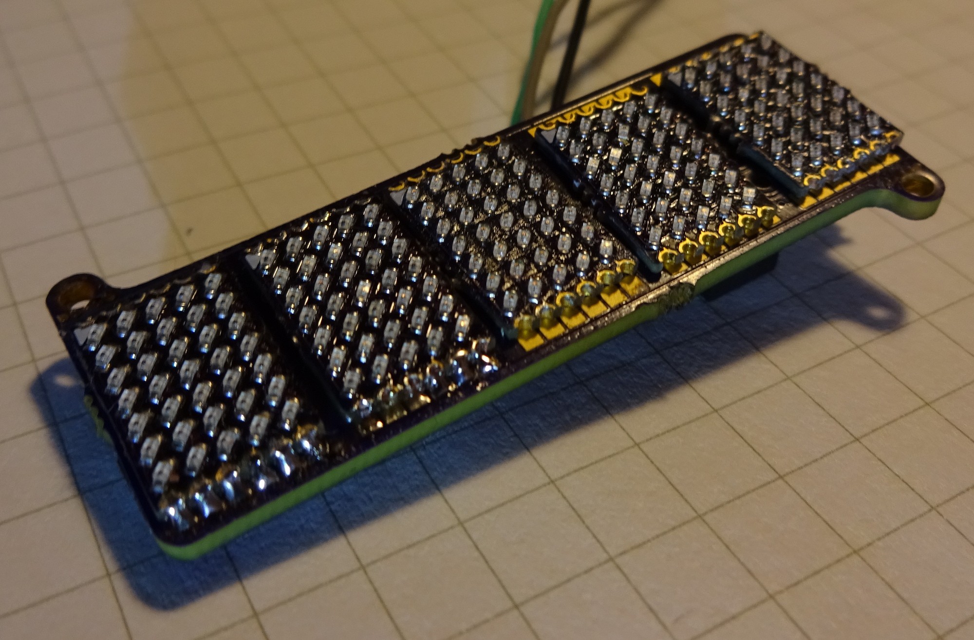
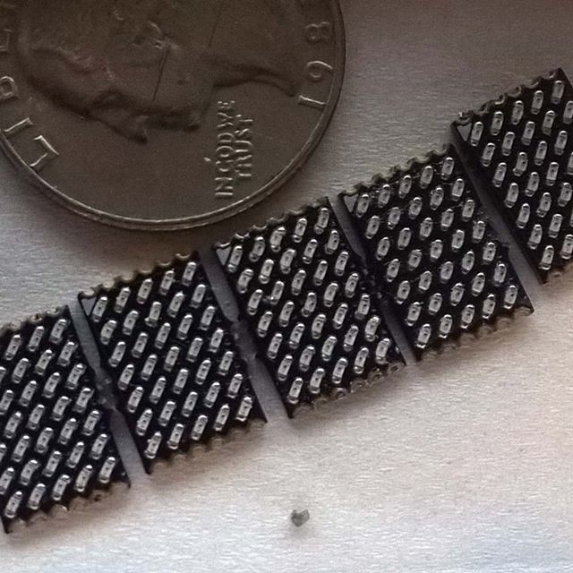
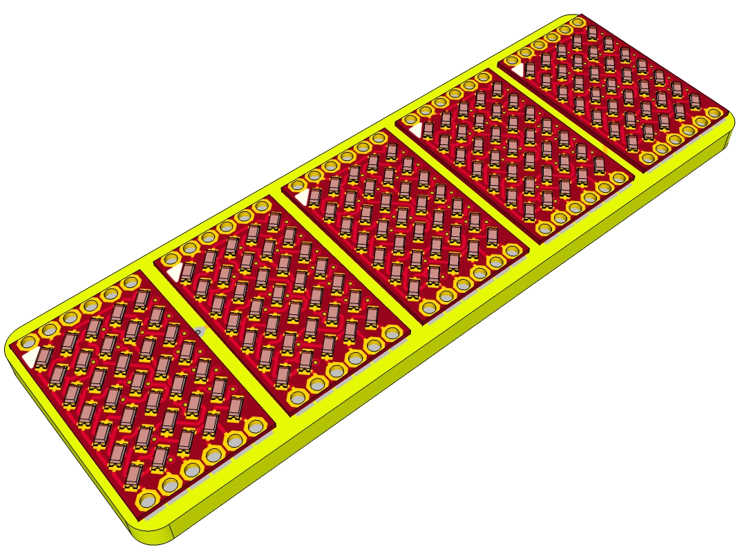
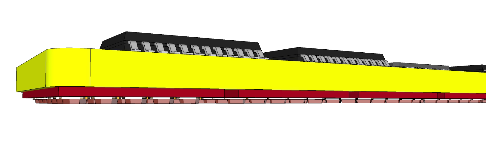
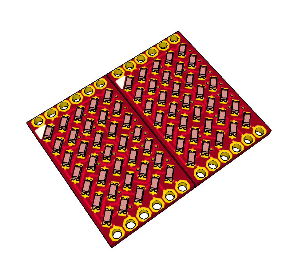
- 5x7 Matrix Board: One PCB with one Matrix on it. With castellated holes at the edge to solder it on the main board.
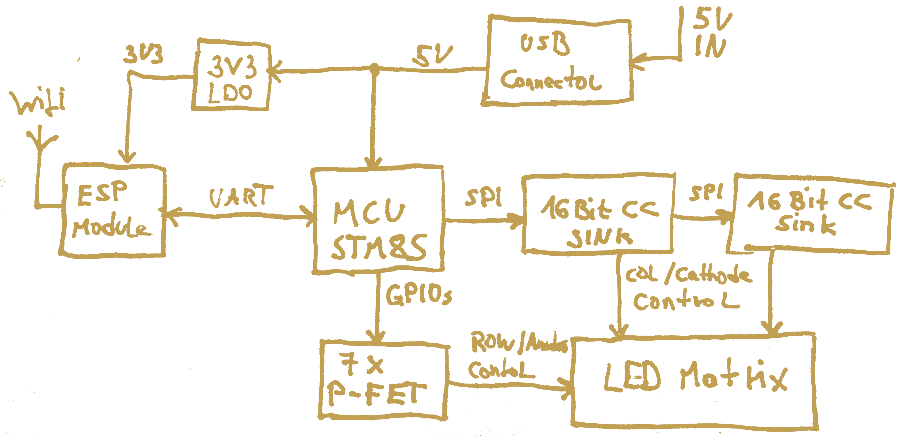
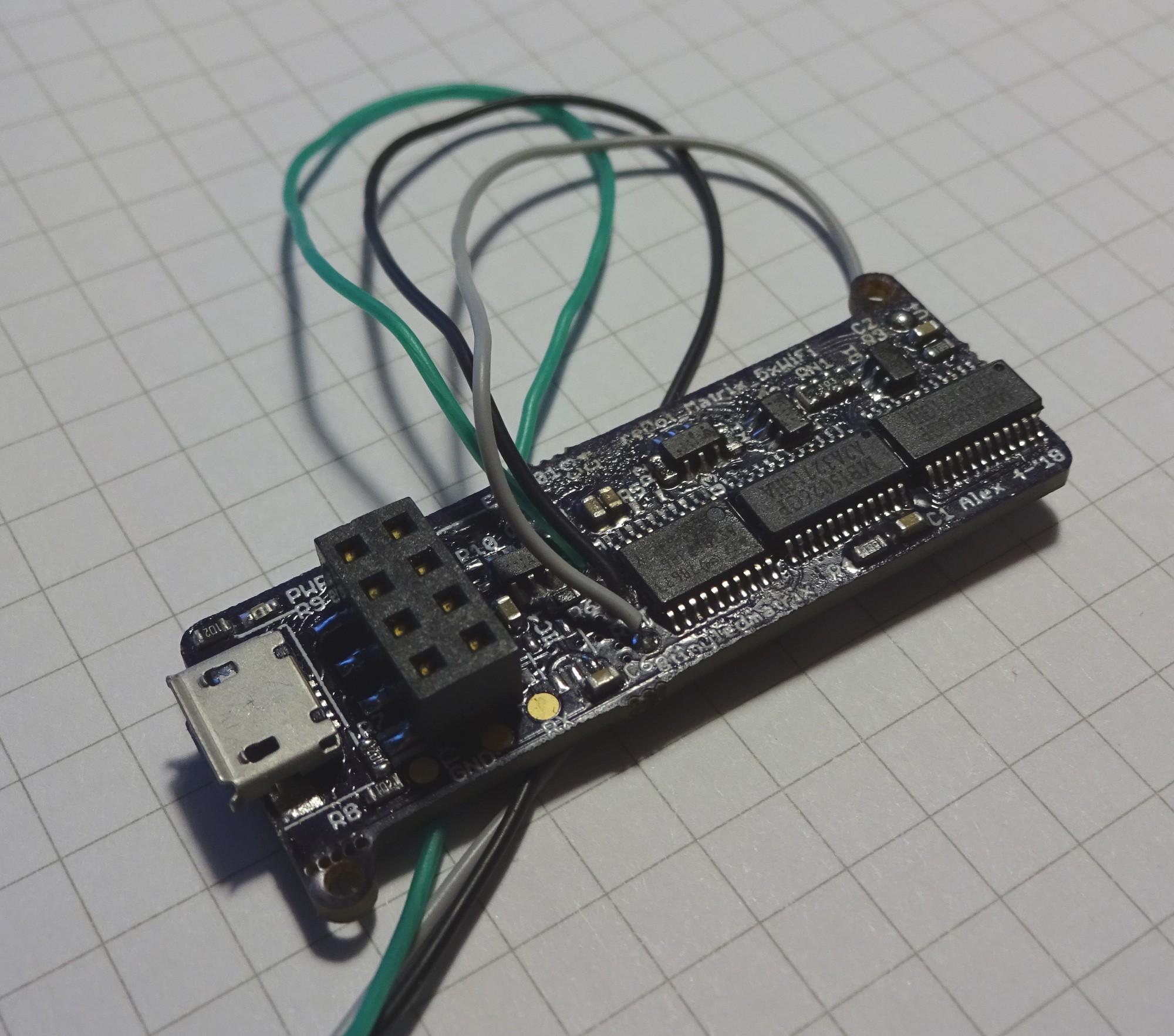
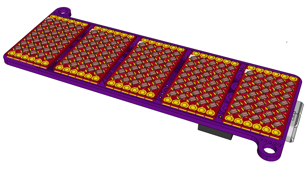
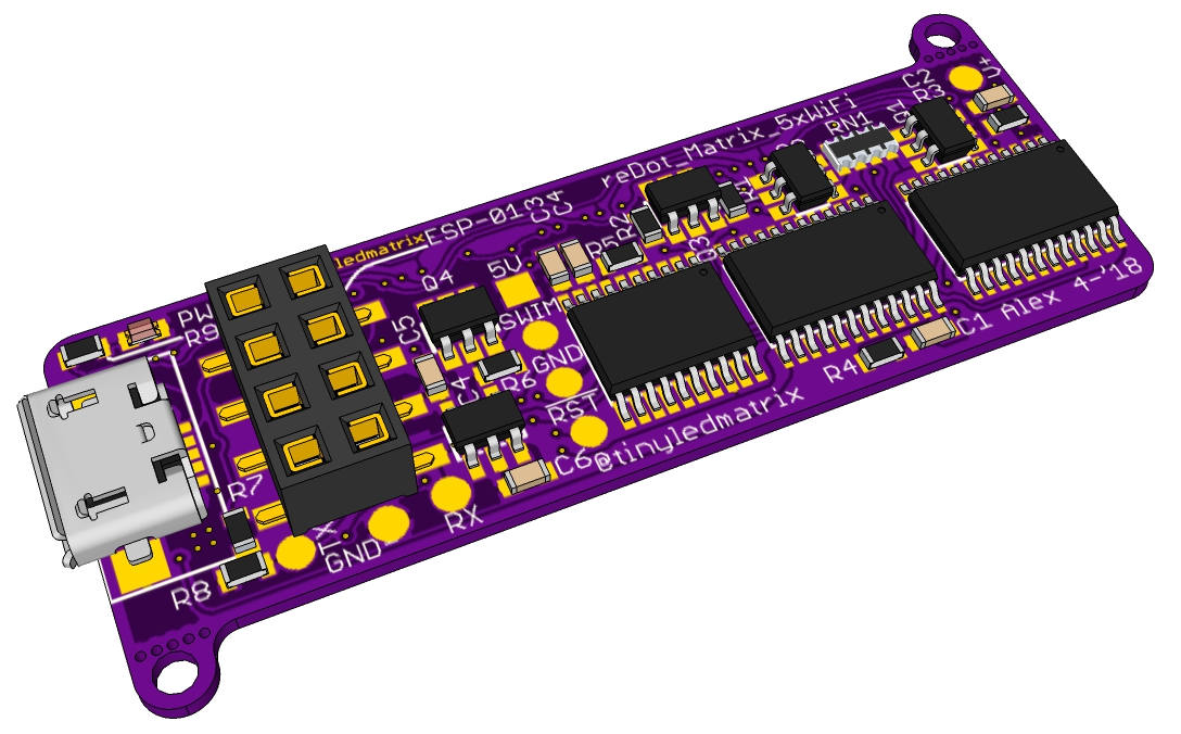
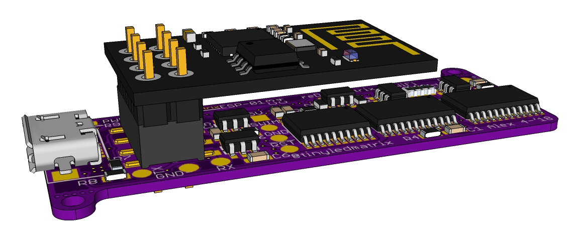
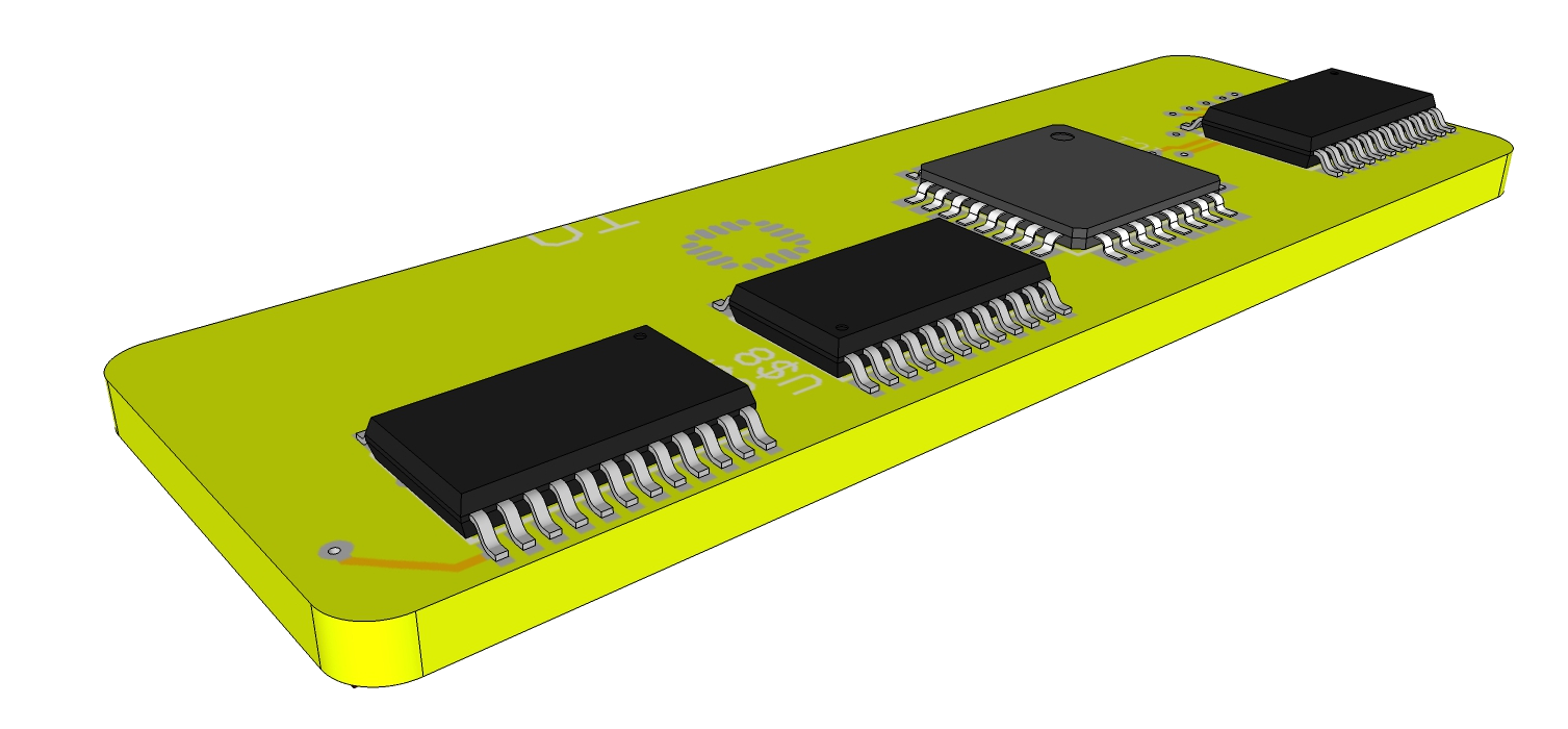
- Main board: Board with Controller, maybe some shift registers, drivers, interface and so on. 5 or 9 Matrix boards will get soldered on this board.
Main Milestones:
- Design and order 5x7 Matrix Board.
- Assamble the Matrixboard and test it
- Design Main board
- choose a Microcontroller
- Define Interface: Uart?
- chose LED-Matrix driving scheme
- Decide how man Matrixes per Mainboard
- Order Main board
- Assemble everything and show some ideas for use cases (I do have already one specific in mind, more later)

 C. Scott Ananian
 Brian Lough
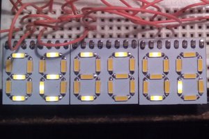
 Yann Guidon / YGDES
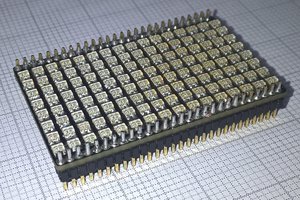
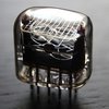
Woah! They look super neat!
Might buy some just for fun! (I have a project in need of a retro display like this, but it has to be bigger (20x80mm), but they look really cool nonetheless.