This project uses two RC circuits, one implemented as a timer, and one as part of an oscillator in order to obtain both a fixed duration for a strobe as well as a strobe frequency. Rather than use a 555, I used a quad NAND and a handful of discretes. The resulting circuit allows me to adjust the strobe duration and frequency to whatever I please by adjusting the trimpots visible on the back of the assembly.
To enclose the board, I tried a method in which all components are on the top layer of a "base board," a mid board of the same dimensions has a cutout for the components on the board below, and a final board sits on top to cover all except the trimpots. The three boards are mechanically affixed by filling large aligned vias which are around the perimeter of the boards. The result is a very cheap, durable, and aesthetically pleasing assembly. I'm not aware of any other enclosure methods which would still allow for trimpot access, besides a 3D printed case.
GIF of strobe in action on my motorcycle, note that the framerate of the GIF and my camera did not align so the light may appear to pulse infrequently, rest assured in person it looks flawless!
I'm still playing with values of R5 and R1 to get the optimal range of frequencies and delays, I will update once I've found a pair I like. I've had some requests to make some of these to sell, let me know if you're interested and it might just happen!
 Patrick Chwalek
 anfroholic
 morgan
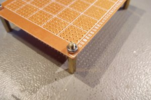
 Morgenkaff