 adria.junyent-ferre
The goal was to build a cheap circuit that would play a small audio file in an infinite loop. I could have used one of those postcard circuits they sell on Ebay and make my life thousand times easier but what would be the fun in that?
The project required designing and building several elements that deserve separate descriptions:
- An 8 bit parallel DAC.
- A headphone amplifier salvaged from a CD drive.
- An adapter board to interface a 3.3V SPI flash memory salvaged from the controller board of a CD drive to an Atmel microcontroller from an Arduino board.
On the software side, I also needed to write the following code:
- An Arduino sketch to read the SPI flash and play the audio through the 8 bit DAC in an infinite loop.
- A small program to turn an audio file into the binary that goes in the SPI flash memory.
Current state: as of now, all parts are working but I still need to adapt a few things to make the software run in an Arduino Pro Mini rather than an Arduino Duemilanova and fit everything in its final enclosure. I started making this more than one year ago so I thought it was the time to write down what I did so I don't forget.
Design and build details are described below:
An 8 bit parallel DAC
In order to play the audio, the Arduino needs a way to generate an analogue signal (Digital to Analog Conversion). This could be done using a dedicated DAC IC but as the performance expectations here were very low, I chose to make my own DAC. There are two very popular solutions for that: generating a pulse-width-modulated (PWM) signal followed by a low-pass filter (e.g. like this) or using multiple pins to produce a staircase waveform using a resistor ladder, which is what I chose to do. Note: in both cases, a high-pass filter is needed to remove the DC voltage offset of the output. This can be done using a series-connected capacitor, in my design this is was done in the headphone amplifier circuit.
A resistor-ladder DAC is a series of resistors combined together to give different weight to different digital inputs. It can be extended to any number of bits, for 8 bits it looks like this:
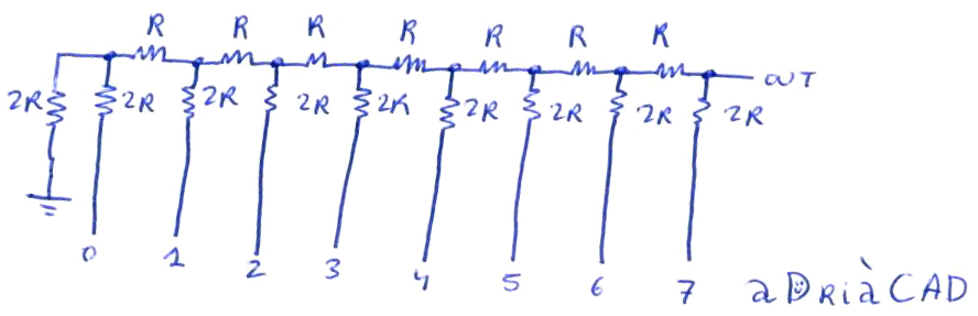
Understanding how this circuit works is relatively easy (the best way is to start by analysing a simple case with 2 inputs). Here's the solution for the 8-bit case: I used nodal analysis applied to all the "upper" nodes (the terminals of the R resistors) and rearranged the resulting system of linear equations in matrix form. The matrix is quite sparse and the system can be easily solved by hand. Nevertheless, I produced some Maxima code to do it brute-force. You can test the code using wxMaxima in your computer or by pasting it in one of the online Maxima services available (e.g. this one):
M:matrix([2,-1,0,0,0,0,0,0],[-1,5/2,-1,0,0,0,0,0],[0,-1,5/2,-1,0,0,0,0],[0,0,-1,5/2,-1,0,0,0],[0,0,0,-1,5/2,-1,0,0],[0,0,0,0,-1,5/2,-1,0],[0,0,0,0,0,-1,5/2,-1],[0,0,0,0,0,0,-1,3/2]);


sol:transpose(matrix([Vo0,vo1,vo2,vo3,vo4,vo5,vo6,vo7]))=expand(invert(M).transpose(matrix([Vi0,vi1,vi2,vi3,vi4,vi5,vi6,vi7]))/2);


solmax:transpose(matrix([Vo0,vo1,vo2,vo3,vo4,vo5,vo6,vo7]))=expand(invert(M).transpose(matrix([5,5,5,5,5,5,5,5]))/2);


if numer#false then numer:false else numer:true;


solmax:transpose(matrix([Vo0,vo1,vo2,vo3,vo4,vo5,vo6,vo7]))=expand(invert(M).transpose(matrix([5,5,5,5,5,5,5,5]))/2);
The value of R must be chosen to not be too low to draw too much power from the inputs (specially in pin 0, where the resistance to ground is just 4·R) and not too high to allow the amplifier stage distort the voltage in case it draws some current from its input. I chose a value of 2·R equal 2.2 kOhm which seemed to work well. I made the R resistors by putting two 2·R resistors in parallel and crammed a small perfboard:
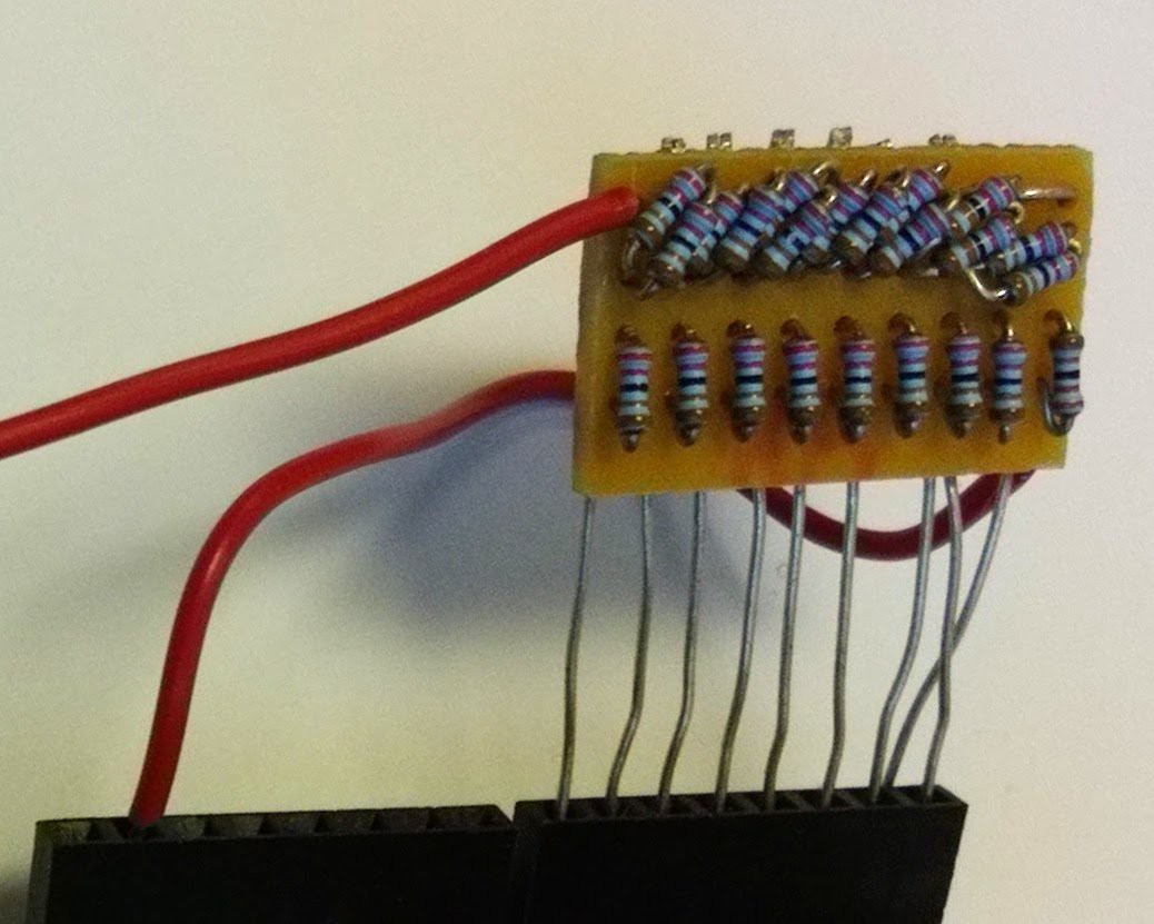
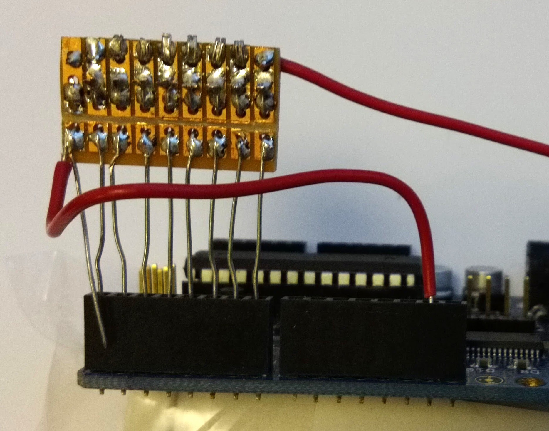
I did a few initial tests using an Arduino Duemilanova. I connected the ladder to pins 0 to 7 of the Arduino (plus ground in the lower red wire in the picture). The output voltage of the ladder is obtained from the end close to pin 7 (the most significant bit). The best way to test if the ladder does the job is to sweep the value written to pins 0 to 7 (which correspond to Port D of the Atmel 328) to be a binary number between 0 and 255. This can be done manually one value at the time or by using a sketch to sweep the value. Once I was happy with the result I made a sketch that would output a sine wave, the code can be found in Pastebin.
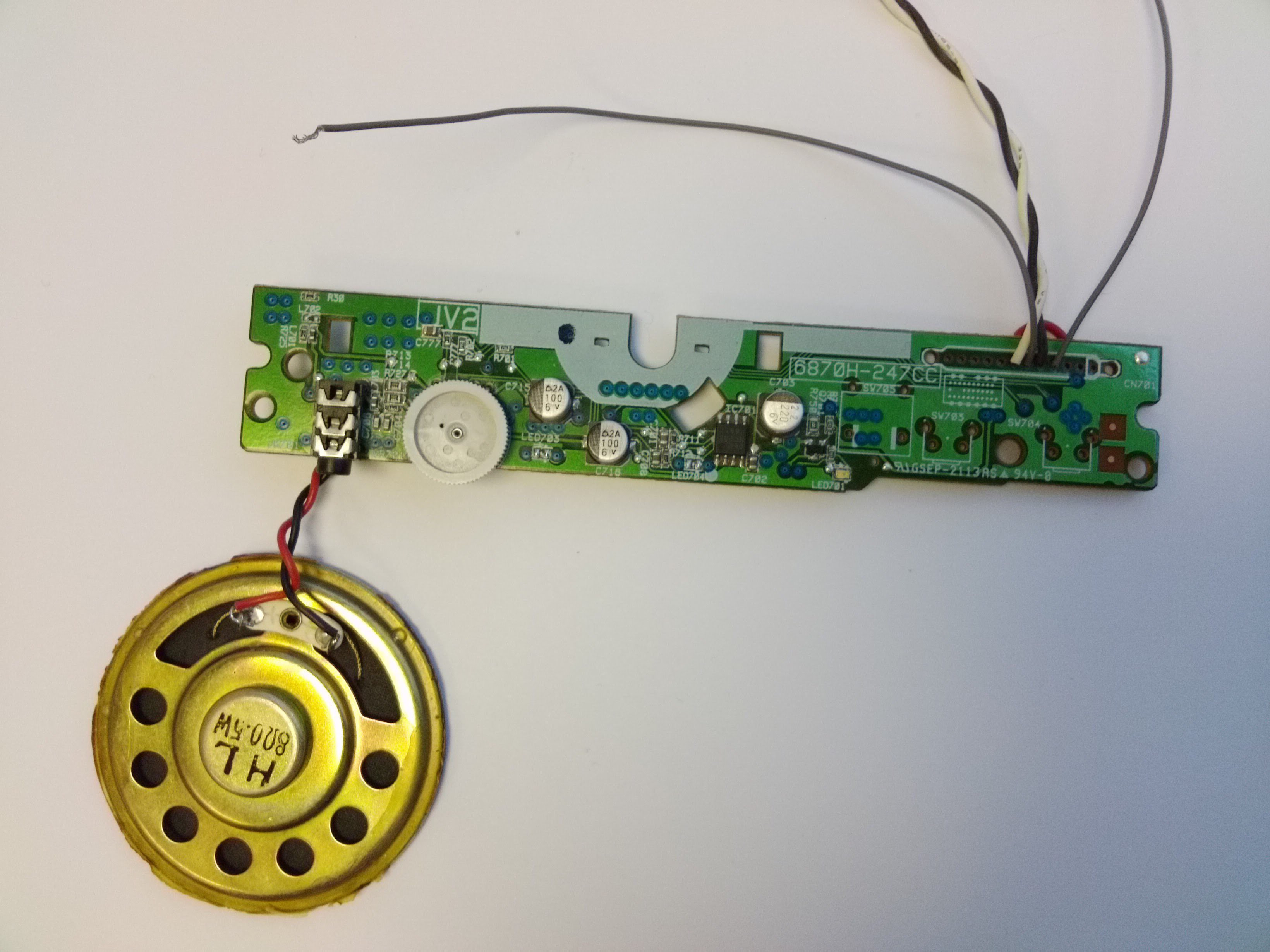
A headphone amplifier salvaged from a CD drive
The DAC circuit described earlier is not designed to supply enough current to produce a decent volume through a speaker, therefore an amplifier is needed. Once more, given that my performance expectations were quite low, I could have made a simple A class amplifier. However, I had some old CD drives laying around, some with headphone output which indicate they had an amplifier ready to be used. Headphone amplifiers from scrapped CD drives are a classic, they are often found in a separate PCB that contains the LEDs and the push buttons of the frontal panel of the drive. Their use has been described before (e.g. see this Instructable). My CD drive had an amplifier IC labelled "JRC 2169 2013H". I couldn't find the datasheet but I soon realised it has an identical pinout to the APA3541 in the Instructables above. Because I was unsure what the amplifier circuit looked like, I spent some time checking the traces in the PCB of the CD drive and got the following:
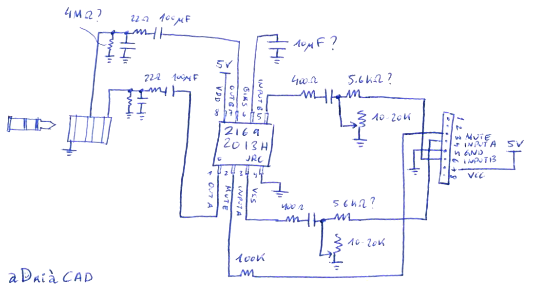
I removed the unused stuff in the PCB and left only the bare essentials I needed (including a potentiometer that allows me to tune the output volume). I wired a speaker from some old headphones and ended up with this:
 The input stage of the amplifier circuit contains a resistor ladder to change the volume at the amplifier input followed by a capacitor in series to remove the DC offset of the input. The circuit can be fed from the output of the resistor ladder described earlier, in my first test I used the sine wave generator above to play a note of constant frequency so I could adjust the volume. The amplifier is stereo so I could feed two speakers if I wanted to.
An adapter board to interface a 3.3V SPI flash memory salvaged from the controller board of a CD drive to an Atmel microcontroller from an Arduino board
When I started the project, I wanted to avoid using external flash memory and I thought I'd be able to use some very clever compression method (or perhaps use a mod tracker) to be able to fit the music in the program memory of the Atmel microcontroller. I spent some time playing with the sampling frequency and some home-made MP3-like compression but eventually gave up and decided to find a memory chip I could use.
I found a EN25F80 8 Mbit SPI flash memory in a DVD drive and found out that was enough to store a my 86 second audio loop in plain waveform format with 8 bit per sample and 11 kHz sampling frequency (948,028 bytes). This type of memory can be easily read and written from an Arduino and the same trick can be used to read and write them from a computer (see this).
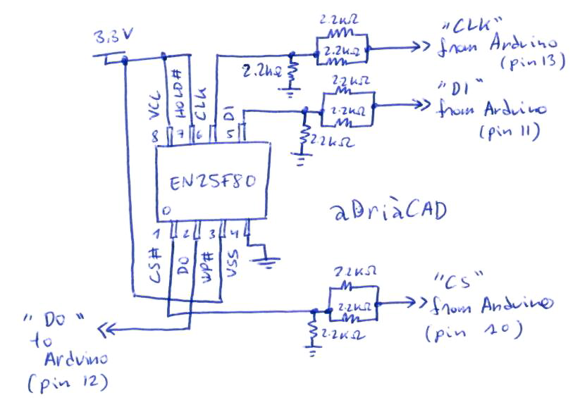
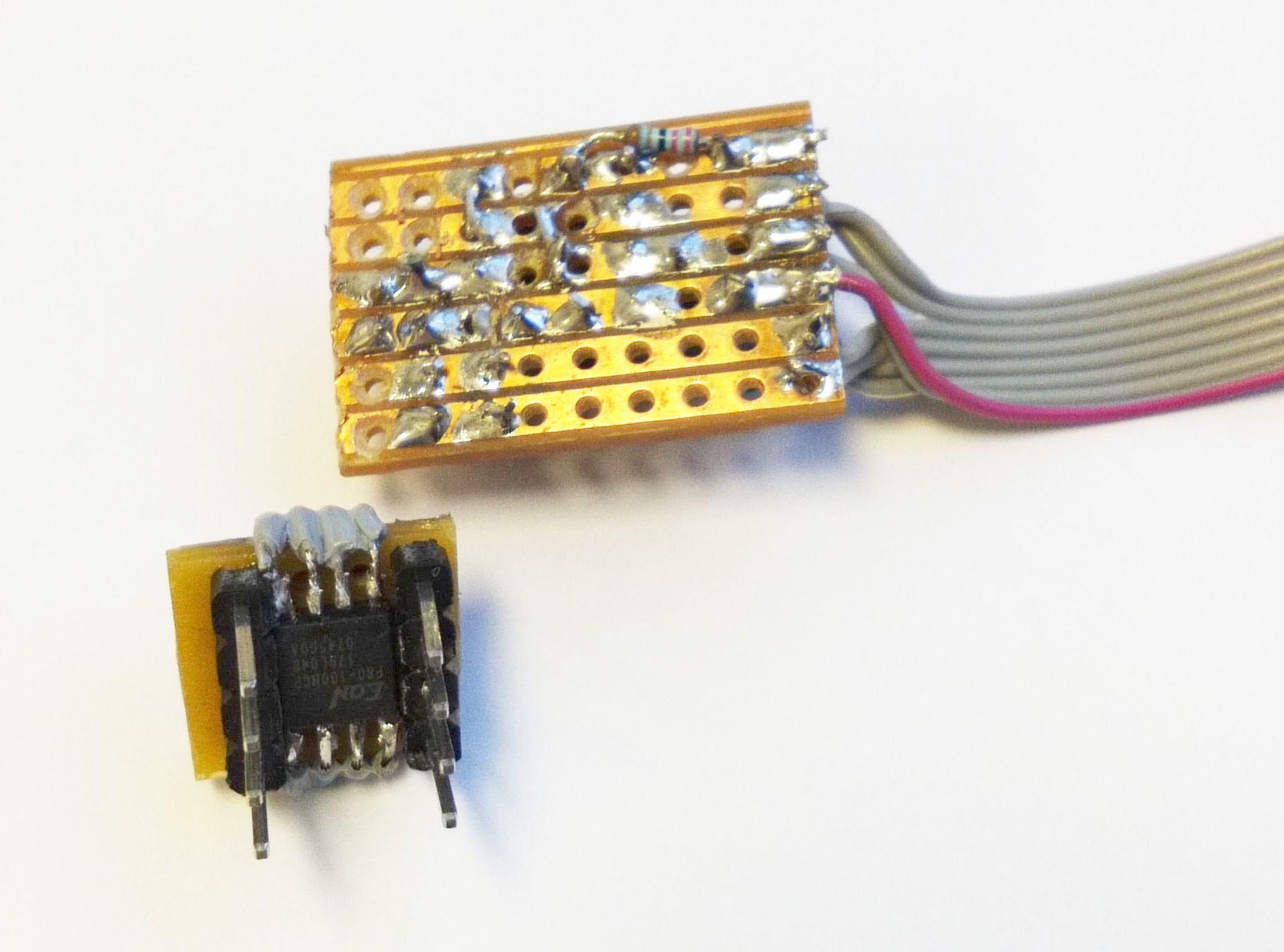
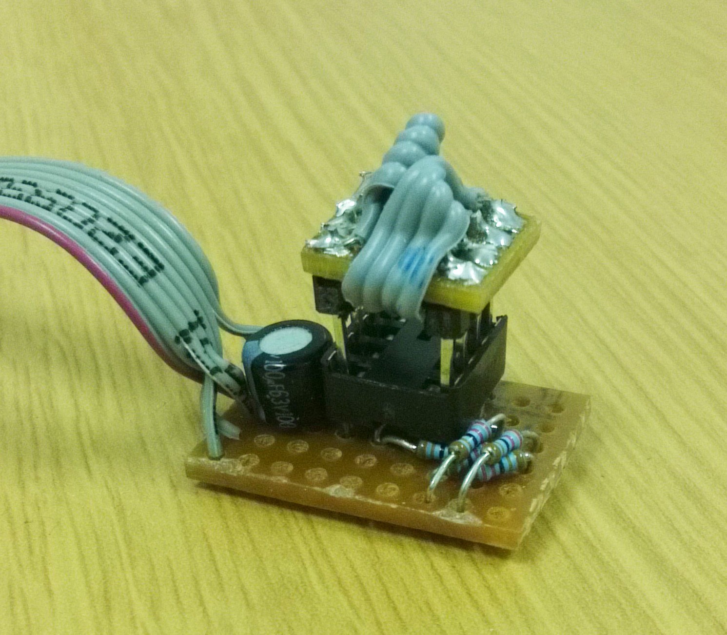
The only problem is that voltage levels have to be adapted from 3.3 V to 5 V. 3.3 V is already available in most Arduino boards and can be used to supply the flash memory, otherwise a simple voltage regulator (or even two diodes in series) can be used instead. Interfacing the digital signals of the SPI bus between the Arduino and the memory chip can be done using a common level shifter IC. However, I chose to do it the poor man's way: I used a simple voltage divider to drop the 5 V of the output pins of the Arduino to two thirds, and connected the 3.3 V data output of the flash memory straight to the Arduino, which hopefully is high enough for the microcontroller to take binary ones as ones rather than zeros. The circuit looks like this:
See from the bottom:
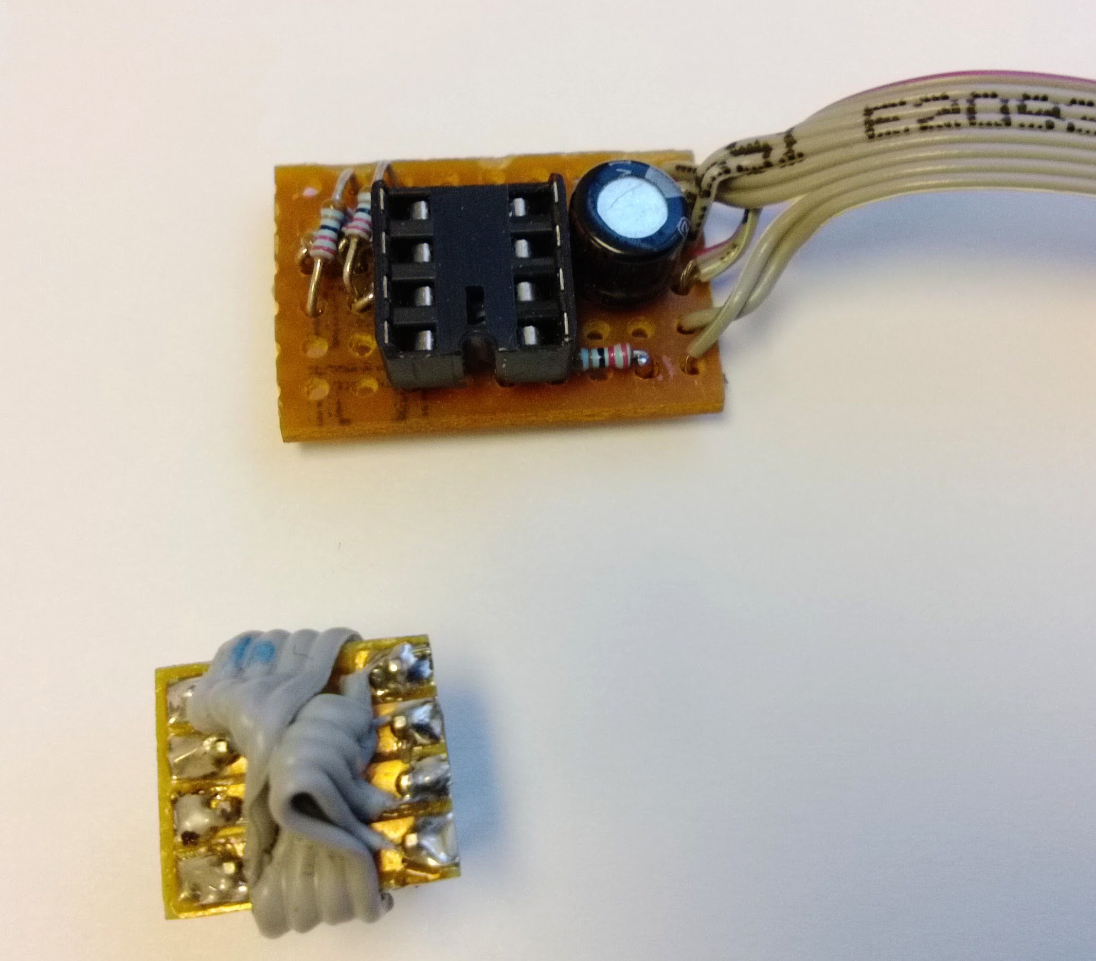 And here's a picture of the whole thing assembled:
As I mentioned earlier, reading and writing from the flash memory is straightforward. The code the enabled me to read a sample from the SPI memory and play it through the 8 bit DAC can be found in Pastebin, the code is based on the SPIEEPROM example from Arduino.