 Nigel
NigelThe first set of inputs we'll be going over is Analog In. Currently I'm aiming to have 8 total analog inputs available to the user, split over two ADCs.
I've done some quick research on what kind of signalling analog automotive sensors normally operate off of and it seems that most operate on <5V. This is nice as it makes interfacing with most ADCs painless. There is however, one "high" voltage source that we'll want to measure, battery voltage. To ensure we can safely measure this, whichever input we assign to battery sensing must be able to survive voltages up to (and possibly higher than) 15V.
Automotive 12V rails are notoriously noisy so in order to get good readings we'll have to employ some sort of filtering or averaging. Let's look at what other sorts of waveforms we can expect to encounter when reading sensors.
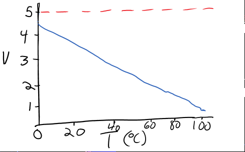
Temperature:
It looks like most automotive temperature sensors are pretty simple. The main T to V function is linear with two special cases denoting a short or open fault. Noted with 0V and 5V respectively.
O2 Levels:
O2 sensors come in two flavours, narrow-band and wide-band. As far as I understand it, narrow-band O2 sensors are the most common type used in OEM applications. They have an interesting property where there is an abrupt change in voltage at the level corresponding to a stoichiometrically balanced air fuel ratio (AFR).
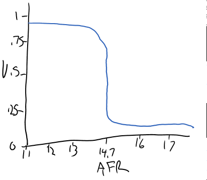
Due to the abrupt change in voltage, O2 sensors cannot reliably read the ratio beyond a narrow range of values.
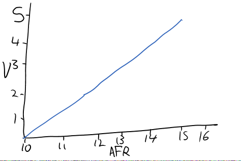
In aftermarket applications where a greater ability to read specific values is desired a wide-band O2 sensor is used. These sensors are usually linear over a wide range of possible AFRs.
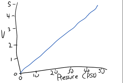
Boost/Pressure:
Pressure sensors are also linear. There a few different types spanning different usages. A coolant pressure sensor we'd expect never to have a value below 0 PSI(gauge) however, a boost sensor for a turbo setup would expect to see negative and positive gauge pressures. The details in how these types of sensors map pressure to voltage will need to be studied more in order for us to implement a wide variety of pressure sensors.
For pretty much every type of sensor we'll be able to read the output without any sort of scaling. This is nice as it'll bring down the board complexity by a fair amount. In the case of the battery voltage we'll have to convert it down into the range that our ADCs can read. We also need to keep in mind that automotive power rails are extremely noisy and can have some pretty extreme anomalies. I can't remember the name, but there's a standards document that outlines the kinds of waveforms that we need to protect against. I'll try to find it and include some of the recommendations in another project log.
In my next log I'll go over the actual ADCs as well as plan out how I'm going to replicate these signals.
Discussions
Become a Hackaday.io Member
Create an account to leave a comment. Already have an account? Log In.