Dave Gönner
-
D-type Flip-Flops
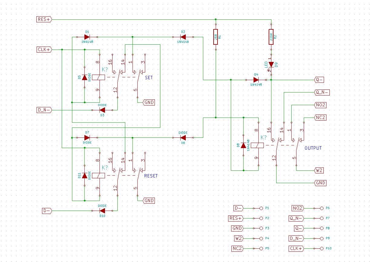
12/07/2015 at 13:18 • 11 commentsThe Johnson counters in the clock are made by stringing together individual flip-flops. This design uses D-type flip-flops. As I wrote before, the design of these flip-flops is copied from Simon Winder's design. He does an excellent job at explaining how they work in the following video.
I took Simon's schematic, modified it slightly to suit my needs and then made a circuit board layout in KiCad. All the 15 flip flops in the clock are exactly the same. Here is the schematic:
![]()
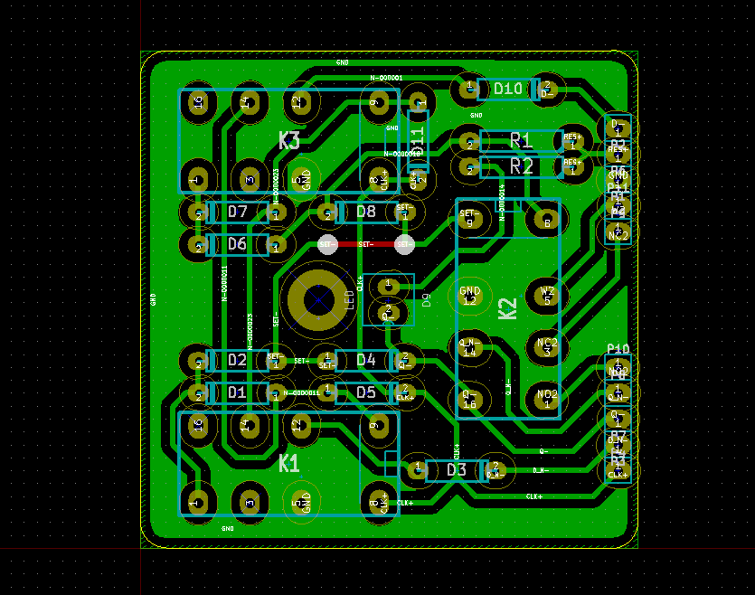
I ordered the cheapest 5 volts relays I could find off of Ebay. Their size is the main determining factor in the circuit layout of the flip-flops. After many revisions, this is the final board I settled on:
![]()
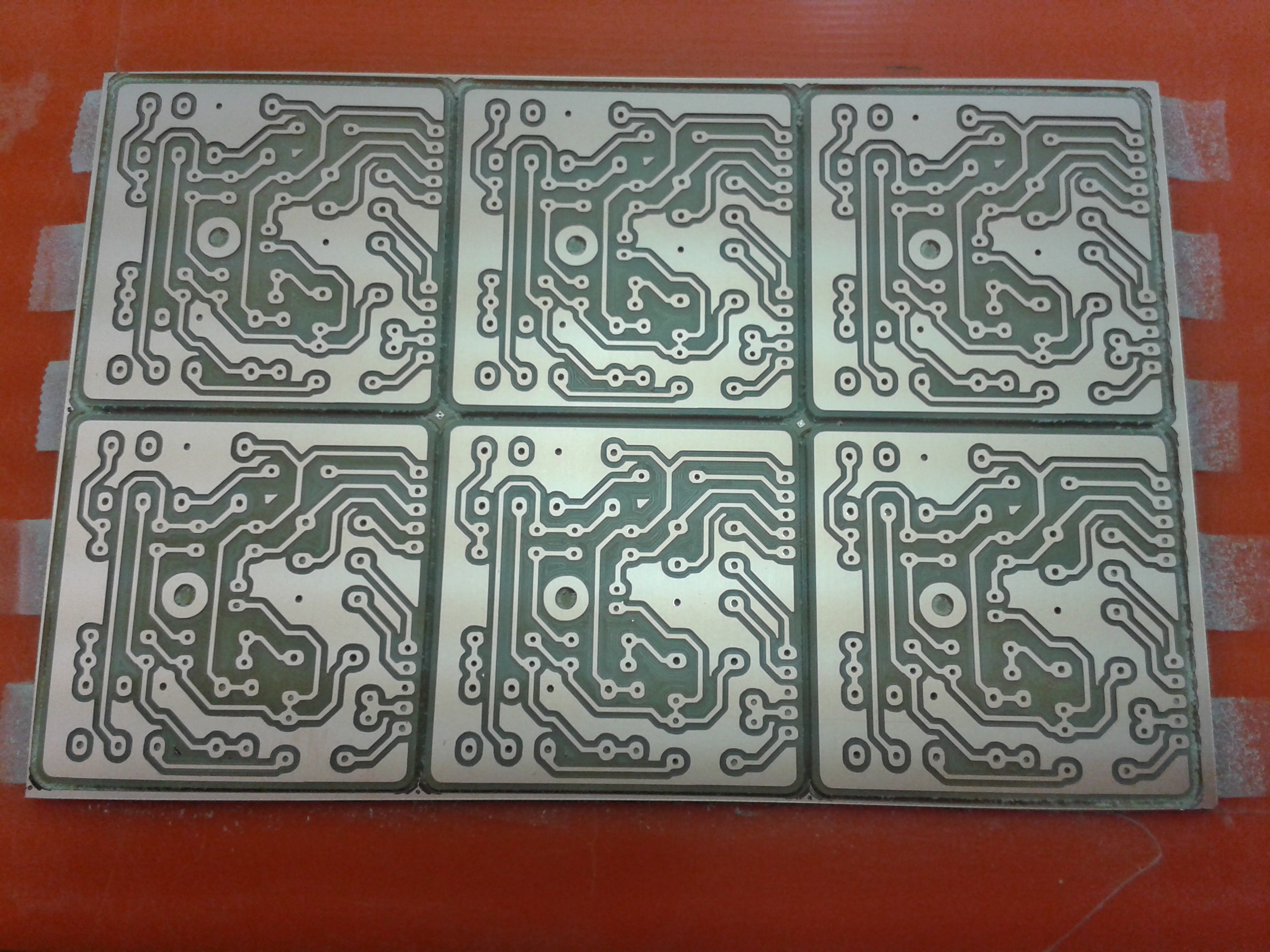
After lay out the circuit board, I milled the pcbs out of single sided FR-1 stock using a Roland Modela mdx-20. I want to thank Fablab Amsterdam for the many hours of machine time. I only have 160x100 circuit board blanks, so when laying out this board (and all the others in this project), I had to keep the size down and fit as many on a board as I could. Here's the result after milling six of them in one go:
![]()
-
Overview
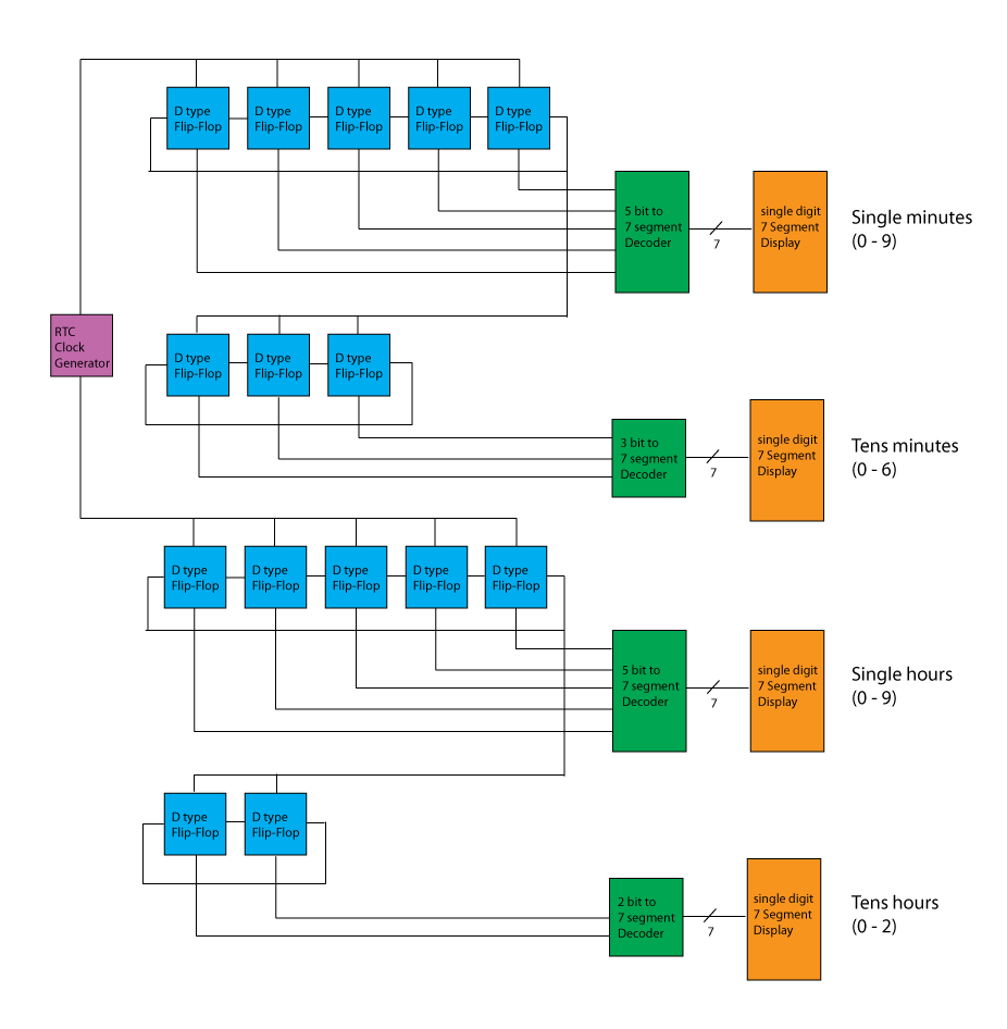
12/07/2015 at 11:48 • 0 commentsSchematically the clock consists of four Johnson counters, cascaded together to count and display time in 24hour format. I chose Johnson counters instead of regular binary counters because the decoding to seven segment requires less logic gates than a regular binary counter. Every logic operation is done with relays, so every operation counts.
A Johnson counter has 2n states, so a 5-stage Johnson counter can have 10 different states. Minutes count from 0 to 59. The lower digit goes from 0 to 9 and thus requires a 5-stage Johnson counter. The upper digit goes from 0 - 5 and therefore has only a 3-stage counter. The same logic applies to the hour counting.
This is a block diagram of the different functional blocks in the clock.
![]()
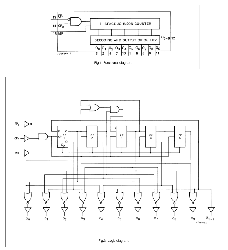
The design of the counters and the decoding circuitry closely resembles what can be found in a 4017 chip. The following was taken from a datasheet. Minus the two AND and OR gates at the top it is the same. After decoding from 5 bit to 1 in 10, it is further decoded to 7 segment via an array of diodes (not shown here).
![]()
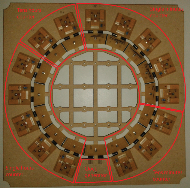
This is a front view of the partially completed clock and shows the layout of the different functional blocks. The four decoders and seven segment displays are not yet mounted in this picture. The MDF board is just a temporary frame to hold the parts for assembly and soldering. Once everything is finished, it will be transfered to a 6mm clear Plexiglass sheet with only the holes for the screws drilled. The large cutouts in the MDF are for easy access on the back for soldering and will not be present in the final Plexiglass sheet.
![]()
Relay Logic Clock
A digital 24 hour clock using only relays and diodes for the counting logic.