 Vittorio Loschiavo
In the following video you can see the snowplow robot in action, somebody told me that seems that for shoveling the snowplow robot must take the run-up, IT IS NOT SO, I have made the video to show how the snow get removed.
How it is made?
The robot is made up of a frame that supports a motorized blade (that can be raised and moved) and the traction system composed of electric motors, wheels and caterpillars tracks.
The chassis is realized with rectangular section iron bars welded together. The size of robot is 600X375X240 mm, excluding the blade, and its weight is about 30 kg.
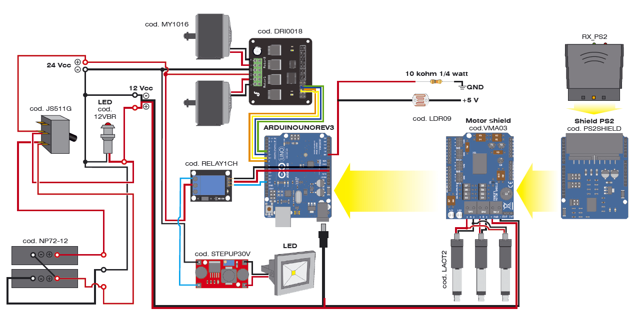

Electrical and electronic part of the snowplow is based on Arduino Uno, hosting three shields and interfacing with:
- MOTOR DRIVER
- RELAY BOARD CHANNEL
- DC/DC converter step up
The shield mounted on Arduino are the motor shield to control the three linear motors that manage the movement of the blade and the PS2SHIELD, which allows you to interface with the PlayStation 2 (PS2); the latter requires the RX-PS2, which is a 2.4 GHz radio receiver for sending/receiving specific commands from the aforementioned console. The wiring diagram of the robot is what you find in these pages; the power source is made by a series of two lead gel batteries by 7.2 Ah: we take the 12 V from the mid-point connection of the two, while between the negative and the positive of the series we take 24 volts. A switch (125V, 2×15 ampere) controls the two supply lines. With 12 volts, we run Arduino, which will power the shields through its pin-strip; a LED (internally mounting the limiting resistor) will indicate when Arduino is running.
The 12 volt directly from the battery stack is also feeding the power section of the motor shield. In fact, since the absorption of the three linear actuators (cod. LACT2) is high, it is not advisable to take the 12 V from Arduino: you opt for the external power supply to be provided to the appropriate PWR terminal. To use the external power supply, you must move the jumper (on the shield) near the terminal, between the central and the EXT. The management of the shield requires a special library for Arduino, supplied with the component. Each linear actuator is composed by a 12 Vdc gear motor using a worm screw to move a shaft back and forth along its length (maximum excursion of 5 cm).
The actuator has a dynamic load of 50 kg and a maximum speed of 1.3 cm / s. It is able to support up to about 250 kg, when not moving, and the torque ensures the maintenance of the position of the shaft even in the absence of power. Two limit switches provide the engine to stop when it reaches the maximum extension and contraction, while the diodes allow reverse direction after reaching the limit point. The actuator is made of metal and is sealed to protect it from dust and water (IP63 rated).
Let us now turn to the 24 volts supply line, which is feeding the power part of the snowplow, which are the traction and the projector (optional) sections: the first is based on the motor driver, to be connected with four wires to the same number of Arduino digital lines. The motor driver is a double bridge power driver capable of driving two brushed motors continuously with a voltage of max 35 VDC and a current of 15 A (each).
By interfacing with Arduino and using only four digital I / O (2 PWM), you can choose the rotation direction and speed of the motors. The circuit has four control pins, four LEDs that indicate the rotation direction of motors, two pins for the board power supply (5 Vdc) and two aluminum heat sinks located in the rear of the printed circuit, necessary to dissipate the heat generated during operation at full power.
For the management of the driver by Arduino, the manufacturer provides a special library. The output terminal blocks allow you to connect the two engines, to be connected as indicated by the diagram (do not invert polarity, otherwise the...
Read more »


 MrDreamBot
 dekuNukem
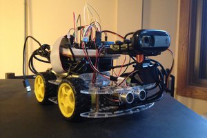
 Coleman D
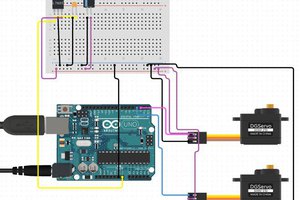
 hIOTron
How is the PS joystick connected to the controller?