Close
0%
0%

D.I.M.E.R PROJECT 6 DOF Robot Arm

This is my robot arm, with recycled materials, can pick 2 Kg and costs around 100$

Similar projects worth following
This is a robotic arm that i'm building with recycled materials, it has 6 degrees of fredoom. Expectacular low price (around 100$). payload of 2 Kg with 115 cm lenght.

It's controlled with Arduino, and has manual and automatic control so it can be used for pick and place, palletizer or whatever you want.

I've just closed this project because i want to do another one, bigger, stronger, more precise and totally replicable so that anyone can build it. You can see the project here: https://goo.gl/uVzI0Q

I hope you enjoy it and of course if you need more info, contact me.

Twitter @antonioregueira

website:

Spanish www.dimerblog.wordpress.com
English version www.dimerblog2.wordpress.com
github https://github.com

Hi!

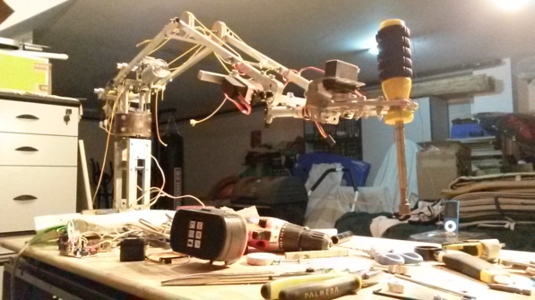
I'm developing this project as a challenge, because i saw a lot of robotic arms but with very high prices (for some applications you don't need an accuracy of 0.5mm). So i think that it could be made of recycled materials and some 3d printed parts. Now I'm testing a lot of configurations to do the best job.

My first goal is to have an accuracy of 5mm. i know that it's too much but it's only the beggining.

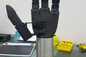
Second is to add another degree of freedom at the claw.

Third is to add some kind of artificial vision.

Fourth is to have a multitool system, so you can work with a screw or a soldering iron, a drill etc

Last is to standar electric windows motors so you don't need to adapt 3d printed parts to your motors. But if you want to use different motors and need help, contact me :)

Of course i'm trying to use usual things that you can find near home.

I will post any changes, i hope you like it and, of course, if you need more information, don't hesitate of asking me by mail, twitter or my website.

See you soon!!

Here's the last video i did. (11-12-2016)

iam - 1.31 MB - 08/20/2016 at 02:08

Download

iam - 568.50 kB - 08/20/2016 at 02:08

Download

ipt - 412.00 kB - 08/20/2016 at 02:07

Download

ipt - 144.00 kB - 08/20/2016 at 02:07

Download

ipt - 130.00 kB - 08/20/2016 at 02:07

Download

View all 19 files

  • 1 × Bicycle fork
  • 4 × square aluminum profiles 12x10 and 10x10
  • 2 × Electric window motors
  • 1 × gt2 belt
  • 3 × Servos MG995

View all 13 components

  • Project finished

    Antonio Regueira12/11/2016 at 22:50 0 comments

    Hello!

    This is it. The last entry I will make on the D.I.M.E.R mk1 project. A couple of weeks ago I started thinking about the design of the second version, at the moment mk2, more powerful, bigger, more precise and totally replicable so that anyone can build it. As soon as i design something i will publish it here.

    I dont want to closed this project without uploading some videos, in the first one i programmed some movements, the second is from another perspective and the third is about the detail of the gears, I hope you like them.

    See you soon!

  • New Assembly

    Antonio Regueira11/07/2016 at 22:43 0 comments

    Hi everyone!

    In the last post commented on a new assembly for the elbow, I had to make a couple of adjustments but it works well.

    To make the movement I had thought of gt2 belts, but when I had the assembly finished, making tests of efforts, I had to tighten the belt so much that it broke, so I chose to use special strings that yield nothing.

    In the shoulder gear system, I modified the wheel where the aluminum profiles are hooked, so the shoulder can rise by 230º, improving the range and maneuverability. I also had to place a series of plates to join the 3 axles of the gear train so that in no case they can be released.

    Finally I modified the whole wrist, now uses a semi-differential system so that, with only two DC motors, I can rotate as well as up and down, this design I owe it to the project Thor, by the maker Angel Larrañaga. Motors are recycled from an office printer, these have a speed of 2 RPM, because of this I made a multiplier of 3.5 so that they moved a little faster, as the gears are made in plastic it couldn't hold the weight of 2 KG so i put Inside an aluminum shaft of 10x10 and, inside of this, an 8 mm shaft of steel

    As always, new built, new video, here the last one.

    Enjoy it, see you soon!

  • More power and accuracy

    Antonio Regueira08/20/2016 at 00:52 0 comments

    Hey everyone!

    I've been working with gears and designing new ways of movement.

    First of all i added another motor to the shoulder movement, so now, there are 2 identical motors moving this part.

    Second, i changed the motor of the elbow, now there are 2 motor of old drills and, with a worm gear and a belt it's moves perfectly.

    i couldn't make this real because i stayed without PLA and i couldn't print all the parts but i have photos of some parts and the entire design in CAD.

    One important fact is that i tested the new assembly of the shoulder and i can pick up 2 KG at 2,5 meters of distance, that it's a lot of efforts and the gears work fine :) you can see this test before the pictures.

    Because of this, i improved the movement of the shoulder and now it can rotate 330 degrees at this axis.

    Probably in 1 or 2 weeks i will print this new assembly and make a video working and moving.

    I reccomend seeing all the following pictures and if you have any question or comments please, let me know ;)

    I upload this entire CAD file so you can download.

    See you soon!


  • Gears

    Antonio Regueira07/03/2016 at 09:24 0 comments

    Hi everyone!

    In the previous post i improved accuracy addi20160703_102539
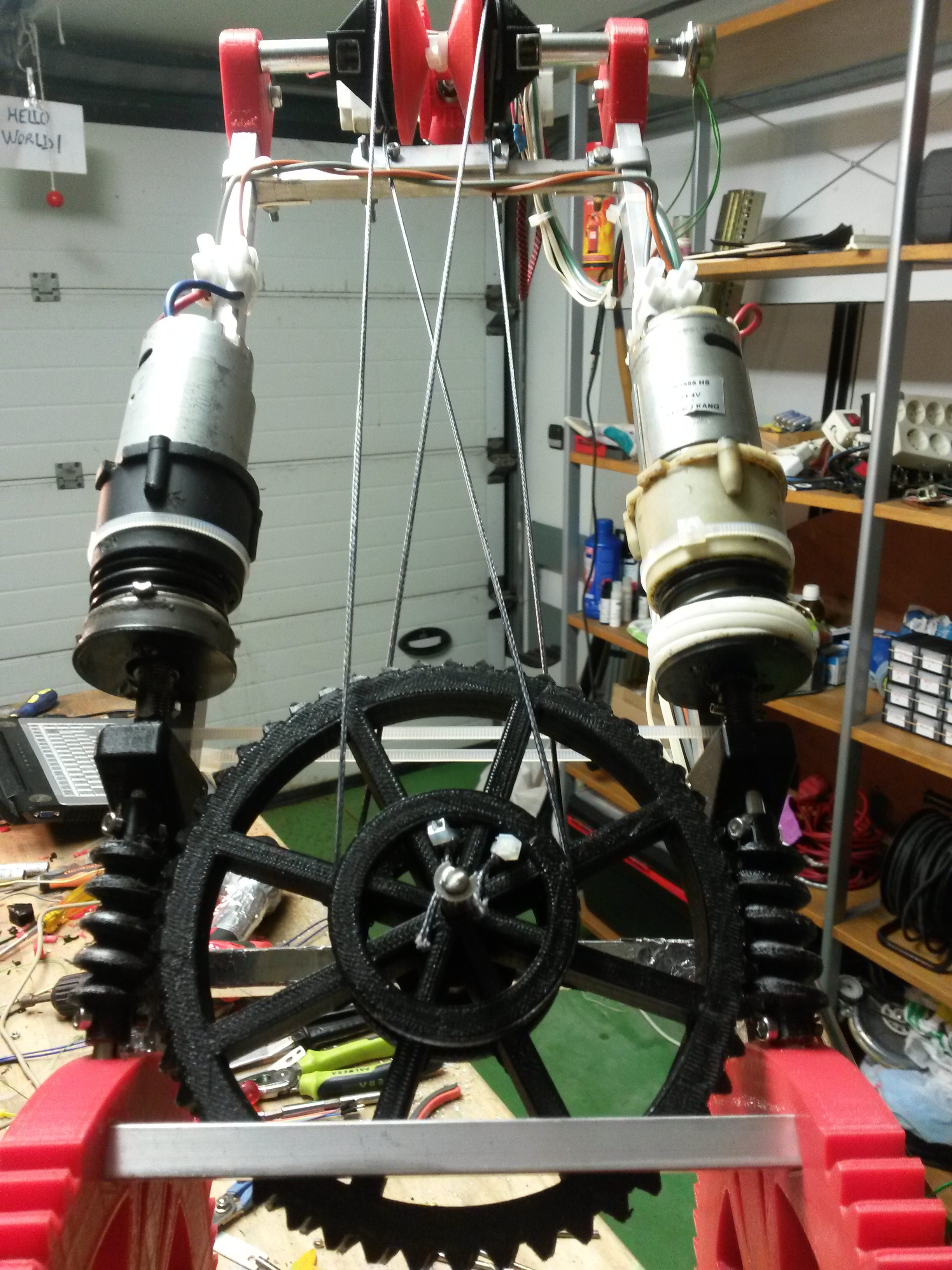
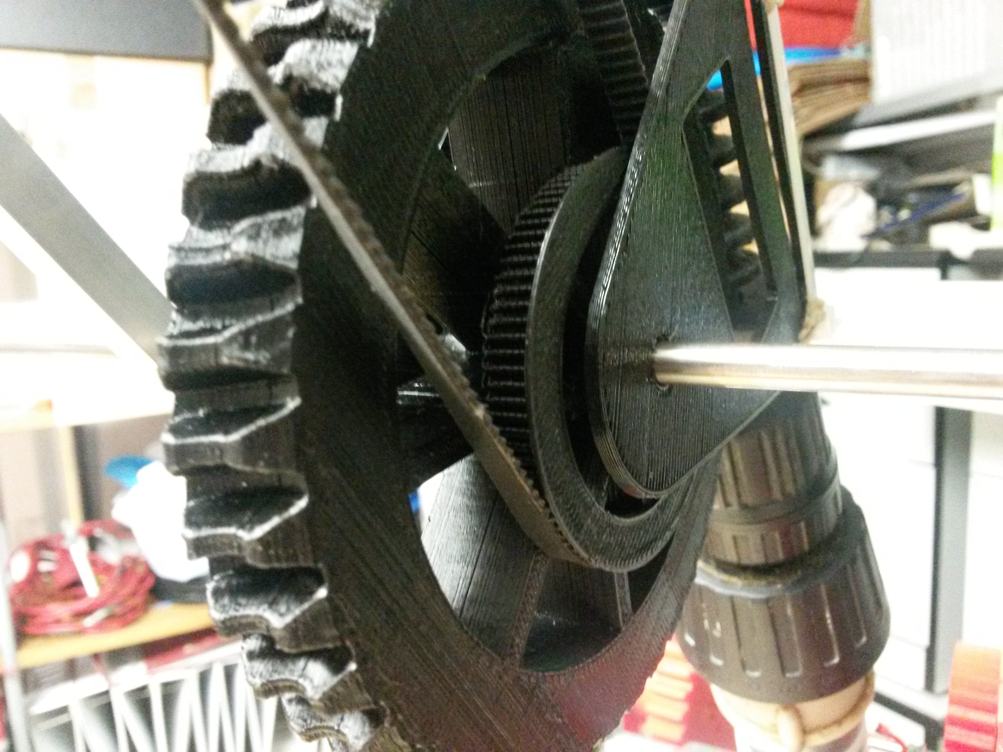
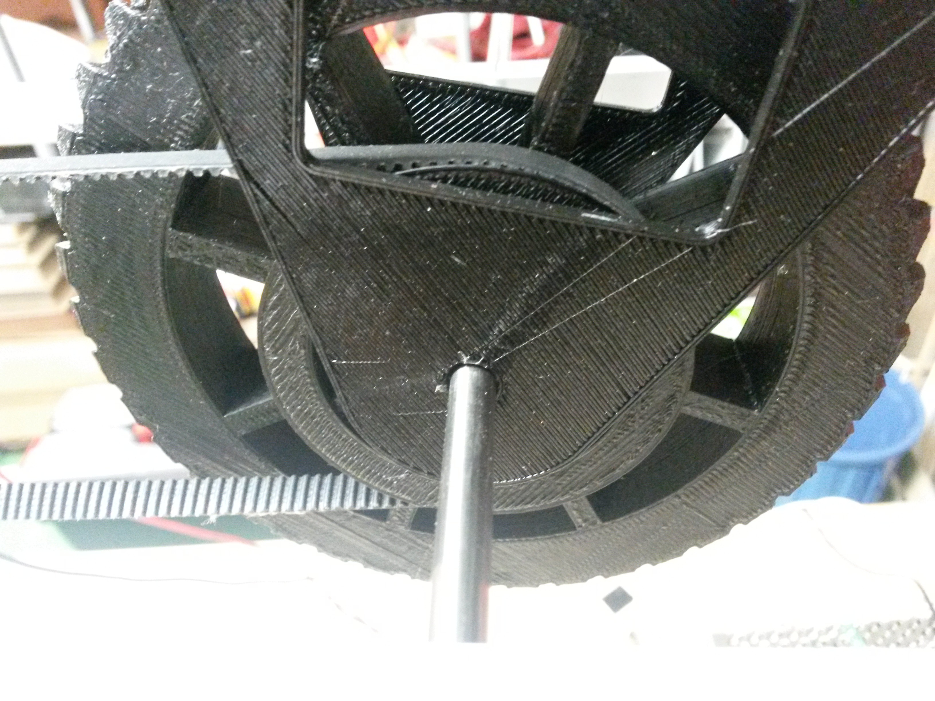
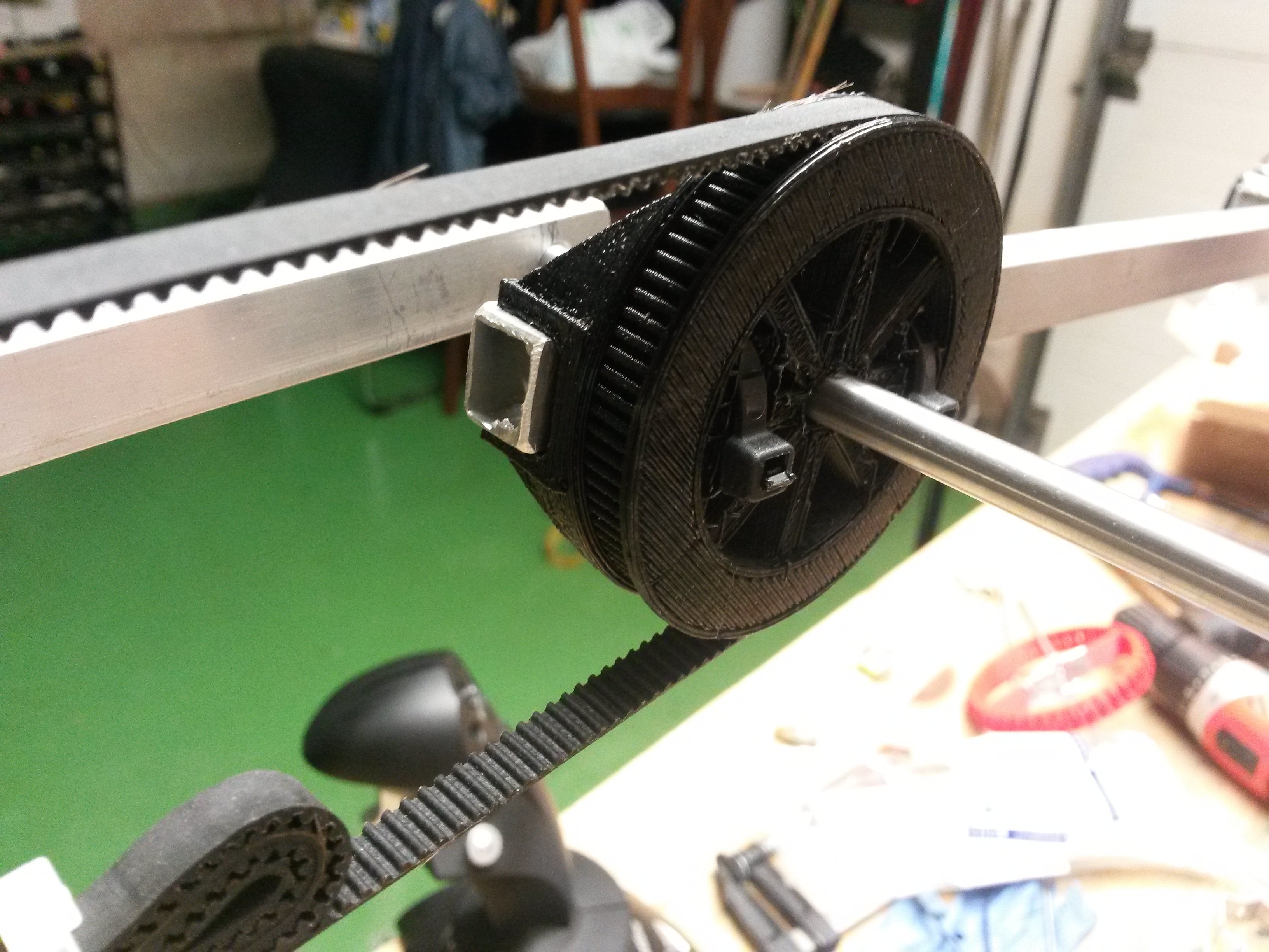
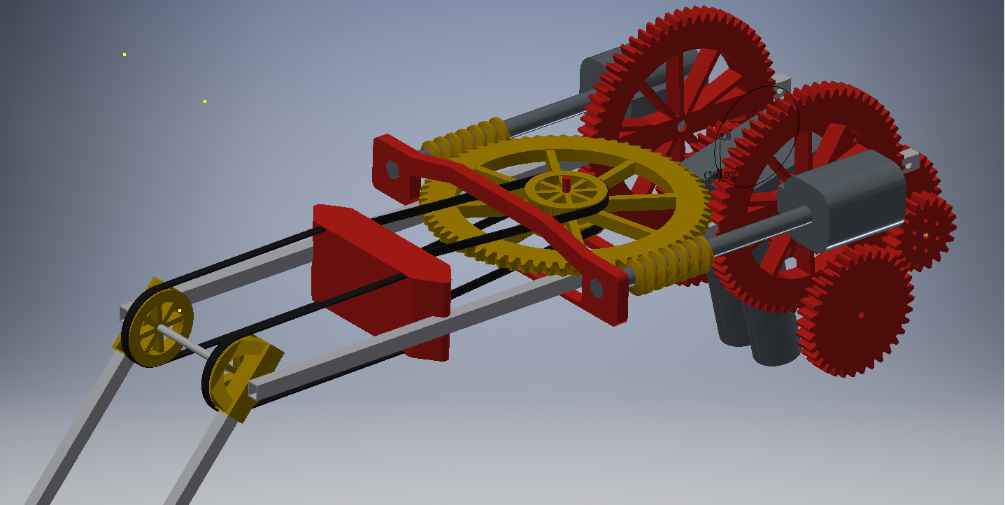
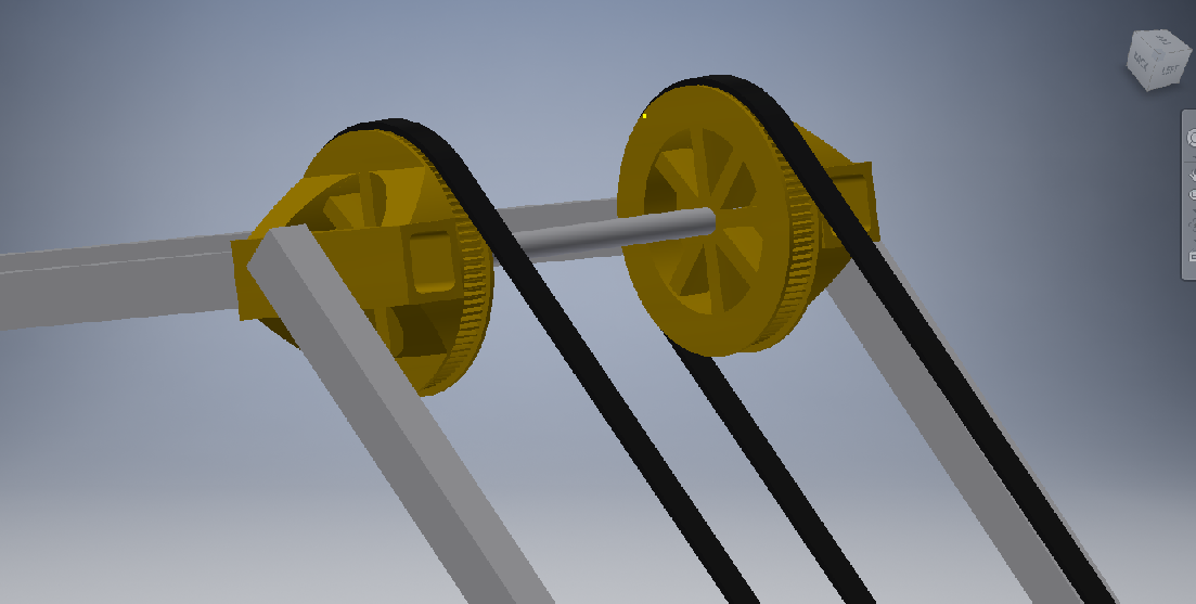
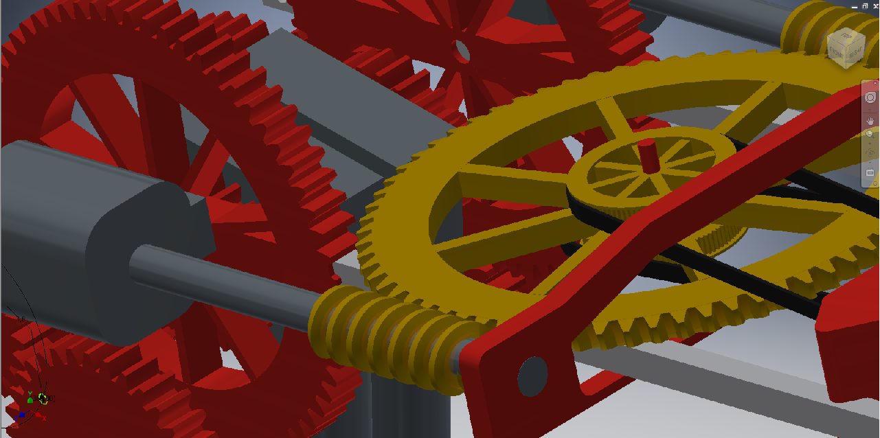
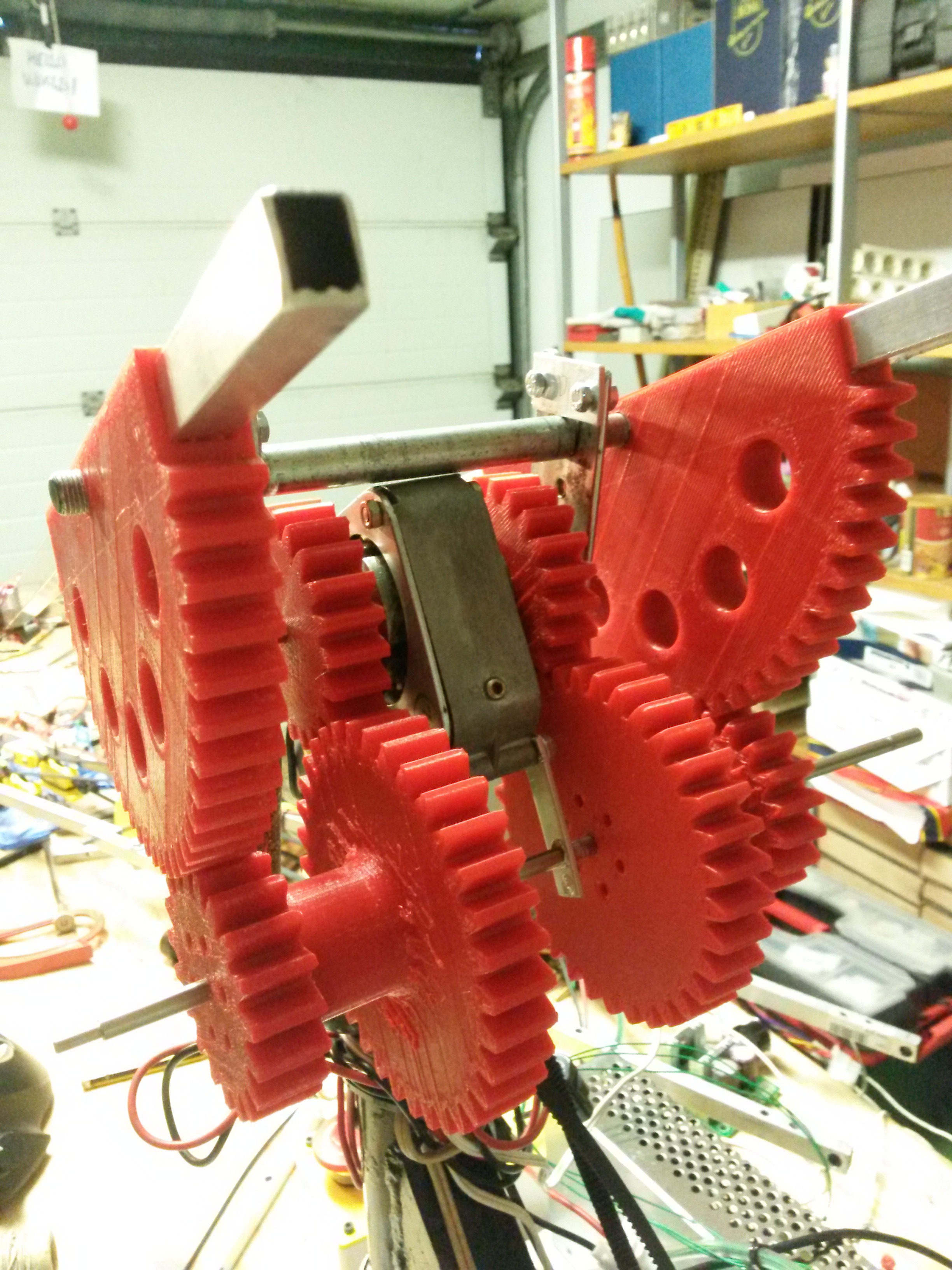
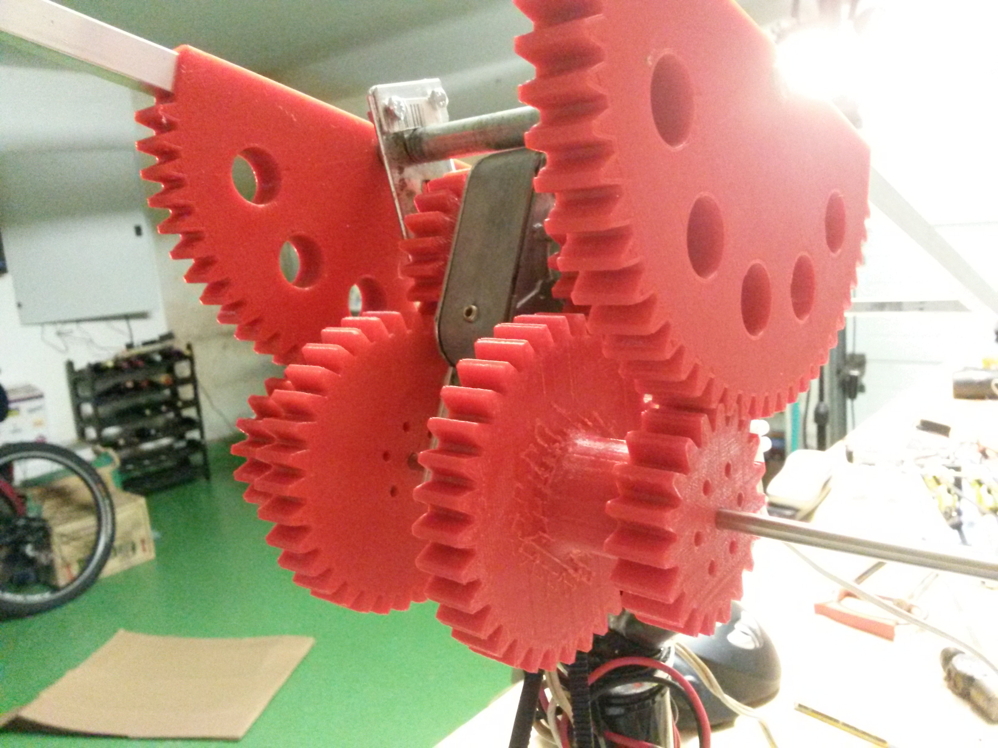
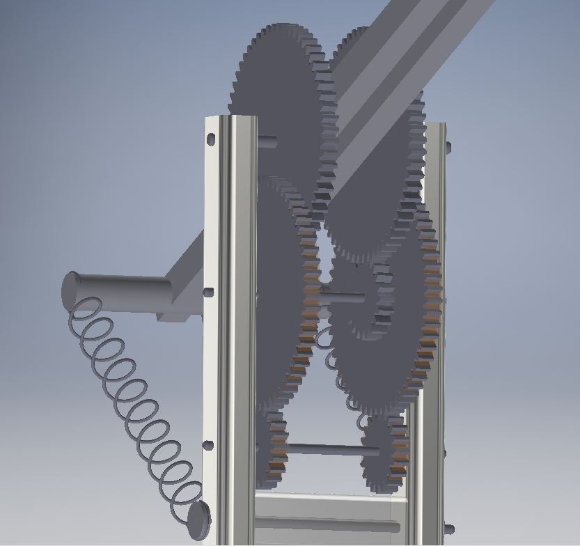
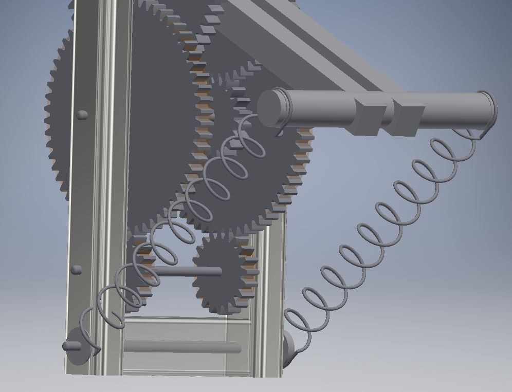
ng a belt to the shoulder and it worked fine, but this way I couldn't apply force to both direcctions, so I decided to make a printed gears.

    After design and some quick calculation this is the result. In fact this new assembly make posible that the arm can be dismounted by removing the two pieces that are above the axis to transport it easier.

    Here's a video of how they work:

    Now I'm thinking about how to add a spring to help to lift the arm, it would be something like the following image.

    See you soon!

    DIMER4

  • Improving efficiency

    Antonio Regueira05/28/2016 at 22:07 0 comments

    Hi everyone, last weeks i thought about improving accuracy on the arm, one friend told me about putting springs so i read about this and it's a very good idea, putting some springs, motors needn't to work so hard, and can pick up more weight. i tried to make some skeches. It's only an idea and not the final result. what do you think about this? the motor would connect with the lowest gears with a gear ratio of 1/9.

    And with this gears i can make force in both of direction, not only elevating.

    I uploaded the file to my repository if you want it.

    See you soon!

  • more precision on the wrist and the claw

    Antonio Regueira04/26/2016 at 23:38 0 comments

    Now that the shoulder has more precision i need to improve the wrist and the claw, Because i saw that when i did some fast movements it quake a lot.

    By other hand i need to do a software where velocity increase and decrease so movements will be more fluid

  • Improve accuracy

    Antonio Regueira04/23/2016 at 17:20 0 comments

    On previous video you can see that the accuracy is very poor, so i'm working now on it.

    I think that the problems is the shoulder (becasue i use ropes to transmit motion).

    I need to change it to gt belt and improve the movement of the motor shaft.

    [25-4-16] i changed ropes to belts and added a new spindle. you can see the explain at the instructions.

  • Programmed movements

    Antonio Regueira04/23/2016 at 16:09 0 comments

    Now i need to program movements to do repetitive movements, i made this at march 2th

  • Move

    Antonio Regueira04/23/2016 at 16:05 0 comments

    First log was to move all axis, i made this at november 7th

View all 9 project logs

  • 1
    Step 1

    Vertical Axis

    20141116_012535
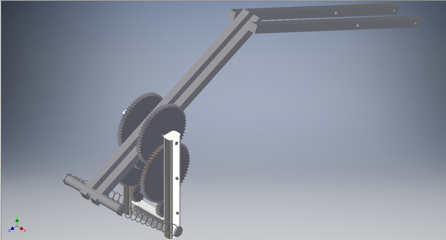
I used a base to anchor legs of a garden arbor and cut one aluminum profile 20 x 20 mm 1 meter long into 4 sections. I screwed these sections to the base and attach to a table, which in theory would be provisional.

    I dismounted an old engine that was not working and took the housing, the two caps and the shaft (heating it with a torch you can take it out easily). As seen in the photos had to cut with the angle grinder to adjust one dish at 4 profiles had placed previously.

    20150131_152651I took a steel plate, gave U-shaped and placed on top of the 4 aluminum bars looking down, so the first part of the vertical axis was ready.

    The second shaft portion beginning with the other motor plate and the housing, cutting four aluminum profiles 10 x 10 mm length of 15cm and placing them inside the cylinder. to have much more resistance I put two X-shaped pillas at the base, making it tight.

    At the end of this vertical axis i cut and placed another sheet steel, for attachment to pillars I used a Meccano brackets.

  • 2
    Step 2

    Joints

    The arm is already taking shape, now the joints. I installed 3 joints, one of those is the wrist that need an entire post.20141214_204508

    At first I thought of making a telescopic extension. The idea was a square profile with a nut anchored go through a cylindrical profile. A threaded rod would rotate to move the square profile.

    This system easily solved several problems but getting engines that could move the bar quickly was almost impossible, so I switched to a 3-point joints, hereafter ‘Shoulder’, ‘Elbow’ and ‘wrist’.20150208_215339

    The profiles are rectangular aluminum of 12 x 10 mm.

    Now that were already in place came the part of the movement .Luckily, a friend had just cleaned the attic and had given me several things, including two power windows car engines. These motors are 12V DC and have the characteristic of having much torque, just what I need.20151004_005544

    The motors are hooked by aluminum frame to the structure. In the third picture the square frame(which makes motor shaft) inside cylindrical frame. It’s like a tread. This assembly is wrapped by a sheet of aluminum of 10 x 2 mm.

    To transmit the movement thought of using ropes, but only temporarily, because they have the disadvantage of stretching the load weight, a situation to be avoided in a system designed to be accurate. In the future they will be changed by metal chains.

    And just it left wrist, but that deserves a separate post.

  • 3
    Step 3

    Wrist

    20150922_215537
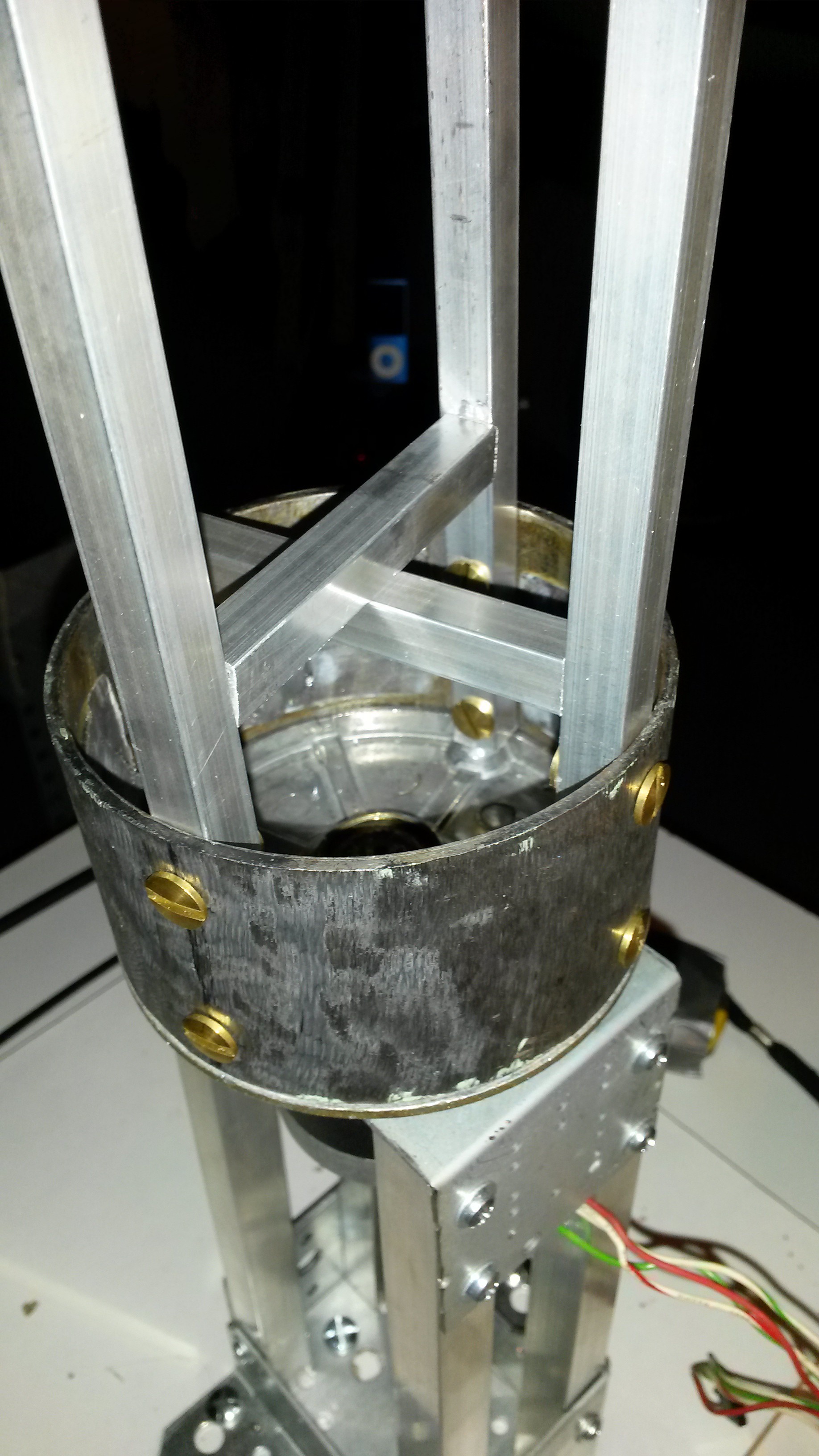
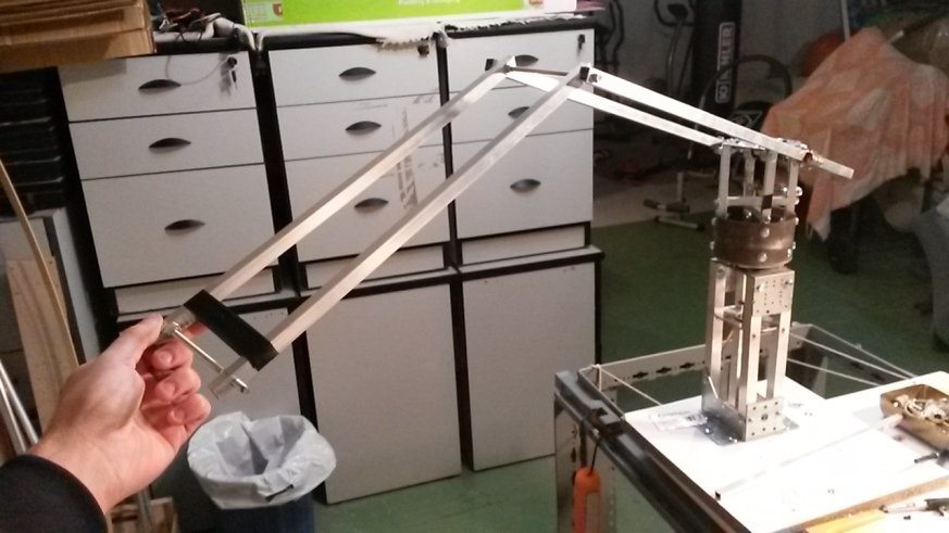
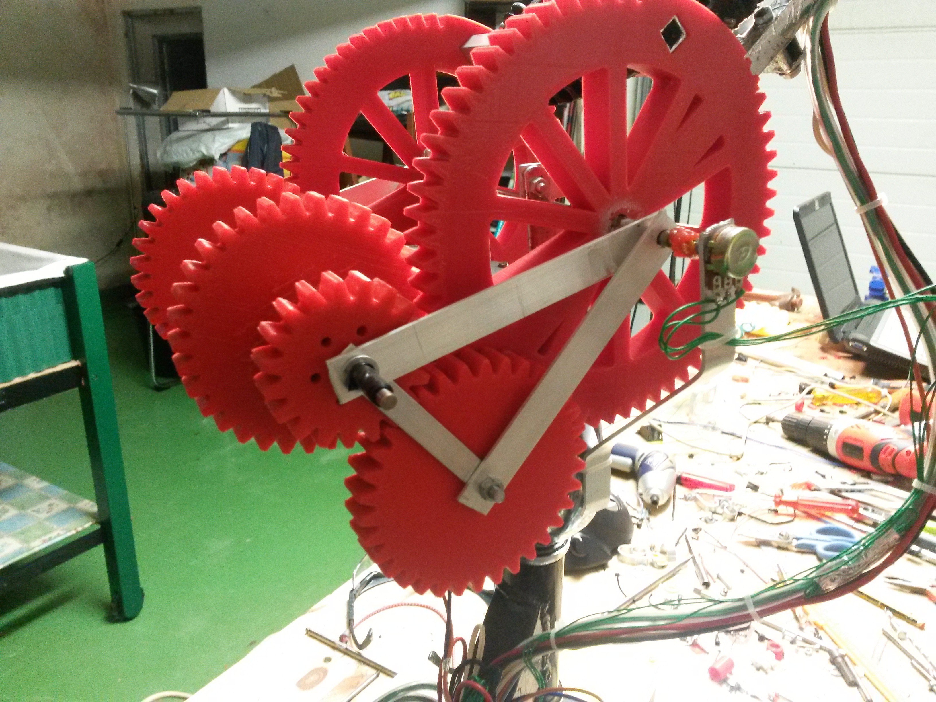
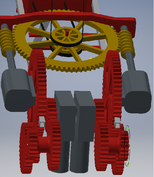
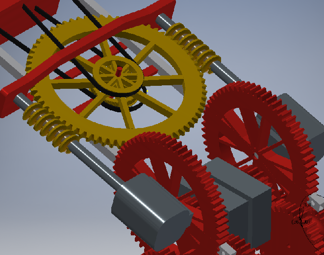
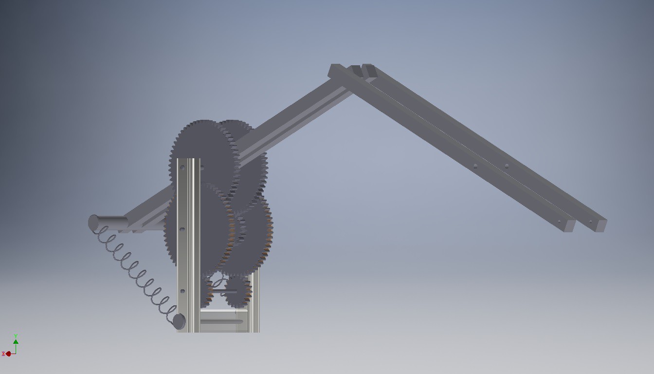
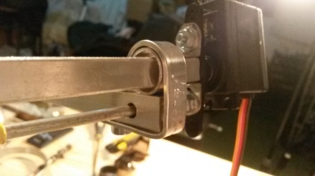
We have reached the last mechanical phase of dimmer, i will explain how I made the wrist.
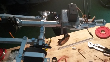
    This part took me a lot of work, since the arm had to pick up one kg but moving with precision. To do this, I designed the wrist with two axes. One of rotation and other to go up or down.20150923_162151

    I joined the clamp (bought by Internet, looking robot gripper) with a square profile of 10 x 10 millimeters. This frame will go inside of a cylindrical frame, and this frame is hold to the other frame that goes up and down.

    After this i joined the servos. For vertical movement I used two Hd 1501 MG servos, with a torque of 17 kg-cm, while I used two MG995 servos of 11 kg-cm of torque for rotation.

    Finally, I attached Hd 1501 MG servos to the structure and set the MG 995 to the cylindrical frame.

    See you soon!20151004_005557

View all 8 instructions

Enjoy this project?

Share

Discussions

Similar Projects

Does this project spark your interest?

Become a member to follow this project and never miss any updates