Close
0%
0%

VR Tracker

An OpenSource 3D position tracking system compatible with all VR headsets to make VR an exceptionnal experience

Similar projects worth following
VrTracker uses at least two infrared camera to track an infrared dot on the user headset, and computes its position in a 3D space to allow the user to move around in a virtual environment.

Oculus Rift, VR One, Samsung Gear, Sony Playstation VR… All those Virtual Reality are great, but they are missing something ! They do not have a position tracking system ! This means you can look up down right left, but can’t stand up and move around in your room. Too bad because the best experiences happens when you can actually move around by yourself in your virtual environment.

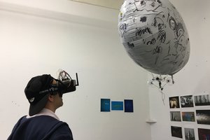
How do I know ? Well I have been working with many of those headsets as a consultant for an augmented reality company, and I have developed a 3D position tracking system compatible with all those devices ! And let me tell you, I have tested this tracking system with Samsung Gears, and the result was AWESOME !!! I was able to move around in a 5 meters by 8 meters room and therefore in my virtual environment.

functionnalities

What is so great about position tracking ? The range of applications is much wider ! You can for example create an experience in a museum where users could visit a pyramid using VR headsets in an Egyptian exposition. Or visit an appartement or a building even before it has been built ! You could also create games with multiple users… The only limit is your imagination !

Now you might be wondering how this all works ! You can check out this short video for a quick introduction :

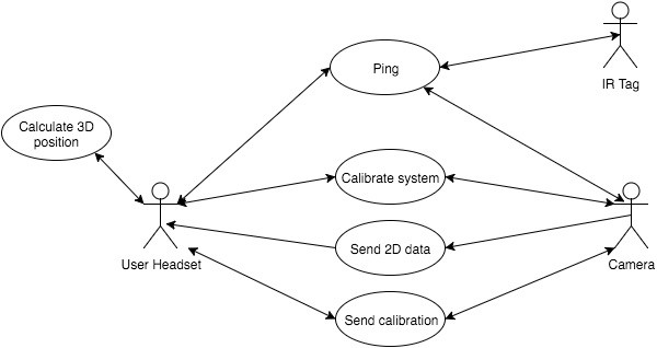
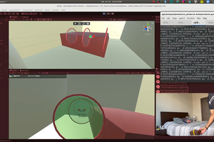
Here is very simply how the different components interacts with each others :


VrTracker general

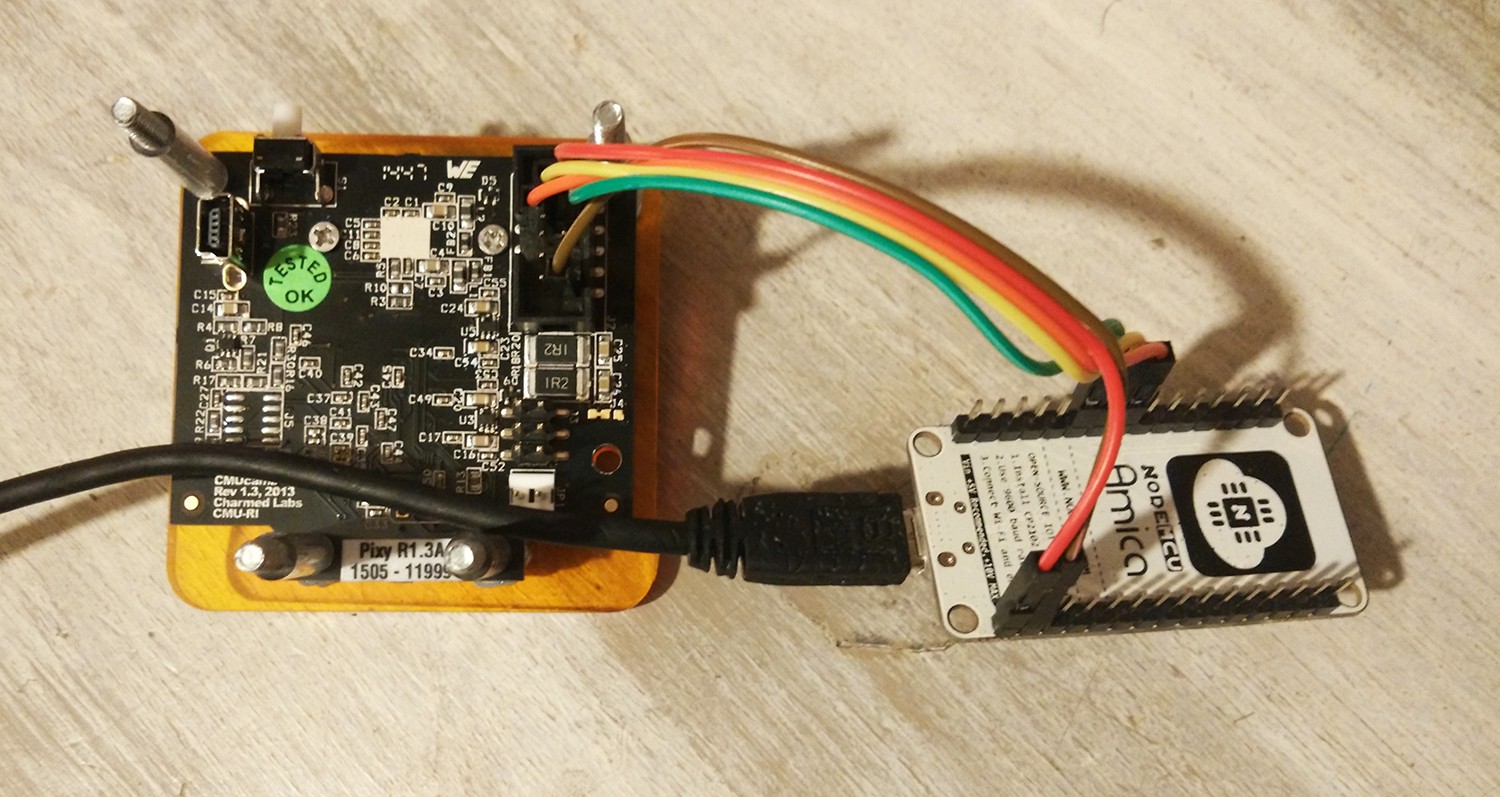
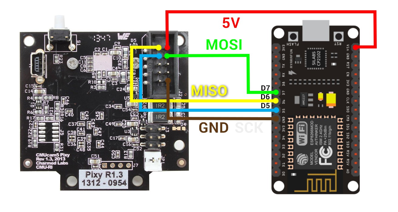
To sum up, the system is composed of at least 2 cameras (CMUcam5) that can track infrared light, an Arduino board with aNrf24L01 wireless transmitter to send the camera’s data over the air. A Raspberry Pi which acts as a gateway to calculate the 3D position from every 2D positions received from the cameras using OpenCV library. And finally an infrared emitter which is going to be tracked.

  • 2 × CmuCam5 (CharmedLabs) Color tracking cameras
  • 2 × ESP12E NodeMCU
  • 4 × IR Leds (SMD 1206 100mA 120°FOV)
  • 1 × Lithium battery 3.7V >400mAh
  • 1 × Resistor

View all 6 components

  • VR Tracker has its own Website !

    Jules Thuillier03/22/2016 at 03:04 0 comments

    Here is VR Tracker brand new website !

    All updates are now on the Blog !

    http://julesthuillier.com/vrtracker/

  • Installation Video

    Jules Thuillier03/22/2016 at 03:02 0 comments

  • Software architecture

    Jules Thuillier02/11/2016 at 19:48 0 comments

    As the project is growing and I would like to release a Unity Asset so that people could start playing around with VR Tracker, I need to develop a software architecture that is stable and could easily expand to more features. Therefore, let's start with some UML to design the software :

  • And here comes the Trello Board

    Jules Thuillier02/09/2016 at 02:38 0 comments

    I think you all know Trello task manager, so here is the board with the tasks left to do : https://trello.com/b/5nqdw4IE

  • Infrared Tag with Wireless Control ?

    Jules Thuillier01/28/2016 at 15:01 2 comments

    If you are reading this, you might have understood by now that we are tracking an infrared light on the user's headset.

    In the first version, the IR leds are simply powered by a small battery and always on. But now, what if we added a little Wifi (ESP8266) chip as there is on the camera to control them ?

    What for ?

    Well if the system is used with multiplayer or if there is some interferences due to sunlight, the wireless infrared tag could be "pinged" to ensure we are tracking the good tag. It would allow to track different users and even "objects".

    What do you think about that ?

  • Big Update : ESP6288, no more Gateway !

    Jules Thuillier01/27/2016 at 18:40 2 comments

    Hi !

    Here is a big update for VR Tracker ! Now the Arduino-NRF24L01+ on every camera has been replaced with a WIFI chip, the ESP8266 (an ESP12E on NodeMCU board).

    Why this choice ?

    Well using Wifi allows to remove the gateway, you can access to your camera directly. Also the code can be updated wirelessly, which is very nice ! Moreover,, for future developments, it will allow a better flexibility.

    Oh and BTW, the chip cost less than 4$ !

    What is going to change ?

    First we remove the Gateway. Therefore all calculations that used to happen in the Gateway must happen the PC / Smartphone. As we are going to use Unity to develop applications and games, we will have to include OpenCV in unity (which can be a bit tricky) and translate the code from python to C#.

    Want a look at it ? Here you go :


    How to plug it ? Here you go !


    The code is coming soon, don't hesitate to ask for it ;)

  • FPS test with ESP8266

    Jules Thuillier01/27/2016 at 17:44 0 comments

    Just tried a quick speed test with the ESP8266. The ESP8266 is using Arduino, connected to the camera (CmuCam5) using SPI and sending data to my PC wwith Websockets (throug a router).

    First test

    I have made a loop on the ESP8266 sending a counter (a 10 bytes char) to my PC. It is not getting any data from the camera right now.

    Result : it sends data at 82 FPS

    Second test

    Same as before, but I am getting data from the camera and parse it in each loop.

    Result : 42 FPS

    As the camera is limited by its 50 FPS speed, it looks like the transmission delay is not that bad !

  • ESP8266 received !

    Jules Thuillier01/14/2016 at 16:40 2 comments

    I just received a pair of ESP8266 wifi chips on a ESP-12E board. They are going to replace the NRf24L01+ / Arduino that were used to transmit infos from the cameras.

    I'll start porting the code right away !

  • A bit more about the Tech...in video !

    Jules Thuillier01/12/2016 at 02:25 0 comments

    Hey ! I have made a quick video (well it's 10min) about the technology : what's inside, how does it work... It sums up all the text much faster ;)

    Sorry for the english / accent....I am french :(


  • Trying to brainstorm a new Software Architecture...

    Jules Thuillier01/12/2016 at 02:19 0 comments

    Here it is, a shot at UML : Link Draw.io

View all 10 project logs

  • 1
    Step 1

    They are two main components in the system : the cameras and the gateway.
    The cameras are based CMUcam5 from Charmed Labs which is a position tracking camera which can output 2D coordinates.

    cmu1

    Why this camera ?

    I have tested almost every alternatives, and the first prototypes were even based on Raspberry Pi camera, and the 2D position tracking was made using OpenCV image library on the Raspberry. I have also been working with the wiimote sensors and many standard HD webcam with FreeTrack. None of them did the job by a long shot !

    You can order this camera on Amazon for 69$.

    CMUCam5 Specs
    • Multi point tracking (great for multiple users)
    • 640*480 @ 50FPS
    • 1280*800 @ 30FPS
    • Lens field-of-view: 75 degrees horizontal, 47 degrees vertical
    • Voltage : 5 to 12V
    • Power consumption : 140mA
    • Open Source (hardware and firmware)
    • Removable optics

    Let's get started, this camera is nice, but we have to add some stuff to make it great. Here is what we are going to do :

    In another post, we will see how to make it wireless, this one is already long enough !

    Get to know your camera

    An important part is to understand how your camera works and how it see the outside world and how it talks about it.
    I am not going to write a lot about it as the guys from CharmedLabs did a great job at explaining all about their product !

    Here is the Main Website

    Technical specifications

    Technical documents

    And her is the Quick Start page to setup your camera for its first use.

    Play around with the camera, connect it to your computer and try to get an image.

    Now you are supposed to know enough about the camera for the following steps. It is especially important to make it wireless.

    Remove the IR blocking filter

    As you have seen on the video above, the camera tracks objects based on their colors. After a little testing, I found out that the color tracking is not good enough for our application, therefore we have to improve the tracking. Here is what we will do : instead of tracking color, we are going to track an infrared light. Infrared light is a light with a wavelength around 940nm, that can’t be seen by humans. Infrared is commonly used in remotes for examples.

    Almost any camera can see infrared even though our eyes can’t. Unfortunately, in most cases we don’t want to see infrared with a camera, so the lens contains an infrared blocking filter. The CmuCam 5 has such a filter in its lens. We will have toremove that filter !

    Different methods can be used to remove IR filters, such as eating the lens until the glue melts. In my case I took a screwdriver, broke the lens and remove the small pieces of glass left.

    Here is how to do it step by step :

    1. Unscrew the lens from the camera
    2. Identify the IR filter. It is on the sensor side of the lens. It has a red-ish reflection like so : eyetoy04
    3. Break the filter with a small screwdriver. Don’t go to far, you would broke the others lenses. Remove the small pieces of glasses left.
    4. You’re done !

    Add an IR pass filter

    Now your camera can see usual light and IR light. As we are only going to track IR, we could add a filter that removes usual light, called “infrared pass filter“. With this filter, the camera will see infrared and only infrared ! The tracking will be much better !

    I am sure you are now thinking “Damn, where am I going to find such a filter ?”, well it used to be easy 15 years ago, today it’s going to be a little more complicated… Here is what you have to find :

    floppyYes ! A goddamn floppy disk !!!

    Because when you open a floppy disk, you see that round plastic thing on the next picture ? Well it can act an IR pass filter ! You just have to cut a small round in this disc with a pair of scissor and put it between the camera sensor and the lens, or at the end of lens.

    open floppy

    Update the firmware

    The firmware inside the camera is made to detect colors, not white (IR) on black. So we have to update that firmware. Thanks to IR-LOCK team, a special firmware has already been made. Those guys use a Pixy cam too on their drones to make a target tracking system using infrared, for automated landing and much more ! You can also order a Pixy Cam right from their website with the right lenses and filter and a bunch of infrared LEDs If you prefer for 99$. I wouldn’t personally recommend it if you are low on budget, but if you want to gain some time, it could be a solution.

    To download, install and configure the new firmware, please follow instructions 2 – 6 on IR-LOCK Getting Started page.

    Now you can start playing around with infrared tracking 

    Build a case

    This step is not necessary, but I am going to give you all the steps and files to make a nice case for your camera and wireless module (we’ll talk about that a bit later).

    The case is very easy and low cost to make. It is not the most beautiful case ever, but it will be practical and won’t require any tools (except a screwdriver).

    The case is made of two pieces of plastic, laser cut, assembled with a few screws.

    Camera support 2D bottom Camera support 2D topbothtopbootom
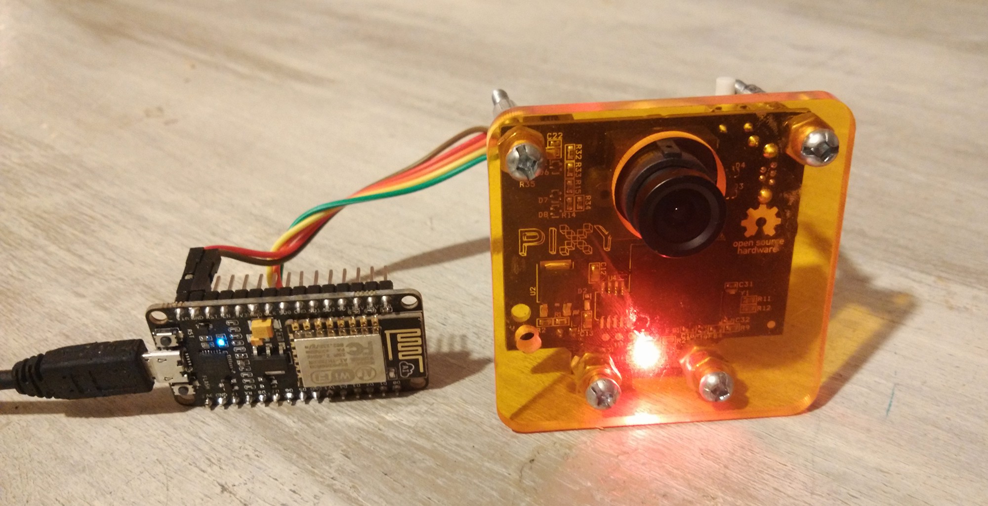
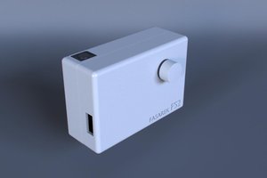
The camera and its wireless transceiver are sandwiched between both PVC parts as you can see here :VrTracker Cameras
    If you have never made any laser cutting ever, here is what I usually do :
    1. Go on SeeedStudio Laser cutting service
    2. Upload the following files Case CAD (you have to do it twice, once for the bottom and once for the top)
    3. Finish the order (login, shipping…) and should have 5 cases delivered to your home for less than 20$ !

    Once received, you just have to find some long screws and assemble everything !

    Note : If you are planning to order on SeeedStudio, you might want to order the PCB for the wireless transceiver at the same time. So checkout the next article on this subject.

    In the next step, we will make an electronic circuit to make the camera wireless. I’ll give you all the files and instructions to build it yourself ! It is in another post as this is pretty long…

  • 2
    Step 2

    Let's sum up what we have done so far :

    • we ordered a pair of color tracking cameras
    • we modified them into Infrared tracking cameras
    • we updated their firmware to track Infrared and tested them
    • we built a small case to give them a nice look

    There is one last modification we have to bring to the cameras, and that modification is a game changer : we are going to make them wireless !

    Of course we won't send the video, but the coordinates of the points the camera is tracking. In this article we are going to connect an ESP8266 Wifi shield to the CmuCam to send coordinates over Wifi.

    Here is what we are going to do, step by step. All you need to know for this part is how to program an Arduino (I have seen 8 years old doing it so...I'll give you a link just in case).

    The basics

    Here we'll go through all you need to know to make it out of this tutorial alive.

    First if you don't know what is Arduino, please read about it here : Arduino.

    We are not going to use a regular Arduino board but an ESP8266, which has been made compatible with Arduino. To make it easier, we will start with a NodeMCU dev board which includes an ESP12E (which includes an ESP8266 ^^) and a USB programmer :

    NodeMCU_DEVKIT_1.0

    You will need one per camera, but luckily you can find them starting at 3.28$, shipping included on Aliexpress.

    Connect NodeMCU to CmuCam

    Here is how to wire the CmuCam to your brand new ESP8266 :

    Pinout ESP12E NodeMCU CmuCam5

    Program the ESP8266

    We won't go through "How do we install Arduino IDE", if you are still reading this then I'm sure you'll be smart enough to know how to use Google ;)

    For this part first go here to learn how to use Arduino with an ESP8266 and configure your Arduino IDE.

    You should install the following library for the camera (please use my version otherwise it won't work with the ESP8266 : Pixy ESP8266 library (more documentation on the library here).

    Make sure to download (from the Arduino library manager) all the libraires required for Wifi connection.

    And here is the code you have been waiting for. Here is what is does :

    1. Turn the ESP8266 into an Access Point so you can connect to it and enter your Wifi informations
    2. Try to auto update from a server
    3. Start communication with the camera, and broadcast datas over Websocket (it acts as a websocket server)

    Please note that it is a very early version for tests purposes. Major fixes and improvements are yet to come.

    https://codebender.cc/sketch:207000

  • 3
    Step 3

    Behind the curtains : calculating 3D position by image resectionning

    The system uses OpenCV to calculate the 3D position form multiples 2D positions.

    First a calibration sequence is required. The calibration consists of recording some 2D positions with the cameras and associate them to real 3D position. I’ll make a quick video about that. You have to recalibrate every time you move the cameras of course.

    With the calibration and some OpenCV functions, we are then able the deduce the 3D position of each camera. With that position and we will be able to get a projection matrix and then do some triangulation !

    Yes, to sum up we are going to do some regular triangulation !

    But first we have to create a Unity environnement and import OpenCV. To do so we will use EmguCV, which is a cross platform OpenCV wrapper, compatible with PC, Mac OS, Iphone, Android... all we need for our applications.

    Then we need to communicate with the cameras using websockets.

    Finally we have to create a calibration sequence using OpenCV and add the tracking function. All of this had been done in the previous version using a Gateway, but I now have to translate all the code from python to C# and clean it of course.

    To be continued...

View all 3 instructions

Enjoy this project?

Share

Discussions

Natetoon wrote 08/19/2021 at 02:09 point

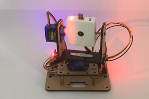
so I actually want to use this to set the rotation and orientation of a game world, to match a real world. similar to the void, so put the camera onto the headset itself, and then set the trackers to the wall. and use their coordinates to set various points. to have multiple level setups, yet reset the tracking to the environment. do you think that is possible?   

  Are you sure? yes | no

Tobias Hübner wrote 10/13/2016 at 18:15 point

Hello, 

thanks for your tutorial how to build the VR Tracking system.

However, can you please explain how to build the tags including IR LED, gyroscope and accelerometer?

Thanks.

  Are you sure? yes | no

mikele wrote 01/31/2016 at 12:45 point

Thank you very much for sharing your development and ideas it is very stimulating. If you are putting openCV libraries into the client maybe you can use the camera in the moving target/user for traking the movent. Also If you put one marker/traked object in the middle of the ceiling you can get the xy moving plane coordinates. Maybe changing the 75 degrees lens for 145 degrees is needed http://www.m12lenses.com/2-1mm-F2-2-Board-Lens-p/pt-02120.htm. This also can be good for multiple rooms , and to avoid problems with infrared daylight . Sorry if i´m missing something obvius o this aproach but maybe it can work? I´m ordering a cmucam5 and a esp8266 right now for checking :-). Thanks again for sharing your work, i´m VR developer and this tracking feature is very interesting to include in any vr experience.

  Are you sure? yes | no

Brendan Walker wrote 01/15/2016 at 06:10 point

Thanks for sharing this project! I've been working with some people on a VR PSMove Controller library for the PC. You can see a demo of the Unity library here: https://github.com/brendanwalker/psmove-unity5. Currently the library is embedded directly into your application, but this has a few problems (mostly to do with camera driver issues). Right now myself and the maintainer of the Unreal version of the library are making a Windows service similar to your Gateway for psmove controller data. After we get this done I had wanted to make the library work on the GearVR. I just came across your library today and it looks like exactly the missing piece I needed to make a GearVR port of the library happen. So thanks again for making this and documenting it so thuroughly!

  Are you sure? yes | no

Jules Thuillier wrote 01/26/2016 at 20:18 point

Hi ! Thanks for your feedback. Great project with the VR PSMove by the way !

Glad this project could help you ;)

  Are you sure? yes | no

Sam P wrote 01/08/2016 at 13:51 point

This would be awesome to combine the real and virtual worlds and allow you to physically touch things! I'm wondering how difficult it would be to expand this to work with any number of cameras. Also you could eliminate the need for a raspberry pi and arduino by using an ESP8266 connected directly to the camera and send the data directly to the PC using UDP packets over WiFi.

  Are you sure? yes | no

Jules Thuillier wrote 01/10/2016 at 00:12 point

Hi !

Funny you talk about the ESP2866, I am waiting to receive a bunch of those chip to replace the Raspberry / Arduino / NRF24L01 ! 

This system is totally compatible with AR headsets too even though I don't think the technology is mature enough now...

The goal is to b able to use it with any number of cameras as you said, and it wouldn't be difficult, but it would require to spend some time on a nice software architecture ! If some people are ready to contribute to the project to make it a great and strong system, it would be awesome !

  Are you sure? yes | no

Sam P wrote 01/10/2016 at 17:03 point

I'd be interested in contributing if it weren't for my other projects sucking up time/money. Are you using a particular game engine for development right now?

Edit: Never mind, just noticed you mentioned Unity in your video :)

  Are you sure? yes | no

Similar Projects

Does this project spark your interest?

Become a member to follow this project and never miss any updates