 Nick Sayer
OpenEVSE II starts by separating the HV and logic systems. The display board, which was optional for OpenEVSE, is mandatory for OpenEVSE II. It includes the display, controller, a real-time clock chip and a temperature sensor (to allow thermal shutdown). It is designed - as the OpenEVSE display board is - to be a "backpack" on an RGB backlit 2x16 LCD module. It has just about all of the low voltage logic, which means that troubleshooting can be done on the bench with nothing more than a +12 VDC power supply. It draws less than 100 mA of 12 volts in operation. There is a buck converter on the logic board to make 5 VDC along with a charge pump inverter to make -12 volts.
The logic/display board also includes the pilot generator and state transition monitoring systems, a GFI (with a test circuit), and an ammeter (based on a current transformer).
The logic/display board connects with a 10 pin FFC cable to the HV board. The HV board can drive either a line-powered contactor, or an external 12 VDC relay.
The current rating of the design is limited only by the ampacity of the relay or contactor and the wiring of the high current path (which includes the power and J1772 cabling).
The HV board is responsible for supplying 12 VDC power, switching the relay or contactor on and off, and performing the stuck relay and ground continuity test. It also has an opto-isolated voltmeter, which allows OpenEVSE II to monitor power consumption rather than just current.
The GCM/relay test system starts with the Relay Test terminal, which is connected to the load side of the main switching relay/contactor. From there, each leg is fed into an S1M diode and the two are merged together. The result of that is that for split phase systems there will be 120V positive going half-sine pulses at 60 Hz and for hot-neutral systems there will be only one pulse at 50/60 Hz with a missing pulse between each. The voltage will be either 170 volts (for North American power) or 320 volts (for hot-neutral 230 V systems). This requires a resistor of either 150kΩ or 300kΩ depending on where you are. The desired goal is for a 1 mA current to be reduced under the maximum working voltage of the LM334 (40V). The LM334 will pass a maximum of 1mA through the diode of the optoisolator, whose cathode is connected to ground. This circuit path represents an intentional ground fault, albeit one whose current is limited to a maximum of 1 mA, which should be safe enough, as it's only allowed when the power is on, and if the ground connection isn't good enough, it won't be detected and the software will refuse to charge. The secondary side of the optoisolator is a simple current transducer followed by a comparator to detect when there is current flowing in the primary. The output of the comparator feeds a capacitor with a bleed resistor so that the ripples caused by the input AC don't get passed to the firmware.
The voltmeter is built around a precision optoisolator. The precision optoisolator simply has two secondary phototransistors that are very closely matched. The one on the primary side is used as part of the feedback loop of an amplifier driving the LED. This insures that the response of the system is very linear despite the vagaries of temperature response and so forth. Since the secondary phototransistor is well matched, the linearity of the secondary output is implied. The input of the voltmeter is fed from a voltage divider (with a blocking diode) across the two AC lines. The two resistors are very lopsided - 1 MΩ and 12 kΩ. The result of that is that a 240 Vrms input will be about 4 volts output (with the "common" of the circuit being one of the AC legs). Since the voltmeter has an Op amp, it requires DC power, but this DC power has to be relative to the common point of this portion of the circuit, which is actually one of the AC legs. To do this, we use an isolated DC-DC converter module. It takes 5 volts in from the logic system and...
Read more »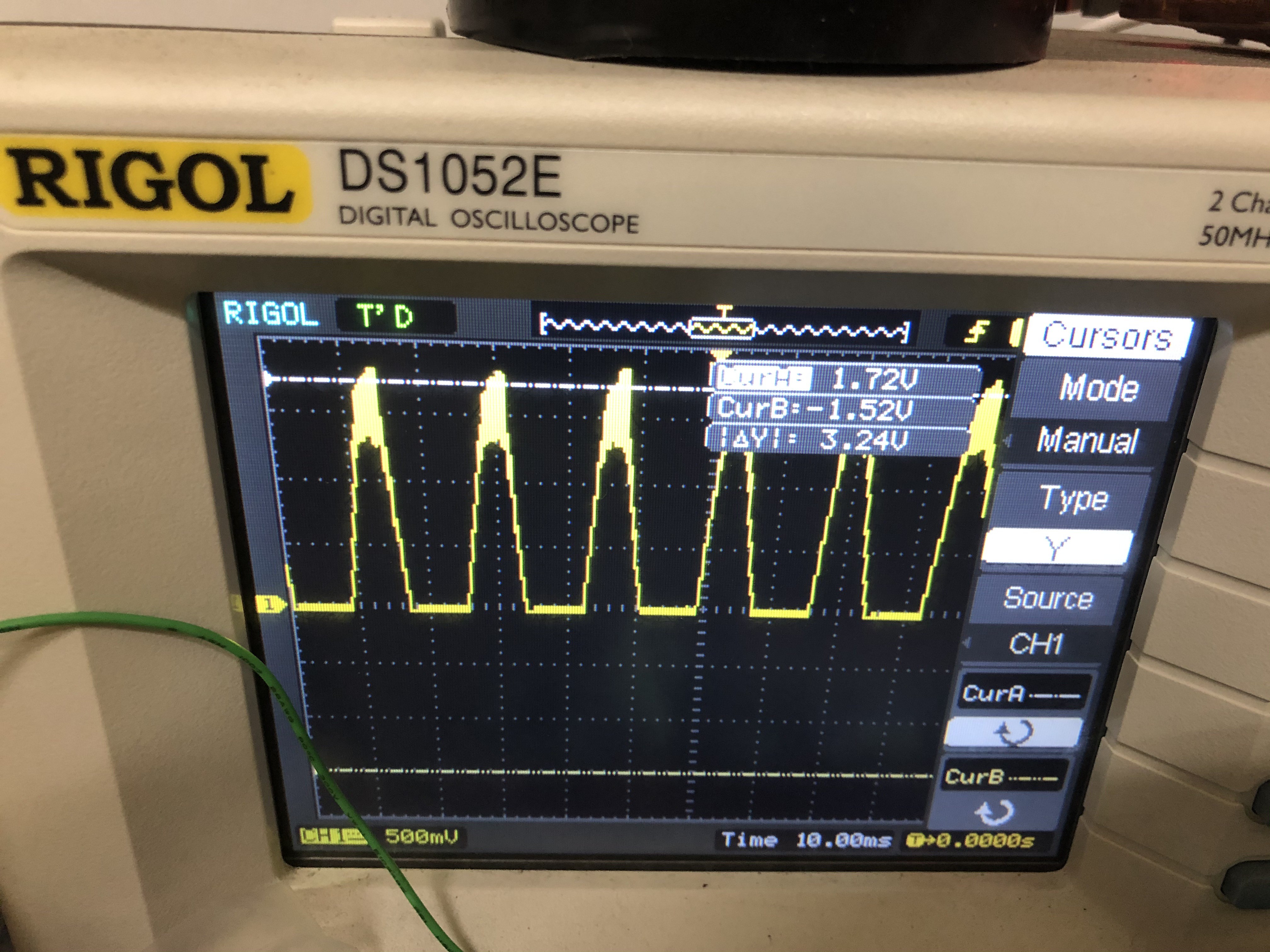


 Bharbour
 Ken Yap
 Quinn
Quinn
I like the idea of the project. However I would like to leave some comments.
Idea is very good from the experiment standpoint however far away from production ready.
Display board has connections to GFI CT, measuring CT and the pilot, as well as flat 10wire. How are you planning to connect/disconnect in the real world when you expect the display screw mounted on the lid?
screw connectors are not something I would like to see on the display board along with the delicate flat connector.
Current transformer leads are usually short as well so connecting them directly to the screw terminals doesn't seem like a good option.
I would like to see pin terminals which could be easily disconnected by pulling the wires so the components won't be damaged if someone unexperienced did not read the warning labels or disassembly instructions, expecting something sturdy and in fact having gentle components damaged right at the beginning.
So far, the only big improvement is the voltmeter onboard which eliminates the guesses what the input voltage is. I would consider buying a batch when the comments are addressed.