0%
0%
Universal Battery Module
The goal is to create a bulletproof 18650 based battery solution applicable to a wide variety of tasks; solar, utility vehicles, EVs, boats.
 Ampeater
Become a Hackaday.io member
Already have an account? Log in.
Just one more thing
To make the experience fit your profile, pick a username and tell us what interests you.
Pick an awesome username
hackaday.io/
Your profile's URL: hackaday.io/username. Max 25 alphanumeric characters.
Pick a few interests
Projects that share your interests
People that share your interests


 Jarrett
 Kane
Kane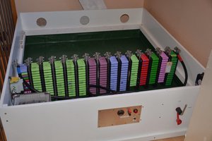
 Michel Kuenemann
 Ultimate Robotics
I have two projects, one is my job and the other is a hobby.
Job: 11 module 48V LiFePO4 batteries 70KWh/
Hobby: hack an old LG 14 module Li Ion rack to use as solar storage in a 30kW solar + storage system. I have no controller for this system so I am trying to replace the OEM canbus BMS with DIY or OTS BMS.
My name is John