 Evan
EvanPreface
The following content is pulled directly from the lab report that we wrote describing this project, so if you're having trouble understanding anything here please, please don't hesitate to send me a message and I would be more than happy to explain it on a less technical level!
I did not build this project alone! Much of the design, all of the motor circuit design, all of the Verilog, most of the cable work, and most of the CAD were done by my partner Kyle. I did the primary work on the LED control software and the control board design and population.
Overview
Persistence of vision (or POV) is the phenomenon by which the eye, seeing a rapidly moving objects, stitches together the object’s position at different times into a single cohesive image. This phenomenon is leveraged by CRT displays, which use raster scanning to draw individual pixels in each horizontal scanline before returning to the beginning of the next one. In contrast, our spherical display displays scanlines vertically. We have built a spherical display that creates a picture by rapidly alternating the colors displayed by each of a column of LED pixels. Each column of vertical pixels displays simultaneously. The physical location of the light source is then moved by a short distance before the subsequent vertical scanline is displayed.
Our system consisted of a 60-pixel LED strip mounted on an acrylic ring, which was lined with a 60-pixel LED strip running an array of LED pixels. Its bottom is mounted to a 6V DC motor with an encoder which uses a Hall-effect sensor to accurately determine its position. The motor’s rotational velocity is set to 500 rpm. A 6-wire slip ring from Adafruit allowed us to connect the LED power, clock, and data lines from a stationary frame to the rotating acrylic ring. (Since 6 wires are available, 2 wires each are used for power and ground lines.)
Our system's frame was constructed from scrap wood. The ring that carries the LEDs was 12" in diameter and laser cut from 1/4"-thick acrylic. 60 APA102 LEDs from Adafruit (strip density of 144 LEDs/m) were attached to the ring with CA glue. The top and bottom of the ring were both sandwiched between two 3D printed couplers, which contained a hole for the four LED wires (on the black encoder) and the motor shaft set screw (on the purple encoder).
The motor is mounted inside a square of scrap wood which is bolted to the bottom of the frame with four metal standoffs. The motor is glued into the wooden square. The bottom plank underneath the motor is drilled out so that the motor can be set deeper inside, but the motor itself cannot actually be snug inside the plank, as the fragile encoder on the bottom needs to be able to rotate freely. Additionally, the motor's 500 RPM rotation speed creates a lot of scary vibrations, so we added a little bit of damping on the top of the frame; hence, the brick weight seen in the pictures of the device in action.
- The Raspberry Pi sent 3.3V data out into a level shifter which sends 5V SCL and SDA lines into the LED strip. It also sends two lines into the FPGA: “Motor Toggle” and “Reset”. The +5V and GND input lines on the control board are spliced into a microUSB cable, which powers the Raspberry Pi.
- The FPGA receives the previously mentioned control lines from the Raspberry Pi. It also sends 3.3V from its regulator to the encoders on the DC motor. It...


 Andrew Kotite
 Alexis
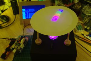
 bornach
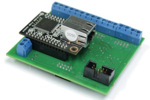
 Yann Guidon / YGDES
Love this, and been thinking of making something similar for a while!