Close
0%
0%

Big Ol' Modular CNC

It's Time.

Similar projects worth following
It's time to build a CNC, dangit!
I keep looking into ways to do-so, but now I've actually started something.

One axis, so far, and some intention of keeping each axis somewhat modular, so e.g. this first axis could be used for a drill-press. This and the second axis (planned, but not yet built) could be used for e.g. a laser and for lathing. Those two and a third could be used for e.g. milling, PCB-routing, etc.

An automated drill-press with no other axes doesn't make a whole lotta sense, but since this is highly geared-down, the plan is to have a second motor attached to a manual lever. That motor's encoder will be used to detect the position of the lever and move the axis-motor accordingly. A feedback loop will allow for force-feedback on the lever-motor, allowing me to "feel" the drilling process just as one would with a normal drill-press.

If you look through my projects you'll probably see that I've got a lot of *plans* for CNC systems, but nothing actually built, yet...

There's:

It's time for me to build my own CNC system, dagnabbit!

A couple months back I got completely fixated on it and assembled the first axis from stuff sitting in my stockpiles.
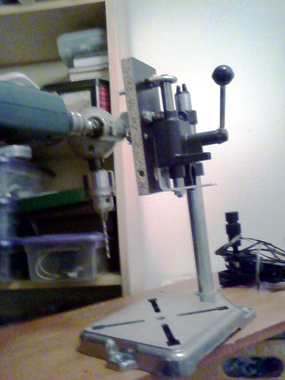
The first necessity: a "drill-press." Those rails are 1/2in in diameter, so I needed to drill 1/2in holes in the particleboard end-plates. Doing it with a hand-held drill would be difficult. Drilling both plates at the same time would assure the holes' alignment, so the rails would be parallel, but drilling perfectly vertically would require a jig, what better jig than a drill-press? Additionally, my hand-held drills don't have chucks large enough for a 1/2in drill bit, so...

#rotary-tool-drill-press to Drill-Press conversion
Back to the first axis of this "Big Ol' CNC":

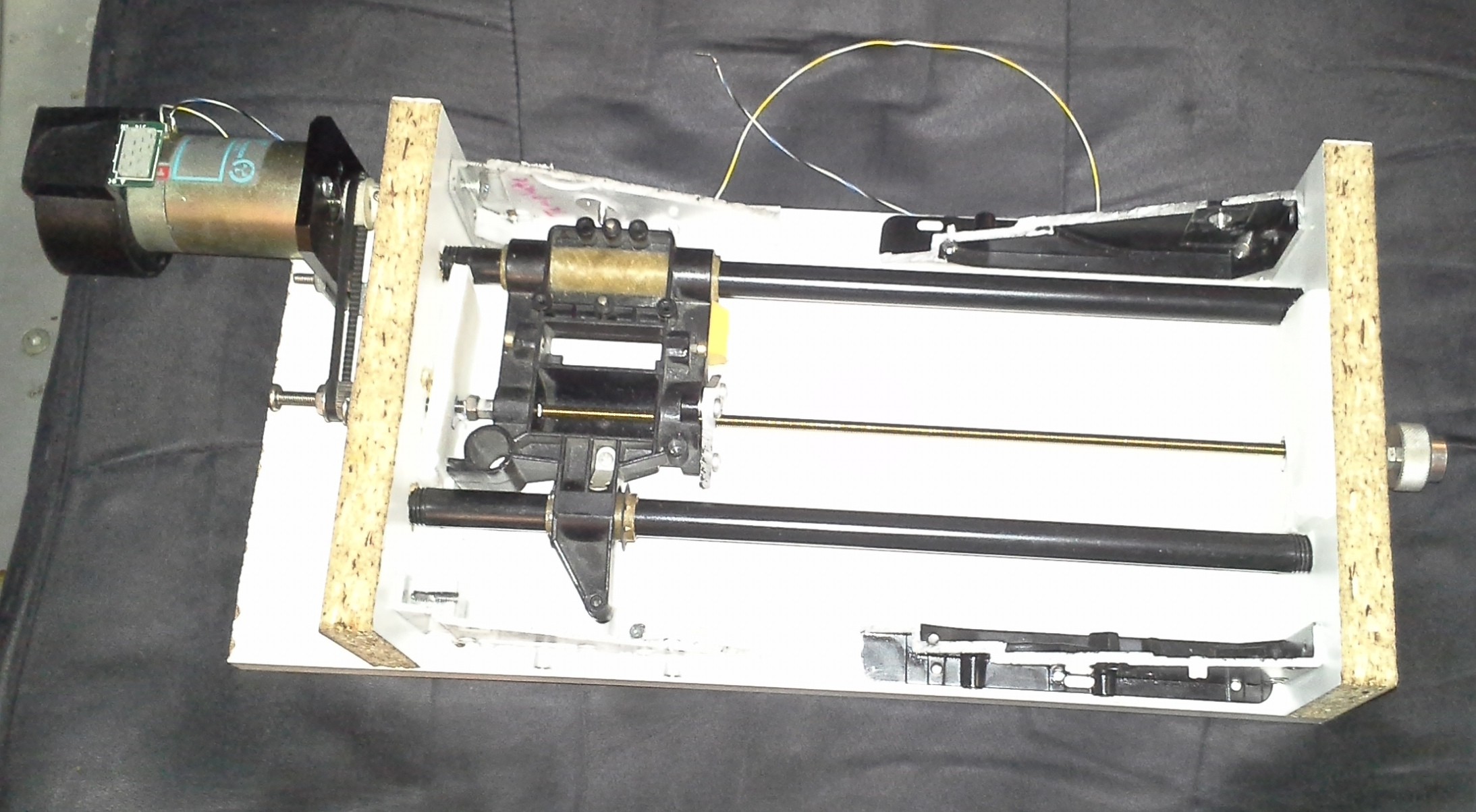
The "carriage" is from an old dot-matrix printer. It came with its own leadscrew, but it was something like 1in per turn, much too high for my intentions. It also came with rails, but I have no idea where they wound-up. The black rails are nothing more than pipe... not sure where they came from. They are a little bit tight and you can feel differing amounts of drag at different positions, but it seems OK, for a first-go.

The leadscrew is just a piece of threaded-rod I had laying around that was about the right length. I think it's 10-32. It's a little short, so I found a metal stand-off that was long enough but 6/32, so drilled it out and rethreaded it. Then I butted the threaded-rod against a long bolt of the same threading.

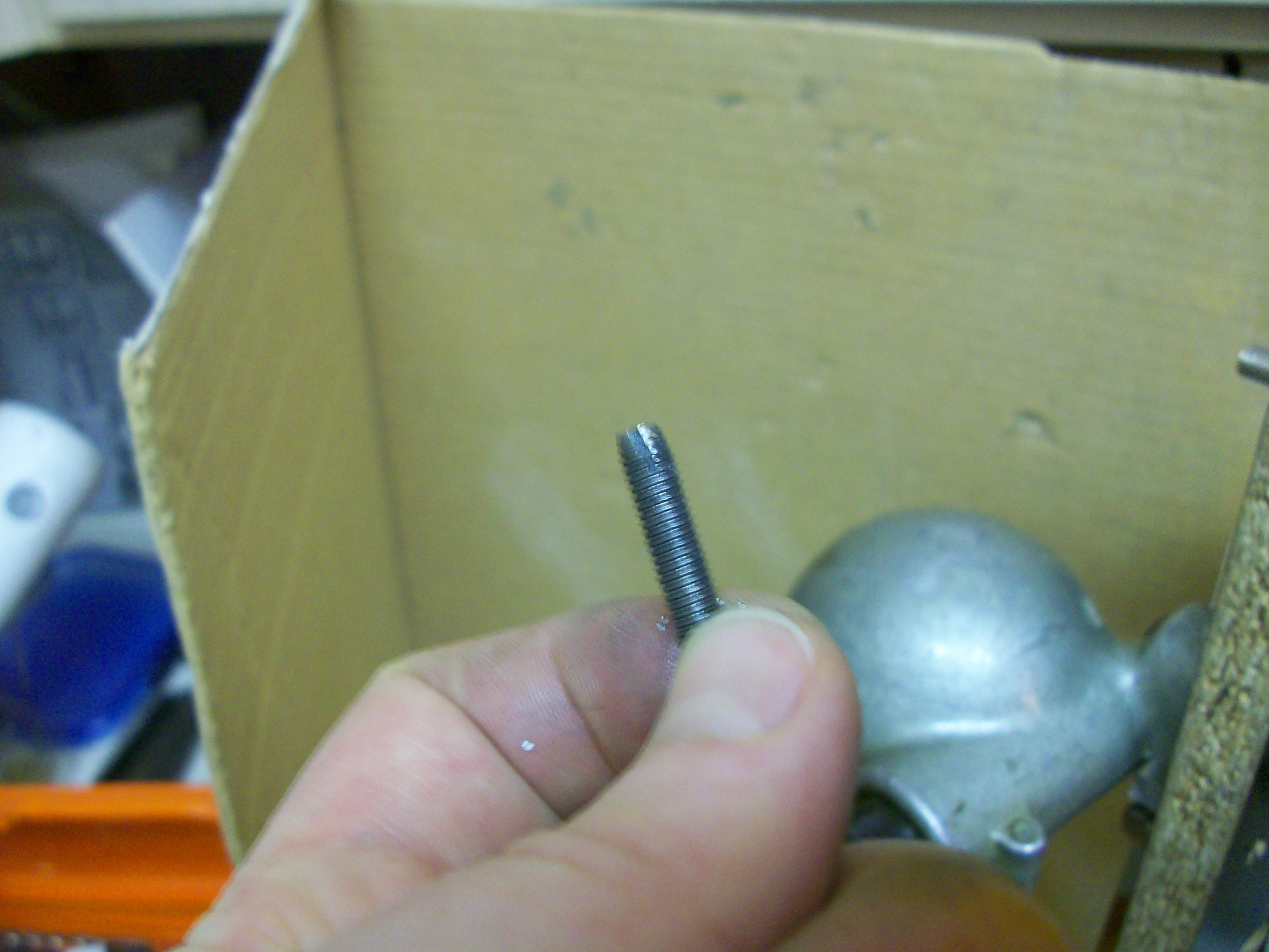
Below is the home-made tap, from a bolt, a little filing while spinning in a drill, and a cut-off-wheel.

(TODO: Better notes on making a tap! Or just link to the part in the drill-press conversion project).


The bearings at either end (not visible in the first picture) are much too large inner-diameter for the threaded-rod, but I just happened to luck-out that some of the nuts in my possession had rounded edges, so when tightened against the bearing cause the rod to center darn-near perfectly. Two nuts on either side lock them in place.
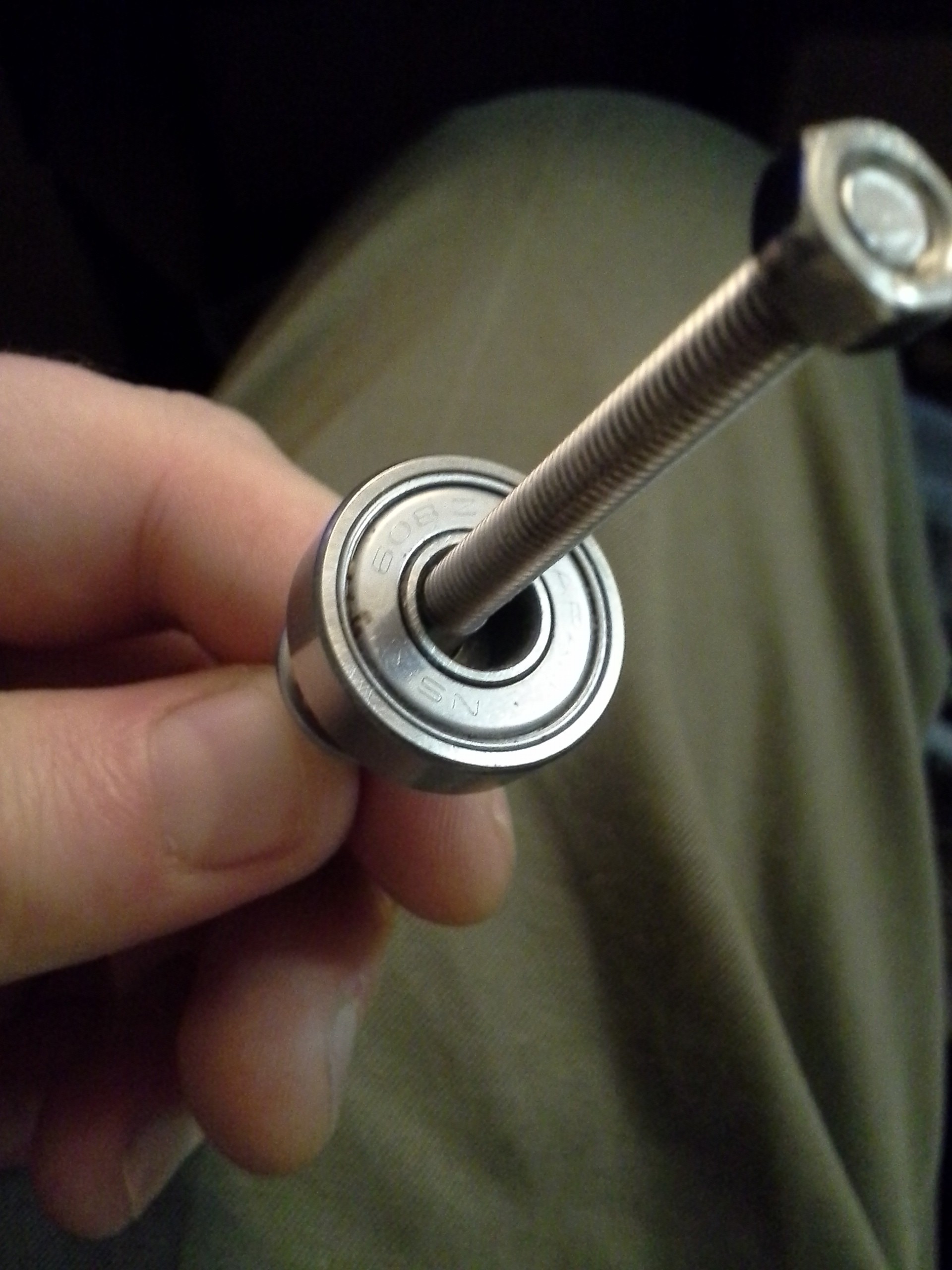
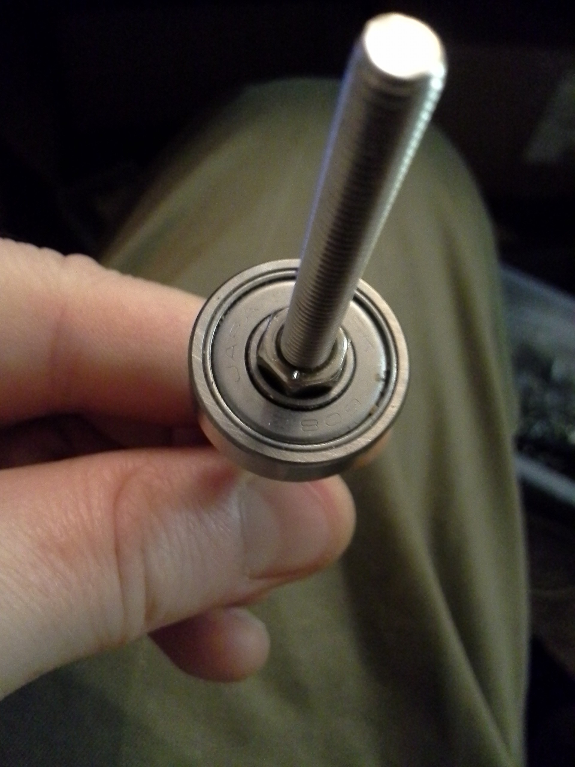
The bearing on the motor-end is held in place with three large-headed screws. The bearing on the "knob" end is held in place merely by friction and tension (wow!).
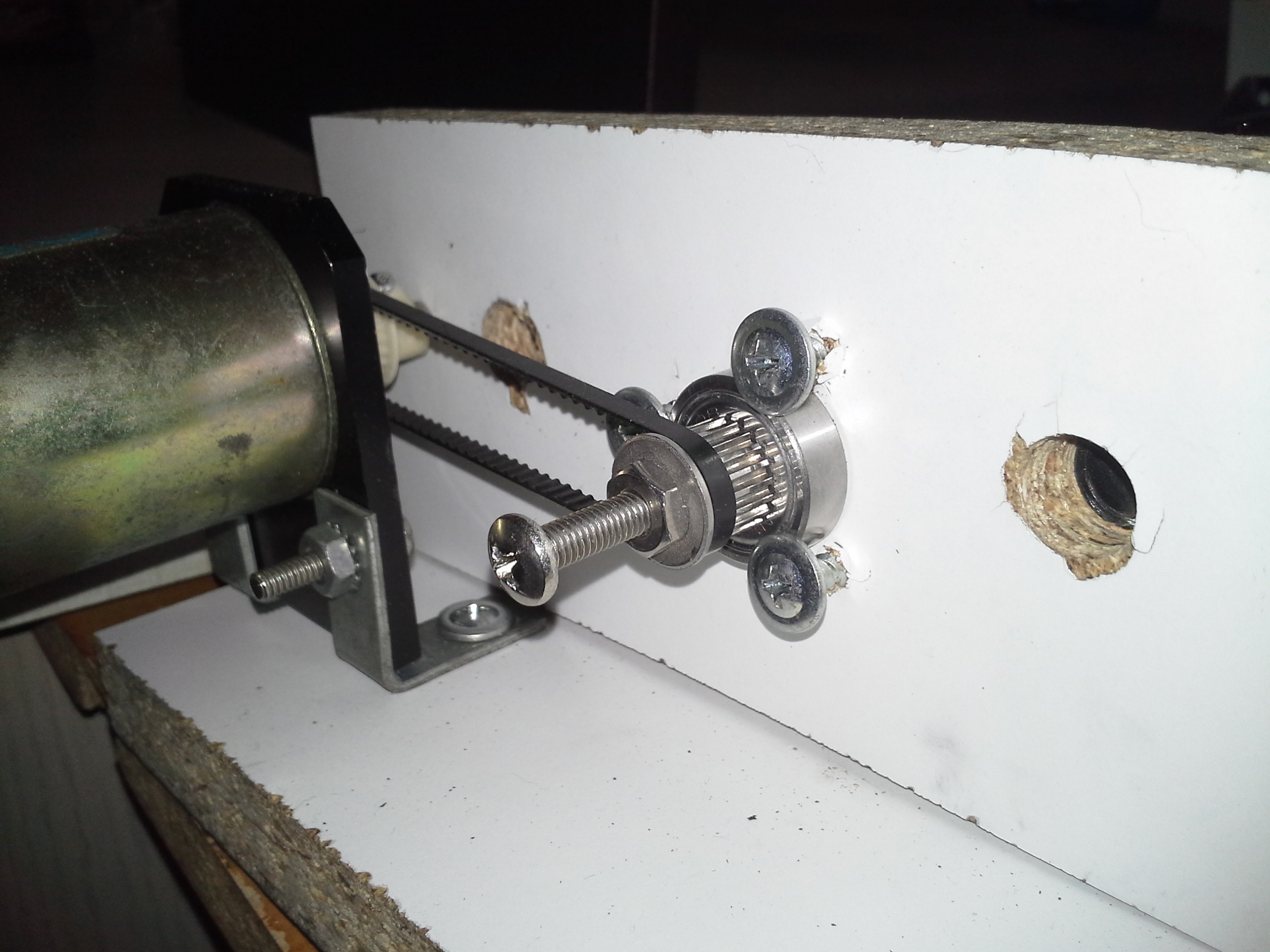
Friction/tension wouldn't work for the motor-end, since the belt needs to be pulled tight. I tried to make a nice calibrating mount with a ring (again from a hard-drive) and three screws facing inward, but that's where I wound-up breaking my small tap.

You can also see, quite clearly in this photo, just how accurately my electric saw cuts... Believe it or not, I mounted (and followed) a guide to cut a straight line, the blade managed to wander despite the guide. Wee! I've tried several attempts, several techniques... I'm pretty sure it's play in the saw. But it's good 'nough, eh?

-----------------

In the first picture you can see foam-core board at either end of the axis. (Thanks #Travelling Hacker Box! I never guessed how handy this stuff'd be!). I used it to find the center of the threaded-rod, once mounted in the carriage. I unscrewed the threaded-rod until it *just* protruded from the carriage, then slammed the carriage against the end-plate/foam-core. This put a nice divot in the foam-core. Then I poked through that with a pen-tip or something, and used that hole and the foam-core as a temporary bracket to hold the threaded-rod in position on both sides as I positioned the bearings, tightened nuts, etc.

The threaded-rod is attached to the carriage via a plate I made by hacksawing a triangular piece of aluminum...

Read more »

JunkTest.gl2.licensed.eps

Interlocking donuts converted from HP-GL to ecapsulated post-script (open with inkscape). This is much less fun to watch, seriously, the process has to be watched-drawn in realtime to enjoy its effects. Converted with 'hp2xx -m eps JunkTest.gl2.licensed'

x-eps - 96.84 kB - 06/19/2016 at 06:55

Download

JunkTest.gl2.licensed

HP-GL interlocking donuts. This is quite fun to watch drawn on a plotter, as it draws squares randomly around the page until the image comes together. This was given me by a friend many many many years ago, unfortunately I don't remember his name and haven't his contact info, so this is provided just "for fun."

licensed - 50.29 kB - 06/19/2016 at 06:55

Download

  • Relateds + Audio-Amp Motor-Driver

    Eric Hertz10/30/2016 at 12:40 0 comments

    This project has fallen to the way-side...

    There've been lots of related-sub-projects since the last log...

    I should link those. (TODO)

    One is @johnowhitaker's #Mini PCB printer, which I'm ecstatic to be a part of.

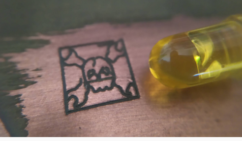
    This guy uses a laser-diode from a DVD-drive to melt laser-printer toner directly onto bare copper-clad board as an etch-resist. There's a bit of fine-tuning involved, but I think with enough practice this could be quite the interesting/useful technique for many things. PCB-etching, of course. Also, maybe, creating "silk-screen" style labels for instrument-panels, and more. It's a bit of a bummer I've not put more effort into that fine-tuning, as I really think this could be useful.

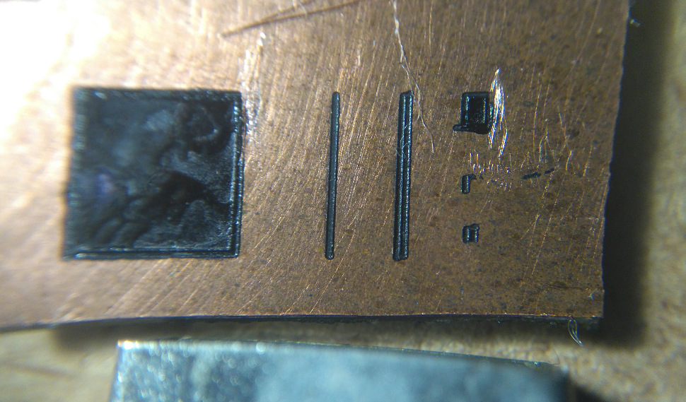
    johnowhitaker is *way* better at getting actual CNC-machines up-and running than I... Here's my first "hand-drawn" experiment, which was very promising, the squiggle in the upper-left.
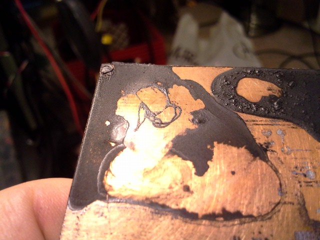
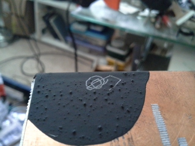
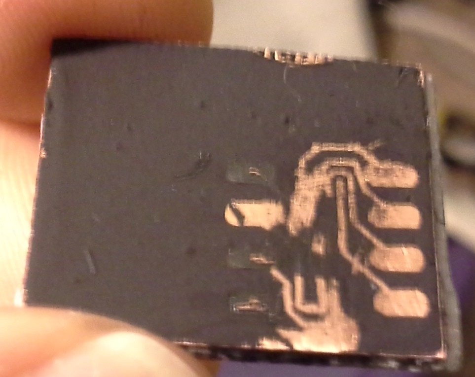
    Interesting aside, just occurred to me. A little setup, first: Using this method makes a "trace" of solid plastic wherever the laser passed-over.


    When the laser's not adjusted to the right power to heat the underlying copper, that solid plastic trace doesn't adhere to the copper, and can actually be pealed-up from the surface. This might be useful for, e.g. "isolation-routing"

    Or, which I just-now thought of, creating a stencil/silk-screen. Again, for face-plate labels, once the solid "traces" are removed, the labels could be spray-painted onto the surface.
    Hmmmm... Similar could be used for spray-paint solder-masks... Hmmm...

    ---------

    As far as its direct-relation to *this* project... Well, briefly, I've ported GRBL to PIC32 and abstracted it a bit so it should be more-easily ported to other architectures. Additionally, I added the option for direct-control of steppers via directly-wired H-Bridges (rather than using Step/Dir stepper-driver boards), which should also be somewhat easily modified for e.g. driving DC-motors with optical-encoders (like used in this project). That GRBL-abstraction was a *much* larger undertaking than I expected. But now that it's been done, any further modification should be quite a bit simpler.

    GRBL, of course, would be quite-handy for this project. I'd already developed HPGL-based software to do the same... it's not perfect, but definitely functional. And, usually, I have a tendency to "reinvent the wheel." But G-Code is well-supported these days, and G-Code "senders" are pretty-durn-sophisticated. So, a new path for me: abandoning my old home-brew motion-control software in favor of something much-better-established, more fully-implemented, and open-source.

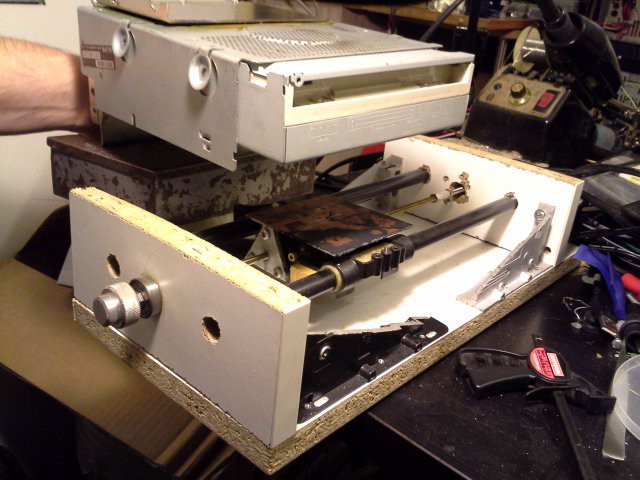
    Haha, here's a ridonculous image where I tried to use this project for long/skinny PCBs:

    It's not a bad idea, but gravity doesn't have to be your enemy, and in fact can be your friend (In other words: turn the danged setup on its side!)
    -------------

    Oy, none of that was even the point of this log... The point of this log was:

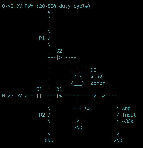
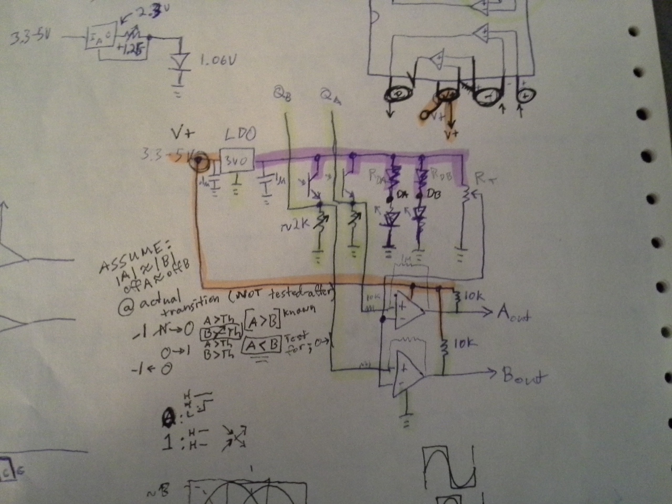
    I ran out of solderless-breadboards, so had to take apart one of my old projects, which *was* for this project... and I wanted to make sure I had the schematic somewhere so I could repeat it... Whelp, I didn't put that on this project's page, for some ridonculous reason... and finding it was a pain... so here it is:

    https://hackaday.io/project/8348-random-ridiculosities-and-experiments/log/30714-groovy-circuit-explained


    Briefly: I'd been doing experiments with using linear audio-amplifiers as motor-drivers. Not sure exactly why, but definitely a curiosity, and I'm pretty proud of that circuit... That circuit takes a PWM-input, toggling between 0V and 3.3V, and outputs an analog voltage that varies, roughly, from -1.5V to 1.5V. (Yeah, I have a single-supply linear audio-amplifier chip which requires a 0V-centered input-signal. Weird, eh?) And, I think, this circuit can be tuned such that quick/large-changes in PWM-value result in pretty-quick changes on the output-voltage, but that has yet to be thoroughly-explored.

    If curious, check around the logs at that project-page...

    Read more »

  • Ridonculous Encoder Endeavors

    Eric Hertz02/24/2016 at 14:16 0 comments

    my old "oneAxisHolder" project was AVR-based and ran on 5V...

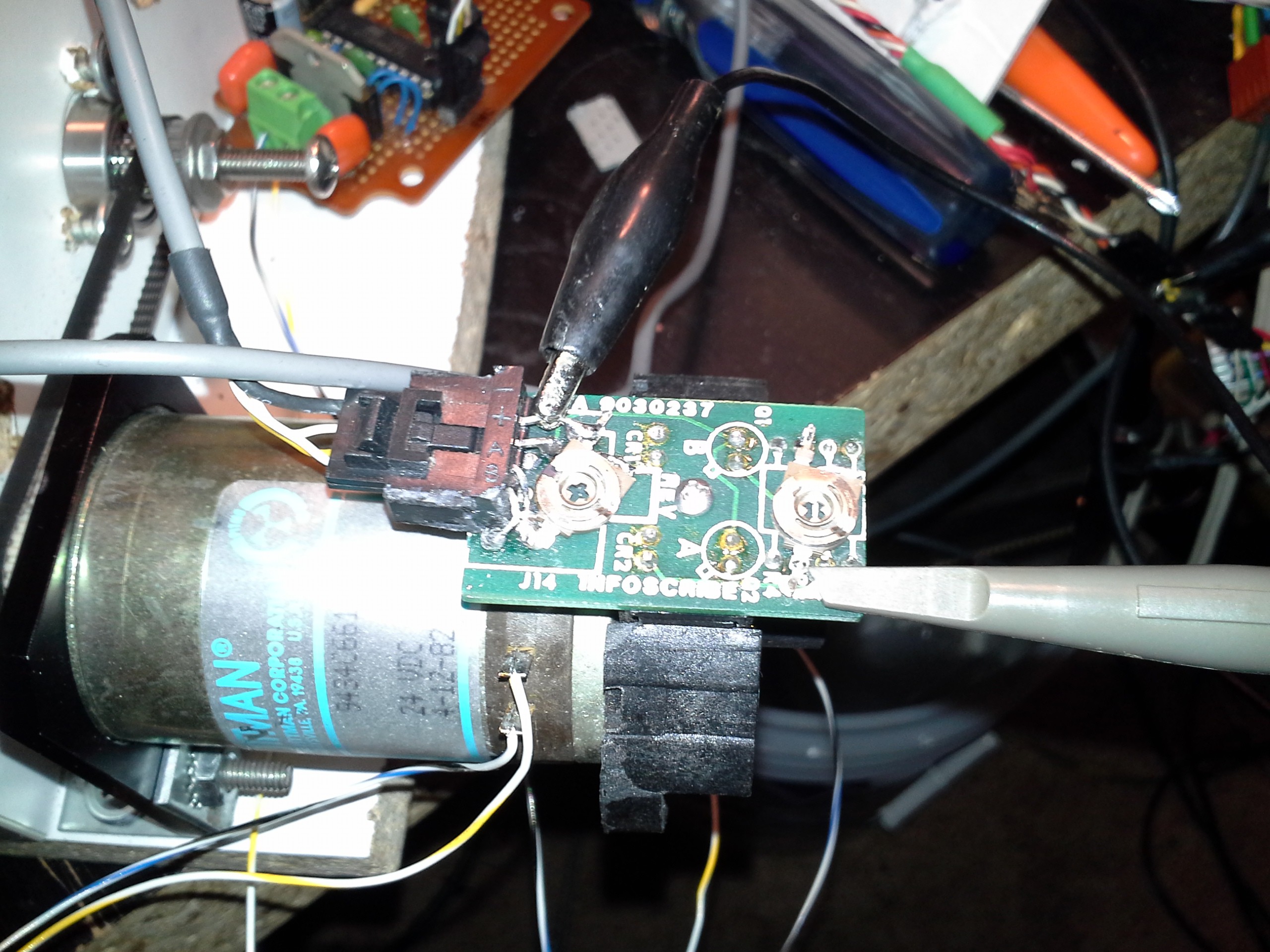
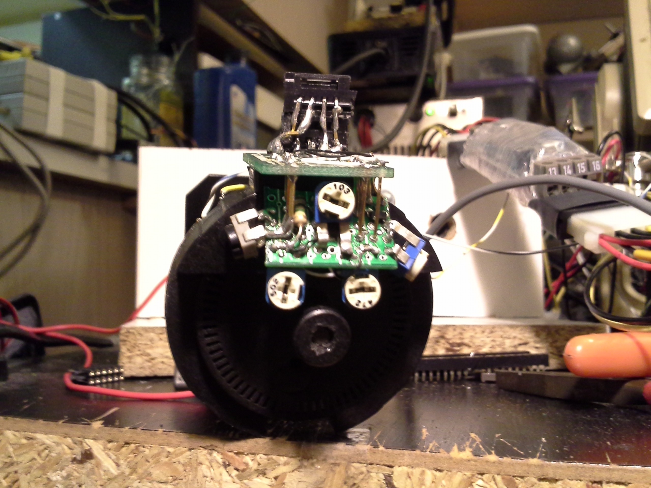
    I hacked the encoder attached to my motor to work well at 5V by replacing some resistors with potentiometers. This encoder's circuit... well, it's *simple*; it just has two IR(?) LEDs, two photo-transistors, and four resistors.

    So, when I moved to my "multiAxisHolder" which is now PIC32-based, those resistor-values didn't work at 3.6V. Well, shit, I ain't bouts to hack those resistors again, and plausibly have to do it *again* if I later decide to use it with a 5V system... so:

    This dandy thing is soldered to the original encoder's PCB where the resistors were originally located... (plus a few extra holes I drilled in empty-space).

    Stupid thing took several days to assemble, and couldn't be tested until it was completely assembled and soldered to the original board, so I was *really* cautious with every connection, and it worked right off the bat :)

    It's more than just a bunch of pots. Here we have a 3.0V LDO running the LEDs and photo-transistors. Under the center pot is a comparator running off the source-voltage. The center pot sets the threshold-value for the comparators. The four remaining pots set the values for the phototransistors and LEDs.

    This part's kinda funky. The original circuit had a 330ohm resistor for one LED and a 451ohm 1% resistor hacked-in for the other. It would seem these diodes have differing brightness?! Or maybe they're not perfectly-aligned or something... Anyways, it's handy having pots for all these things as I've been doing some experimenting. I'll come back to that.

    The new board and potentiometers *just* fit inside the encoder's housing when assembled, which is why it's so... 3-dimensional (yes, it's mounted at about a 70degree angle). It's *cram-packed* both top and bottom.


    So, now, it will run off 5V down to 3.2V, give a digital output at that value, and not have to be recalibrated for a different supply-voltage.

    As for experimenting...

    I have some ideas about using the *analog* output from the photo-transistors as a means to increase the resolution. https://hackaday.io/project/9351/log/32010-quadrature-encoders-with-analog-output

    But I haven't started coding that, and I wanted to get this thing running with my current system... So, I included connectors for both digital-output and analog-output. Also, past-experiments with ball-mouse encoders show similarly analog-output... so this should be a pretty versatile and reliable/sturdy testing system for stuff like that if I decide to feed them into, say, the microcontroller's comparator-inputs or even just the schmitt-triggered digital inputs

    With careful adjustment of all four potentiometers, it's possible to get what looks almost like a perfect sine-wave from each channel, running from about 0V to about 2.5V, so... got some 'sperimentin' to do.

    And, yeah, those comparators are doing their jobs quite well, system's back up and running!

    Oh, yeah, I'm running the motor off an audio-amplifier IC... again for the sake of experimenting. https://hackaday.io/project/9351-blogifying-io/log/30930-currently-audio-amp-motor-driver-cnc-machine

  • PPS = Picking Pins Sucks

    Eric Hertz01/14/2016 at 08:06 2 comments

    //PIC32MX370F512H-64TQFP:
    
    // * = 5V Tolerant (? Marked Gray)
    // ! = RF6 Cannot be used as a change-notification! (Table 2, Note 2)
    // % = Pins 13-18 are programming/debugging pins...
    //     See Note below.
    //
    // VDD = V+
    // VSS = GND
    //                                             SDA1
    //                                          SCL1|SCK1
    //           RC13  RD11   RD9   VSS  RC12   RG2 | RF6   RF3
    //        RC14 | RD0 | RD10| RD8 | RC15| VDD | RG3 | RF2 |
    //          |  |  |  |  |  |  |  |  |  |  |  |  |  |  |  |
    //        --------------------------------------------------
    //       | 48 47 46 45 44 43 42 41 40 39 38 37 36 35 34 33  |
    //       |        *  *  *  *  *              *  *  *  *  *  |
    // RD1 --|49                                       !     *32|-- RF5/SCL2
    //       |                                                  |
    // RD2 --|50                                             *31|-- RF4/SDA2
    //       |                                                  |
    // RD3 --|51                                              30|-- RB15
    //       |                                                  |
    // RD4 --|52*                                             29|-- RB14
    //       |                                                  |
    // RD5 --|53*                                             28|-- RB13/TDI
    //       |                                                  |
    // RD6 --|54*                                             27|-- RB12/TCK
    //       |                                                  |
    // RD7 --|55*                                             26|-- VDD
    //       |                                                  |
    //VCAP --|56                                              25|-- VSS
    //       |                                                  |
    // VDD --|57                                              24|-- RB11/TDO
    //       |                                                  |
    // RF0 --|58*                                             23|-- RB10/TMS
    //       |                                                  |
    // RF1 --|59*                                             22|-- RB9
    //       |                                                  |
    // RE0 --|60*                                             21|-- RB8
    //       |                                                  |
    // RE1 --|61*                                             20|-- AVSS
    //       |                                                  |
    // RE2 --|62                                              19|-- AVDD
    //       |                                                  |
    // RE3 --|63*                                            %18|-- RB7
    //       |                                                  |
    // RE4 --|64                  *                %  %  %  %%17|-- RB6
    //       \  1  2  3  4  5  6  7  8  9 10 11 12 13 14 15 16  |
    //        \-------------------------------------------------
    //          |  |  |  |  |  |  |  |  |  |  |  |  |  |  |  |
    //          | RE6 | RG6 | RG8 | RG9 | VDD | RB4 | RB2 | RB0
    //         RE5   RE7 | RG7  /MCLR  VSS   RB5   RB3   RB1
    //                  SCK2
    //
    //NOTE: 
    //  I2C is NOT remappable
    //      THESE ARE ALL 5V Tolerant
    //       SDA1 = 36 RG3
    //       SCL1 = 37 RG2
    //       SDA2 = 31 RF4
    //       SCL2 = 32 RF5
    //  SPI Clock Pins are NOT remappable
    //       SCK1 = 35 RF6 (5V Tolerant)
    //       SCK2 = 4 RG6
    //  Programming/Debugging pins
    //   These *should* be usable, but I've had some difficulty in the past
    //   PGED/C#
    //       PGED1/C1 = 16/15
    //       PGED2/C2 = 18/17
    //       PGED3/C3 = 13/14
    //
    //1  AN22/RPE5/PMD5/RE5                           33 RPF3/RF3
    //2  AN23/PMD6/RE6                                34 RPF2/RF2
    //3  AN27/PMD7/RE7                                35 RPF6/SCK1/INT0/RF6
    //4  AN16/C1IND/RPG6/SCK2/PMA5/RG6                36 SDA1/RG3
    //5  AN17/C1INC/RPG7/PMA4/RG7                     37 SCL1/RG2
    //6  AN18/C2IND/RPG8/PMA3/RG8                     38 VDD 
    //7  MCLR                                         39 OSC1/CLKI/RC12
    //8  AN19/C2INC/RPG9/PMA2/RG9                     40 OSC2/CLKO/RC15
    //9  VSS                                          41 VSS 
    //10 VDD                                          42 RPD8/RTCC/RD8
    //11 AN5/C1INA/RPB5/RB5                           43 RPD9/RD9
    //12 AN4/C1INB/RB4                                44 RPD10/PMCS2/RD10
    //13 PGED3/AN3/C2INA/RPB3/RB3                     45 RPD11/PMCS1/RD11
    //14 PGEC3/AN2/C2INB/RPB2/CTED13/RB2              46 RPD0/RD0
    //15 PGEC1/VREF-/CVREF-/AN1/RPB1/CTED12/RB1       47 SOSCI/RPC13/RC13
    //16 PGED1/VREF+/CVREF+/AN0/RPB0/PMA6/RB0         48 SOSCO/RPC14/T1CK/RC14
    //17 PGEC2/AN6/RPB6/RB6                           49 AN24/RPD1/RD1
    //18 PGED2/AN7/RPB7/CTED3/RB7                     50 AN25/RPD2/RD2
    //19 AVDD                                         51 AN26/RPD3/RD3
    //20 AVSS                                         52 RPD4/PMWR/RD4
    //21 AN8/RPB8/CTED10/RB8                          53 RPD5/PMRD/RD5
    //22 AN9/RPB9/CTED4/PMA7/RB9                      54 RD6
    //23 TMS/CVREFOUT/AN10/RPB10/CTED11/PMA13/RB10    55 RD7
    //24 TDO/AN11/PMA12/RB11                          56 VCAP
    //25 VSS                                          57 VDD 
    //26 VDD                                          58 RPF0/RF0
    //27 TCK/AN12/PMA11/RB12                          59 RPF1/RF1
    //28 TDI/AN13/PMA10/RB13                          60 PMD0/RE0
    //29 AN14/RPB14/CTED5/PMA1/RB14                   61 PMD1/RE1
    //30 AN15/RPB15/OCFB/CTED6/PMA0/RB15              62 AN20/PMD2/RE2
    //31 RPF4/SDA2/PMA9/RF4                           63 RPE3/CTPLS/PMD3/RE3
    //32 RPF5/SCL2/PMA8/RF5                           64 AN21/PMD4/RE4
    //
    // 5V Tolerant:
    //    7  /MCLR
    //    31 RF4
    //    32 RF5
    //    33 RF3
    //    34 RF2
    //    35 RF6
    //    36 RG3
    //    37 RG2
    //    42 RD8
    //    43 RD9
    //    44 RD10
    //    45 RD11
    //    46 RD0
    //    52 RD4
    //    53 RD5
    //    54 RD6
    //    55 RD7
    //    58 RF0
    //    59 RF1
    //    60 RE0
    //    61 RE1
    //    63 RE3
    
    //    7  /MCLR
    //    46 RD0
    //    52 RD4   \
    //    53 RD5   |
    //    54 RD6   |
    //    55 RD7   |  8bits
    //    42 RD8   |
    //    43 RD9   |
    //    44 RD10  |
    //    45 RD11  /
    //    60 RE0
    //    61 RE1
    //    63 RE3
    //    58 RF0   \
    //    59 RF1   |
    //    34 RF2   |
    //    33 RF3   |  7bits
    //    31 RF4   |   (SDA2 I2C)
    //    32 RF5   |   (SCL2 I2C)
    //    35 RF6   /   (SCK1 SPI)
    //    37 RG2       (SCL1 I2C)
    //    36 RG3       (SDA1 I2C)
    
    
    // PWM Pins:
    //  OC1, OC2:
    // RD1   OC1,OC2
    // RG9   OC1,OC2
    // RB14  OC1,OC2
    // RD0   OC1,OC2
    // RD8   OC1,OC2
    // RB6   OC1,OC2
    // RD5   OC1,OC2
    // RF3   OC1,OC2  *
    // RF6   OC1,OC2
    // RF2   OC1,OC2
    //  OC3:
    // RD2   OC3
    // RG8   OC3
    // RF4   OC3
    // RD10  OC3
    // RF1   OC3
    // RB9   OC3
    // RB10  OC3
    // RC14  OC3
    // RB5   OC3
    //  OC4:
    // RD3   OC4
    // RG7   OC4
    // RF5   OC4
    // RD11  OC4
    // RF0   OC4
    // RB1   OC4
    // RE5   OC4
    // RC13  OC4
    // RB3   OC4
    // RF3   OC4      *
    //  OC5:
    // RD9   OC5
    // RG6   OC5
    // RB8   OC5
    // RB15  OC5
    // RD4   OC5
    // RB0   OC5
    // RE3   OC5
    // RB7   OC5
    //...
    Read more »

  • More Motion Experiments, Oil=Good, Chickens, etc.

    Eric Hertz12/29/2015 at 10:13 2 comments

    The latest test is a loop something like:

    Travel 8000 steps forward

    Travel 8000 steps backward

    double the speed and repeat (until the max-speed)

    The 'oneAxisHolder' takes in a single byte at a time on its UART, representing -128 to 127 *steps* away from where it's at currently. So "speed" is entirely a factor of the transmitter, in this case a bash-script on my computer. I set it to send one byte at a time, at, as I recall, 0.03 seconds (which is *just about* the limit at 4800baud). There's some slight stuttering, as mentioned in the previous log, which I *believe* to be due to buffering on the computer-side... I've run into this one before, and never noticed it when controlled by a dedicated [micro]controller.

    Adding oil to the screw-shaft was *definitely* an improvement... At the end of the last log/video you can hear some scraping. And, at high-speed the binding was so great at times that the motor would even stall (?!). That binding, grinding, scraping, and stalling has all but vanished even at high speeds with just a little motor oil.

    Now it "buckocks" like a chicken... Interesting that hadn't been noticeable before.

    On the closer rail, the glider is firmly physically attached to the carriage. At the farther rail, the glider "floats" in a little slot on the carriage (rather'n a hole). I think they do this so that the two rails don't need to be perfectly parallel (which was certainly appreciated during assembly!). The end-result, it seems, is that the carriage rides along the stationary floating "glider" until it hits an end-stop that causes the glider to move with the carriage. Thus... "Buckock!"

    I'm hesitant to add oil to that part, but maybe unjustifiably so. The thing is, the gliders appear to be fiberglass... And for some reason that to me means somewhat permeable, which I suppose could mean expansion, which could be bad considering as it stands the gliders are *very* tight on the rails. This is all hypothesizing, on my part... Wisdom, anyone?

    And, again, the 'oneAxisHolder' is quite handy for experiments like these, but doesn't quite suit [one of] my end-goal[s], which requires two motor/encoder pairs, one of which is to be used as a hand-lever.

    So, on to designing the next circuit... plausibly for two axes... And doing-so has gotten side-tracked again into the [plausibly] "Ridiculous" realm... I'm experimenting, again, with using audio-amplifier chips to drive my motors. https://hackaday.io/project/8348-random-ridiculosities-and-experiments/log/29597-audio-amp-motor-driver-class-b-this-time (If you're looking for really cheap high-current audio-amps that could plausibly be *each* used as *four* motor-drivers, check that link, quick... Sale Ending TODAY!)

  • Days of fail, and finally it moves!

    Eric Hertz12/26/2015 at 13:23 1 comment

    Alright, so it was stupid, stupid, stupid of me...

    Apparently at some point (yes I remember doing this, no I don't remember *leaving* it this way) I modified the script that outputs the commands to the motor-driver... To: instead of outputting raw binary for positional-changes, instead output user-friendly hex-values. I just wanted to verify the conversion was working properly (this is a bash script). Brilliant, right? Wrong. Yeah, don't forget to comment-out that line when you're using redirection ('>') for the script's output to the serial-port!

    So, simply, the motor-driver takes a single-byte value, -128 to 127, which tells it how many steps to take... And of course the "user-friendly" version was outputting several ASCII bytes... which, of course, are *positive*. Thus, the motor was going both *positive* regardless of what value I gave it, AND went *really far* each time (a sum of all the bytes transmitted).

    Duh. No more redirection of binary values. Use two separate output-streams, one for the terminal, one for the serial-port. This realization came *long* after looking into all sorts of other things... including some amount of certainty that the uC's R/C oscillator was drifting too much for my 4800baud serial transmission... (seriously?!). Well, my de-facto for all projects is to have a fading LED that cycles at a rate of 8 seconds... I measured 7.3. That's pretty far off, so completely reasonable it might've been responsible. So I popped the ol' scope on the serial signals and realized that my new USB->Serial converter is 3.3V, and I'd already determined that my uC's VIH-min is 3.5V... so... well it did work a few days ago, but probably isn't particularly reliable. But the data-timing...? Looks pretty durn accurate to me, certainly not a full bit off (which would cause the "stop" bit to be detected as a '1' in the most-significant data-bit, which might've explained the large motion... except that the MSB is the *sign* so... I dunno.). And of course, that's when I noticed it was transmitting *several* bytes at a time...

    Back to the old USB->Serial converter, also. At least I know its inputs are 5V-tolerant (I added that long ago).

    Oh, right, and the transistor-biasing issue... @K.C. Lee to the rescue again... I got all hung-up on trying to figure out a versatile solution, but wasn't getting anywhere. He suggests: just replace them dang 3.3k pull-down resistors with something higher, dagnabbit! So, I needed to see this thing moving again, dagnabbit! I cut them dang 3.3ks out of the circuit and soldered on some 20k potentiometers (and removed my transistor-buffer circuit entirely).

    So, some observations: With the mouse-encoders I'd worked with previously, there seems to be some correlation with the pull-resistor values and the *speed* the transistors can respond. A higher value resistor, if I remember correctly, results in *slower* response. My theory being somewhat like that of the difference between ECL and TTL... ECL is faster than TTL because it keeps the transistors AWAY FROM saturation (ECL uses the linear range), Switching out of saturation takes time. Anyways, that's not (yet?) a problem here, since the motor's running *much slower* than the really-high-speed motors I had connected to the mouse-encoders.

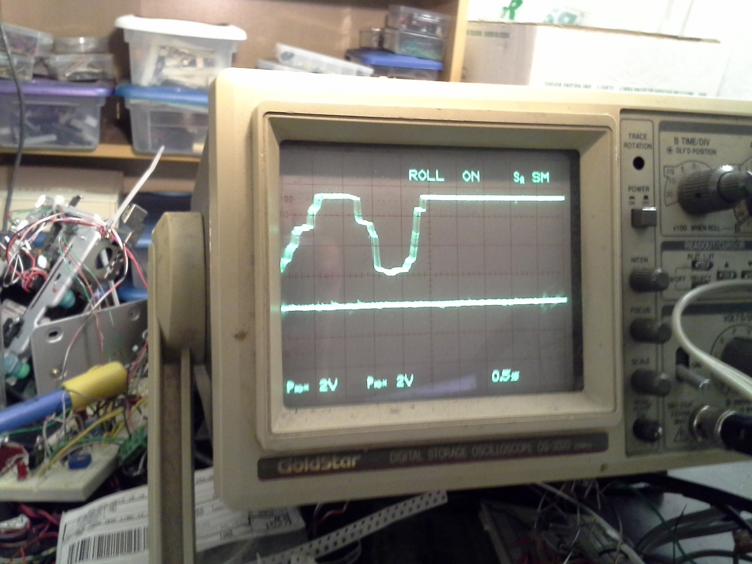
    Increasing the resistance essentially increases the "amplification" of the signal... so whereas before it was somewhat sinusoidal, now it's closer to digital... rather, it's like an amplifier hitting its (upper) rail... There's still analog changes as the motor is rotated slowly between slot and shade(?), and it also appears to remain sinusoidal-ish at the lower-rail.

    Thankfully, my microcontroller has Schmitt-triggers, and the system's now definitely within the VIHmin and VILmax ranges, so it seems alright. Though, I'm not certain the "threshold" is particularly well-defined... Imagine a sine-wave amplified *a lot*, with its bottom touching 0V and hitting the upper rail (5V) long before the sine-wave reaches its zero-crossing......

    Read more »

  • First Axis Encoder

    Eric Hertz12/23/2015 at 16:14 3 comments

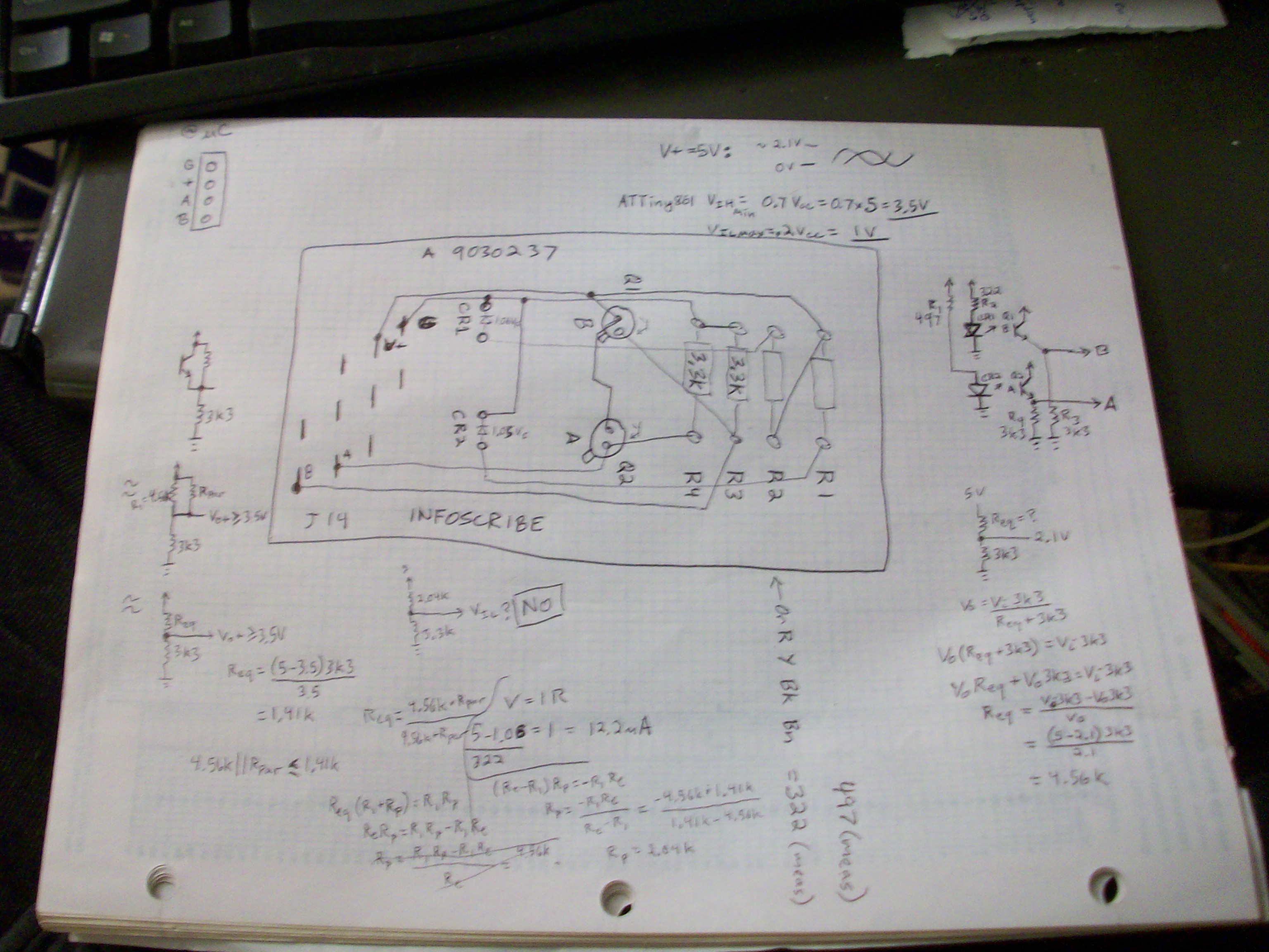
    Yesterday: FINALLY figured out the pinout of this encoder's circuit... Apparently it's just two photodiodes, two photo-transistors, and four resistors. Even most computer-mice I've seen have more sophisticated circuits, usually involving two resistors for each transistor... and some, I think, even tied the transistor's output to the diode, as a sort of amplifier feedback-loop. The signals coming out are usually somewhat sinusoidal, requiring a comparator at the receiving end... or at the very-least a forgiving Schmitt-trigger. Most motor-mounted encoders I've seen, even the ones made of discrete components like this one, have comparators or some other sort of digital-output-driver at the transmitting-end... would certainly help with noise-immunity... This motor's marked 1982, so maybe they were using analog power-control rather'n PWM, then switching noise wouldn't be as big a concern...

    Regardless, the output swings from 0V to 2.1V with a 5V source. My microcontroller's digital inputs (despite schmitt-triggers) are rated for 3.5V VIH-min. So, not surprised it didn't detect any movement with my first attempt.

    All that math was to determine whether I could get away with putting a pull-up resistor on the outputs to get it in range of a digital input... I calculated (based on the maximum output voltage) that the phototransistors look like a 4.56k resistor when fully-illuminated. So I'd need a ~2k pull-up resistor (in parallel to the transistor) to achieve 3.5V. Unfortunately, that would mean that the completely-dark case looks like a voltage-divider with a 2k upper-resistor and a 3.3k lower-resistor, so the output-voltage would be too high for VIL-Max = 1V.

    (Much later note, per a comment from @K.C. Lee... How is it I didn't think of running the encoder off 5V, and my microcontroller off 3.3?).

    I could modify this encoder's circuit-board pretty easily, there's plenty of space for hacking. Then I could've probably had it running in a couple hours. But I got sidetracked contemplating more-versatile options...

    I've been using computer-mouse-encoders in projects over the past year-ish... those are similar in output to this. And I've got a few other encoders of questionable-output. So... what would be more versatile...?

    Analog-comparators happened to be an easy-choice for my PIC32-based circuit, choosing a low threshold voltage. But, what if the transistors were low-side...? Then I'd have to change it to a higher threshold-voltage... either software would have to change, or there'd need to be a potentiometer added... Besides that, I only built that on a solderless-breadboard, and now entropy is setting in.

    I came across my AVR-based "oneAxisHolder" (soldered) circuit from long ago, while cleaning the workbench... I used this in some early experiments in the past year or so, then switched over to the PIC32. The nice thing about the oneAxisHolder is that it's soldered-up and so far has been basically plug-and-play... RS-232 input to control the position, an encoder input, and a motor output... The PIC32 runs almost the exact same software, but I've improved it a little bit to handle things like using comparator-inputs. That code is *mostly* architecture-agnostic, so porting it back to the AVR would be pretty simple... but the oneAxisHolder's encoder inputs aren't soldered to Analog-comparator pins... And technically the AVR only has a single analog-comparator (though switching its inputs is possible, that wouldn't allow for using interrupts...)

    But, they are soldered to pins that have ADCs... so that's a contemplation...

    This has been another long-running consideration... With encoders like these, where the output is analog, rather'n digital, (which just happens to be commonly-associated with low-resolution encoders, in my collection) it might be possible to increase the position-resolution by using the analog values and ADCs... That's something that might be difficult, and not exactly in my mind-set at the moment. Thing is, of course,...

    Read more »

View all 6 project logs

Enjoy this project?

Share

Discussions

James Newton wrote 12/23/2015 at 01:01 point

Looking forward to seeing it move.

  Are you sure? yes | no

Eric Hertz wrote 12/23/2015 at 07:56 point

Cool, Thanks! ME TOO.

Tonight: FINALLY figuring out the pinout of this encoder's circuit... Apparently it's just two photodiodes, two photo-transistors, and four resistors. Even most computer-mice I've seen have more sophisticated circuits, usually involving two resistors for each transistor... and some, I think, even tied the transistor's output to the diode, as a sort of amplifier feedback-loop. The signals coming out are usually somewhat sinusoidal, requiring a comparator at the receiving end... or at the very-least a forgiving Schmitt-trigger. Most motor-mounted encoders I've seen, even the ones made of discrete components like this one, have comparators at the transmitting-end... would certainly help with noise-immunity... This motor's marked 1982, so maybe they were using analog power-control rather'n PWM, and switching noise wasn't as big a concern... And/Or, maybe, this encoder-disk's (comparatively) *huge* notches result in full-on/full-off output. 

So this might not connect *directly* to a digital I/O... we'll see in a couple minutes.

I just found my "oneAxisHolder" circuit from long ago, while cleaning the workbench... so if I don't need comparators I could've probably wired this thing up and had it moving in the time it took me to write this. Wee procrastination!

  Are you sure? yes | no

Eric Hertz wrote 12/23/2015 at 09:09 point

...rightfully-procrastinated... 0V to 2V output-swing = apparently not high enough to be detected as high. Got some circuitting and/or softwaring to do.

  Are you sure? yes | no

K.C. Lee wrote 12/23/2015 at 10:36 point

- cover the sensors from ambient light?
- add external pull up resistor to your power rail at the receiving end?
- 2V might work for 3.3V CMOS type logic input?  It is a bit marginal for 2/3 Vcc, but probably would work.

  Are you sure? yes | no

Eric Hertz wrote 12/23/2015 at 16:51 point

@K.C. Lee, good suggestions... somehow I didn't see using 5V for the encoders and 3.3V for the AVR as a solution. Duh. That would've been easy. 

Wound up using a TTL-serial buffer/inverter circuit I made a while back as a level-shifter... I'll log it soonish. The pull-up resistor solution was a no-go, the necessary value for a 3.5V high would result in a 2V "low"

  Are you sure? yes | no

Does this project spark your interest?

Become a member to follow this project and never miss any updates