 Laetitia BEL
The calculation and data processing is handled by the PCB TOP electronic card.
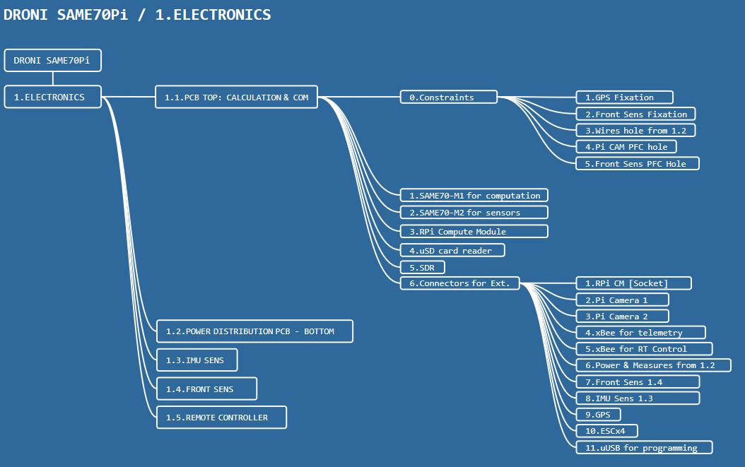
1.1.0.Constraints
The TOP PCB shall have
- the GPS fixation holes
- the front sens fixation holes (2x holes)
- the wires holes that link the power distribution
We need to have flexibility to position the Pi Cams either in the bottom or the front. The TOP PCB shall allow passing the PFC cable of the Pi Cam through holes.
The TOP PCB shall be powerable using a uUSB for tests. It will be heavy if we require the powering from the BOTTOM PCB, specially during debug phase of the microcontrollers.
The TOP PCB shall have the possibility to add connectors for each UART for debuging.
The same thing with the front sens card, the link between the front sent and the TOP PCB is done with a cable. The TOP PCB shall have a hole to allow passing it.
1.1.1.SAME70-M1
In charge of controlling the motors, stabilization, directional adjustment.
The critical calculations (stabilization, motor control,...) is done by the SAME70-M1 uC.
It gets directly the IMU data from the IMU SENS.
It communicates the secondary uC SAME70-M2 to get instructions (GPS data, initialization & arming,...etc) through a UART interface.
It isn't not interfaced with the FRONT SENS.
It is programmed using a uUSB on the TOP PCB.
It is interfaced with the xBee-M1 in charge of the control (manual navigation and critical instructions).
1.1.2.SAME70-M2
In charge of telemetry data, navigation instruction.
The IMU data is retrieved from the SAME70-M1 (not directly from the IMU SENS).
It gets the data from the GPS through UART. Most of the GPS are UART driven.
It communicates with the RPi CM using UART.
It is interface with the FRONT SENS.
It gets the current of the LiPo from the BOTTOM PCB.
It gets the voltage of each cell of the LiPo from the BOTTOM PCB.
It is programmed using a uUSB on the TOP PCB.
It is interfaced with the xBee-M2 in charge of the telemetry.
1.1.3.Raspberry Pi Compute Module
The RPi CM is in charge of heavy data processing, imaging, navigation plan,...etc. It get the processed data from the GPS, IMU, Sensors,...etc from the SAE70-M2.
It is interfaced with the SAME70-M2 using UART.
it is interfaced with the SDR circuit using SPI + selection.
I checked the circuits that uses a SDR, most of them are SPI driven, I suppose mostly we will use the SPI too.
it is interfaced with the uSD card using SPI + selection.
I add a USB-A to the TOP PCB for peripheral of the compute module. Am thinking about a WiFi dongle.

1.1.4.uSD Card
It is used to store user defined data by the RPi CM.
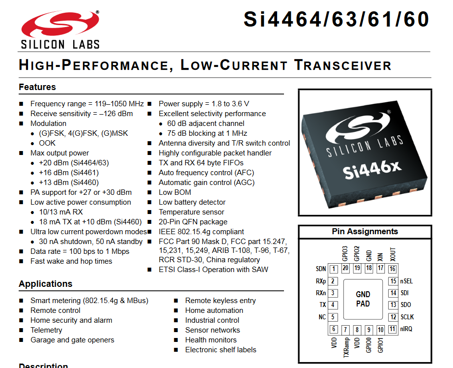
1.1.5.SDR
The idea is the have additionally a software defined radio embedded in the TOP PCB. I played with the Si4464, I thought it might be interesting to add it.
Since the SAME70-M1 and M2 both have xBee to talk with, it might be interesting if the RPi CM has also it's radio.
1.1.6.Connectors for external interfaces
The TOP PCB shall provide connectors and sockets for the following modules:
- the Raspberry Pi Compute Module
- RPi Cameras
- xBee modules
- BOTTOM PCB
- FRONT SENS
- IMU SENS
- GPS
- ESC (PWM)
- uUSBs for programming
Discussions
Become a Hackaday.io Member
Create an account to leave a comment. Already have an account? Log In.