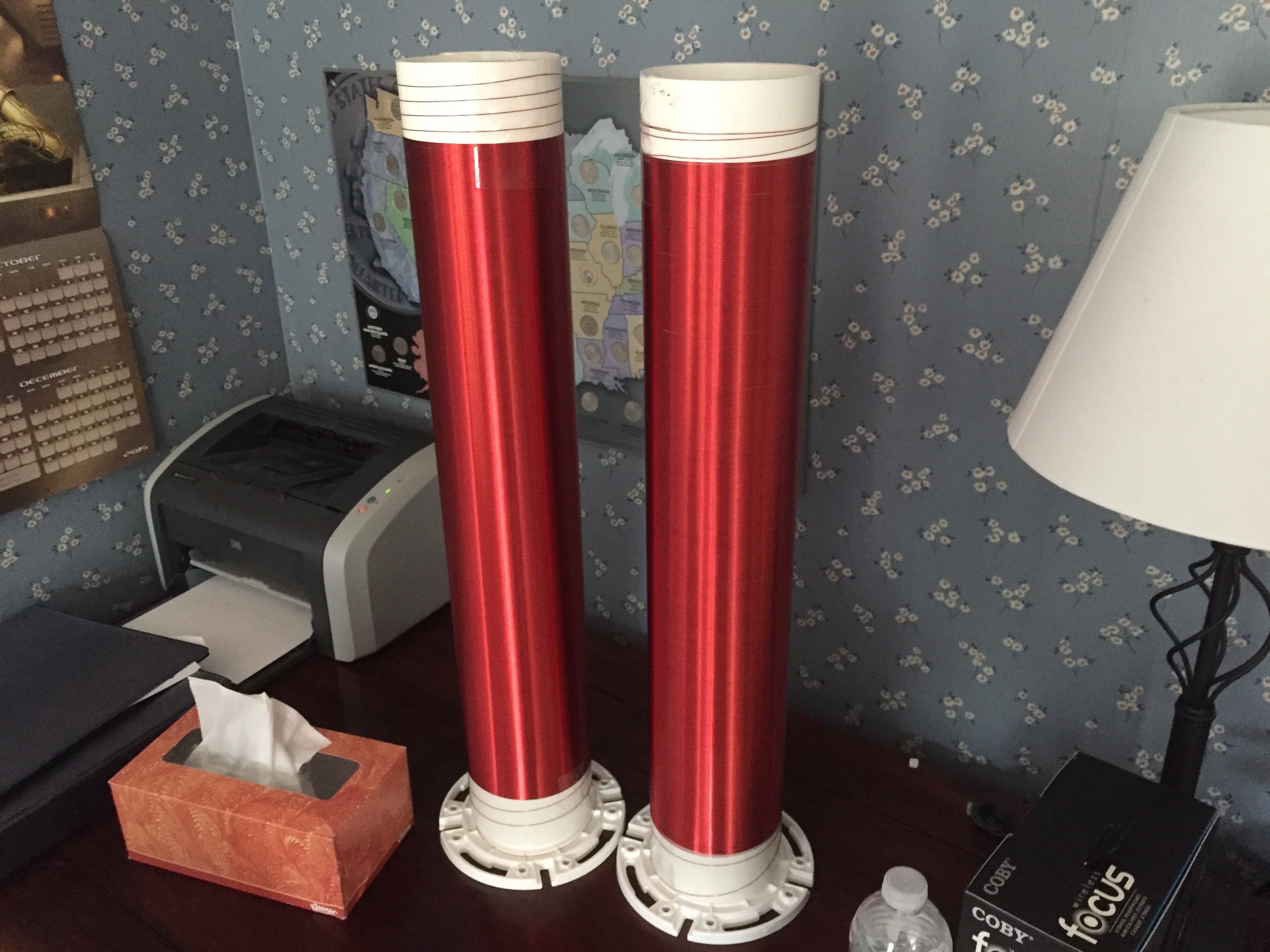
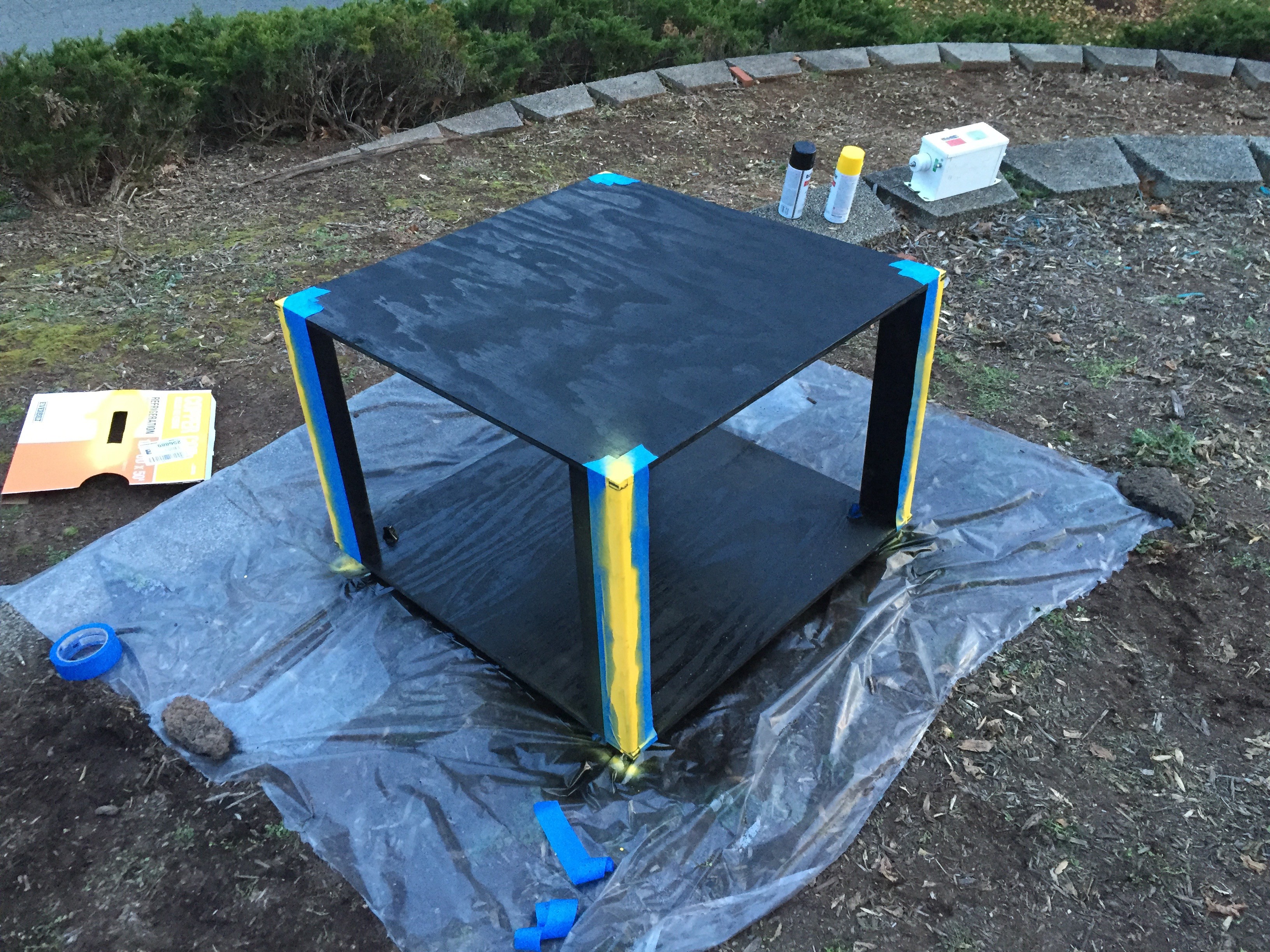
• Strike Ring (Primary Protection)

    Leo Mahdessian07/19/2016 at 03:22 0 comments

    Not much to say about the strike ring. It was constructed from 1/4 inch copper water pipe with 4 elbow joints that were sweated together. It was directly grounded to the bottom of the secondary coil. Mounted it to the base using wood blocks to elevate it above the primary coil.

    The wood blocks had a piece of PVC pipe glued to the top that the strike ring could snap into. The photo below shows the sweated strike ring.

    The photo below shows the mounting blocks before the strike ring was installed.

  • Secondary Coil

    Leo Mahdessian07/19/2016 at 03:07 0 comments

    The secondary coil on our Tesla Coil was built around a 4.5 inch PVC form and was 22 inches of coil with a total form height of 26 inches. A few things to keep in mind when choosing a form: 1) make sure the form you are using contains no metal. Some PVC pipe contains metal to help it be found after being buried in the ground. 2) In our case we bought 4 inch PVC pipe. 4 inches was the measurement of the inner diameter of the pipe, not the outer, so always keep that in mind when designing a secondary coil. The wire we used was 24 AWG polyurethane coated magnet wire. We used about 1000 feet of wire to wind 22 inches of our coil. We also drilled two small holes in the pipe at the top and bottom to run the wire through to make its connections to either ground (bottom) and to the torrid (top). To wind the coil we strapped the PVC pipe into a lathe and then manually spun the PVC pipe while guiding the wire to make sure it stayed taught and there was no gaps. In retrospect, It would have made more sense to run the lathe on its lowest speed setting rather then turning the pipe by hand.

    Below is a photo of the finished coils. There are two coils because originally we planned on building a transmitting and receiving coil but later scrapped the idea after deciding that our knowledge of high frequency wireless power was not sufficient enough to use that idea.

    We used 4 inch toilet flanges to mount the secondary coil to the base inside of the primary coil. The slots in the flange lined up perfectly with out primary coil supports.

  • Primary Coil Constuction

    Leo Mahdessian01/14/2016 at 15:16 0 comments

    The primary coil consists of 50' of 1/4in copper pipe that is spiraled outward from the secondary coil mounting point. There is 14 turns of the piping. To hold the copper pipe in place, four acrylic mounts were laser cut and glued to the base. The acrylic is 1/4in thickness. Here is a photo of the laser cutter: (The laser cutter was located at Nova-Labs in northern Virginia, check out their website here: Nova-Labs.org)

    Here is a photo of one of the mounts half done:

    After glueing the mounts down, we realized that the slots were deep enough for the copper pipe to stay in the desired shape. Painstakingly, we drilled each slot deeper with a drill press, and used a bandsaw to remove any excess acrylic. Afterwards, we glued the mounts back down to the base. Then we took the copper tubing and spiraled it into each slot. The one advantage to drilling the slots deeper was the pipe snapped into the mounts. After all the pipe was spiraled, we used a 1/4" piece of wood to make sure the spacing between each turn was 1/4". Then we used a piece of scrap wood to make sure the height of each turn was equal. After, we used hot glue to secure the copper to the mounts. (I would recommend to use 8 mounts instead of 4 like we did. It makes the spacing between the turns more equal.)

    Here is a photo of the completed primary:

  • Control System

    Leo Mahdessian01/13/2016 at 14:40 0 comments

    Control Panel:

    To control the tesla coil, we built a control panel to allow use to safely operate the coil from a distance. The panel has a emergency stop, key lockout, engage button, alarm button, and fan switch. 120V power enters the box through a 12-Pin connector on the back of the box, it then immediately goes to the emergency stop switch, which is normally closed. From there, the power flows to the key switch and then is distributed to the "fire" switch, alarm switch, and fan switch. The key switch is normally open in the middle position. The fire, alarm, and fan switch are all normally open. The fire switch and alarm switch are both momentary and the fan switch is latching. There is also a voltage/amperage panel mount meter that is tapped of the power after the emergency stop switch.

    Picture of the wiring inside the control box:

    The male end of the 12-Pin connector:

    Eventually, a raspberry pi system to log voltage and amperage data will be implemented.

    Control System:

    On the tesla coil itself, there is a one gang electrical box with a timer installed. Once the power leaves the wall, it goes into the electrical box and then into the timer. Once it leaves the timer, it goes to the control box. After it comes back into the electrical box, it is then distributed to the NST, the fan, and the alarm, respectively. The wire that runs to the control box and back is two electrical cords taped together and also ziptied.

  • Building the Base

    Leo Mahdessian01/12/2016 at 22:55 0 comments

    The tesla coil needs a base that can support the electronics and the coils itself. We built ours out of 2x4 and 1/2" plywood. The base also has 2" castors in each corner of the base for movability. Here is a photo of the sanded, unpainted base:

    Here is a photo of the castors on the bottom:

    Finally, the base was given a coat black spray paint, and yellow accents for the corner. Here is a photo of it being painted:

    4 2x4's are cut to size to provide the vertical supports, and the top plywood is cut to 29 1/2" to provide adiqute space for the primary coil.