 Jeremy
Presentation
It usually takes years to master an instrument, and it takes a lot of time, effort, and practice.
Although it is very difficult to pick the right instrument, learning music the right way can certainly help.
Music can be very theoretical and appear complicated to kids. However, kids usually love to hit things and make noise, sometimes even with a surprisingly very good rhythm and melody, and those two elements are key. It is not a coincidence if most famous music video games consist in pressing the right button at the right time (or hit the right pad at the right time). Showing the notes that need to be played and scrolling them in sync with the music is very intuitive and efficient.
The goal of eXaTutor is to take the idea of rhythm games one step further by turning a rhythm game into a training tool. On the one hand, the user interface will be based on those of video games, on the other hand, data will be collected in order to create training programs tailored to the user's experience. The software will give the user all details about what and how he or she can improve.
How it works
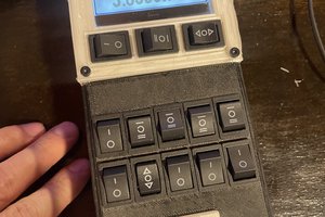
One of the easiest instruments to introduce kids to music seems to be the xylophone. Perhaps because they can hit things, make music, and have fun all at the same time. In that regard, eXaTutor's official version will be a xylophone. Of course, it will remain possible to modify the hardware in order to turn it into any instrument.
The software is what will make eXaTutor great. It will provide a visual way of learning music, teach the good techniques and guide the user. It will adapt itself to ensure the best learning curve possible and find the right balance between practice and fun, in order to keep the user motivated.
Hardware
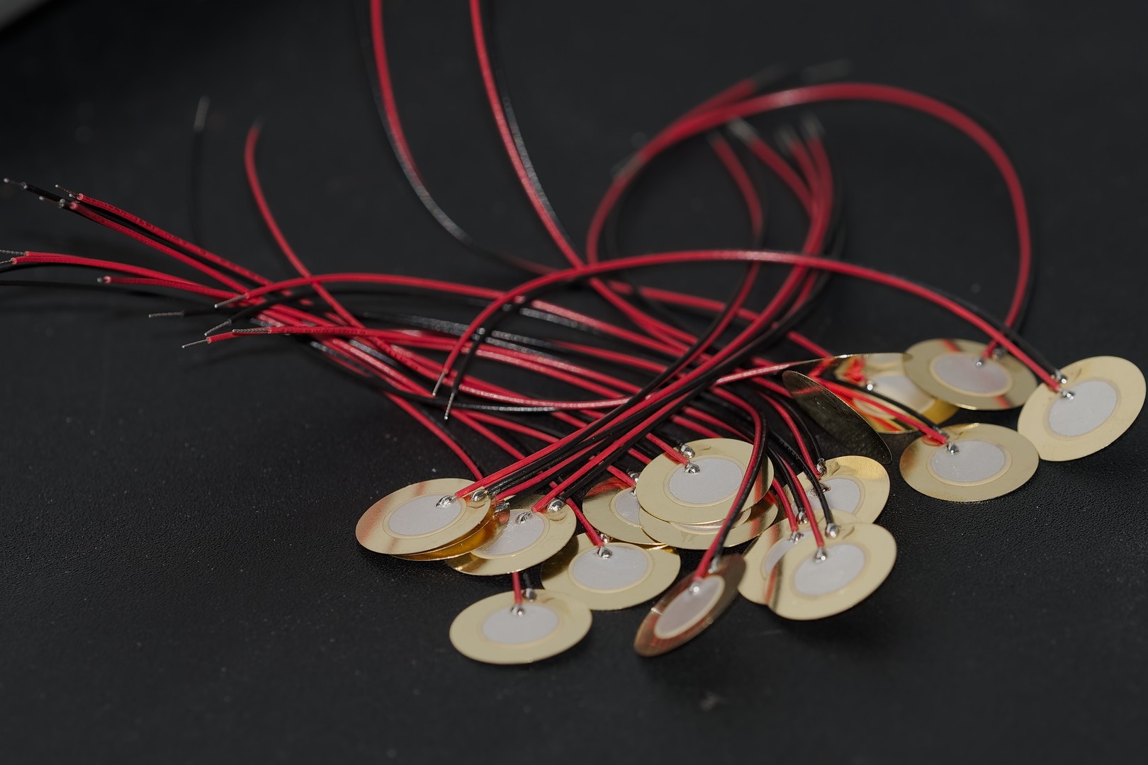
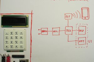
EXatutor uses a Raspberry Pi and its 7" official touchscreen as a user interface. Sensors are connected to an analog to digital converter, which is connected to the Raspberry Pi. As for the system's fabrication, it will be made as easy as possible.
Software
The software is being designed, and will rely on libeXaDrums in order to offer the best performance possible. Gtkmm will be used to program the user interface, and make as user friendly as it can get.
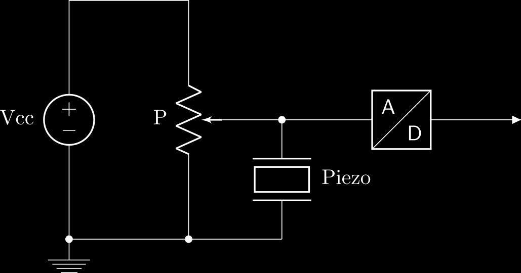 Let's consider a 10k potentiometer. In that case, if we use a 5V power supply, the potentiometer acts as a voltage divider:
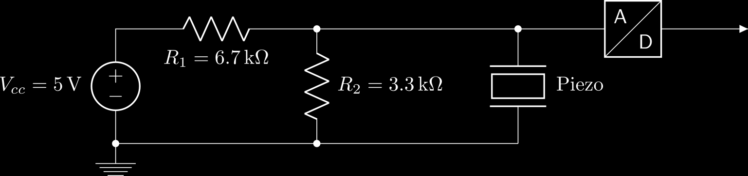
 jaromir.sukuba
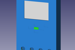
 Karl S
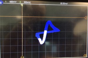
 John Duffy