 Jeremy
In order to read the piezos voltages in real time, we are going to use a RaspIO Analog Zero board. The board uses an MCP3008 analog to digital converter (ADC) that has an input voltage range of 0 to 3.3V.
As a consequence, we need to map the output voltage of each piezo sensor to the 0-3.3V range. There are several ways to do that, but we're wondering here what's the easiest solution. And by the easiest, we mean the solution that requires the less components.
First of all, we need to remember how a piezo sensor works. In short, we could say that a piezo sensor converts a mechanical strain into a voltage. But what happens when this voltage source is connected to a load?
Like any voltage source, a piezo sensor has its limits, and can only deliver so much current when connected to a resistor. When the load is too small, the current going through it becomes too high for the piezo to maintain a high voltage, thus the voltage decreases.
Does that means that connecting a small resistor between the legs of a piezo decreases its output voltage? Yes, but not only: it also modifies its response, but in our case, we will assume that this effect is not a limitation as we only need to detect voltage peaks.
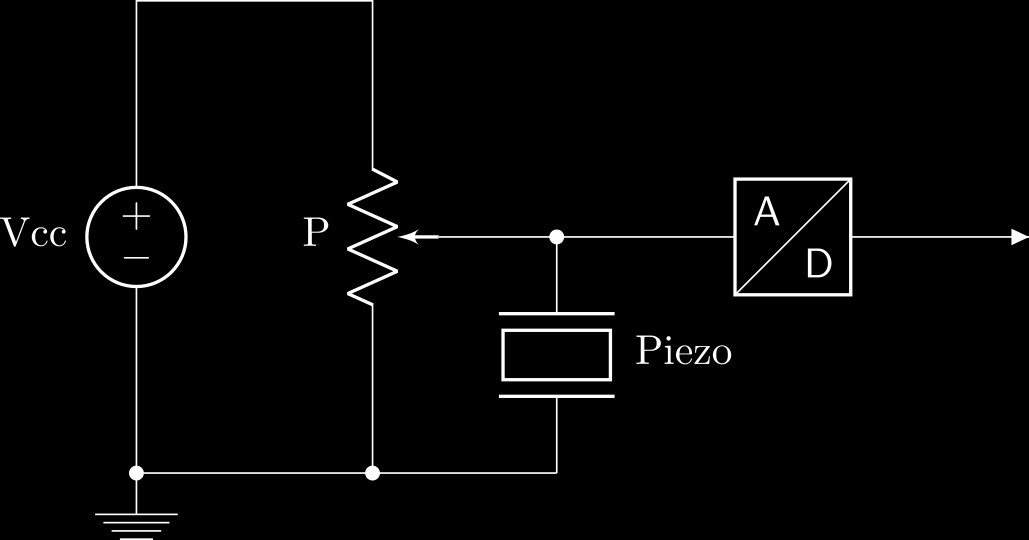
Because the piezo's output voltage undergoes positive and negative peaks, we need to set a resting point of 1.65V (3.3/2 V) to be connected to our ADC. That can be done using a potentiometer, like so:
 Let's consider a 10k potentiometer. In that case, if we use a 5V power supply, the potentiometer acts as a voltage divider:
 Since we know that R1 + R2 = P = 10kΩ, if we want Vout to be 1.65V, we need R2 to be 3.3kΩ:
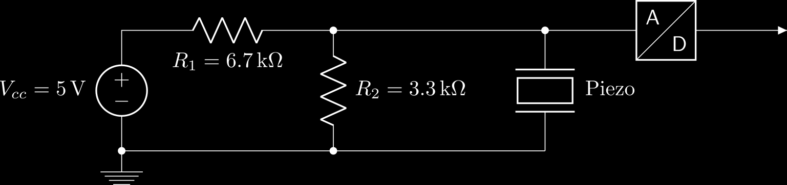
So by using a potentiometer, not only we've managed to set a 1.65VDC input voltage at the input of the ADC, but we've also added a load (R2) in parallel with the piezo. The sensor is thus seeing a resistive load of 3.3kΩ (if we neglect the input impedance of the ADC), which means that its output voltage will be a lot weaker than if it was directly connected to the ADC.
My first experiments show that, under normal conditions, no damping of the piezo is required. But in order to prevent the voltage from going above 3.3V or below 0V, I'm probably going to dampen it a little bit.
Sounds that I'm lucky (or maybe it was all planned), as there is a potentiometer board that has eight 10k potentiometers. I've already bought one, which I found on Mouser (reference 932-MIKROE-316).
Next time we'll see how to use this board to connect our 8 piezos to the MCP3008.
Discussions
Become a Hackaday.io Member
Create an account to leave a comment. Already have an account? Log In.
Did you find the above dampened the piezo output enough? I'm finding it decays slowly and it's difficult to trigger from it.
Are you sure? yes | no