 Arduino Enigma
This log will show how to assemble your own Sinclair Scientific Calculator emulator.
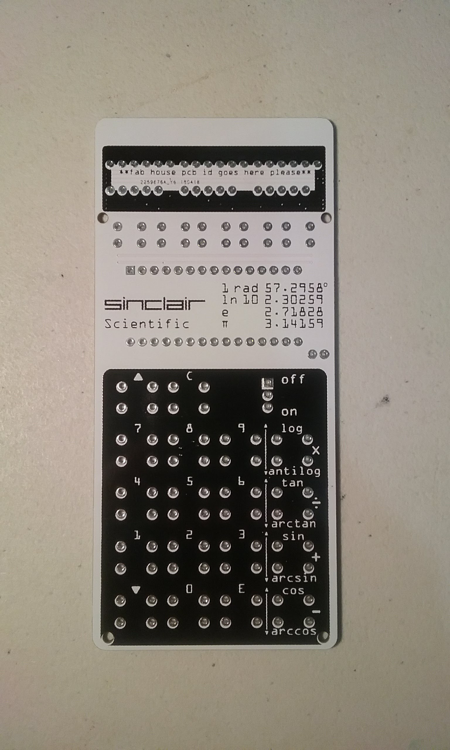
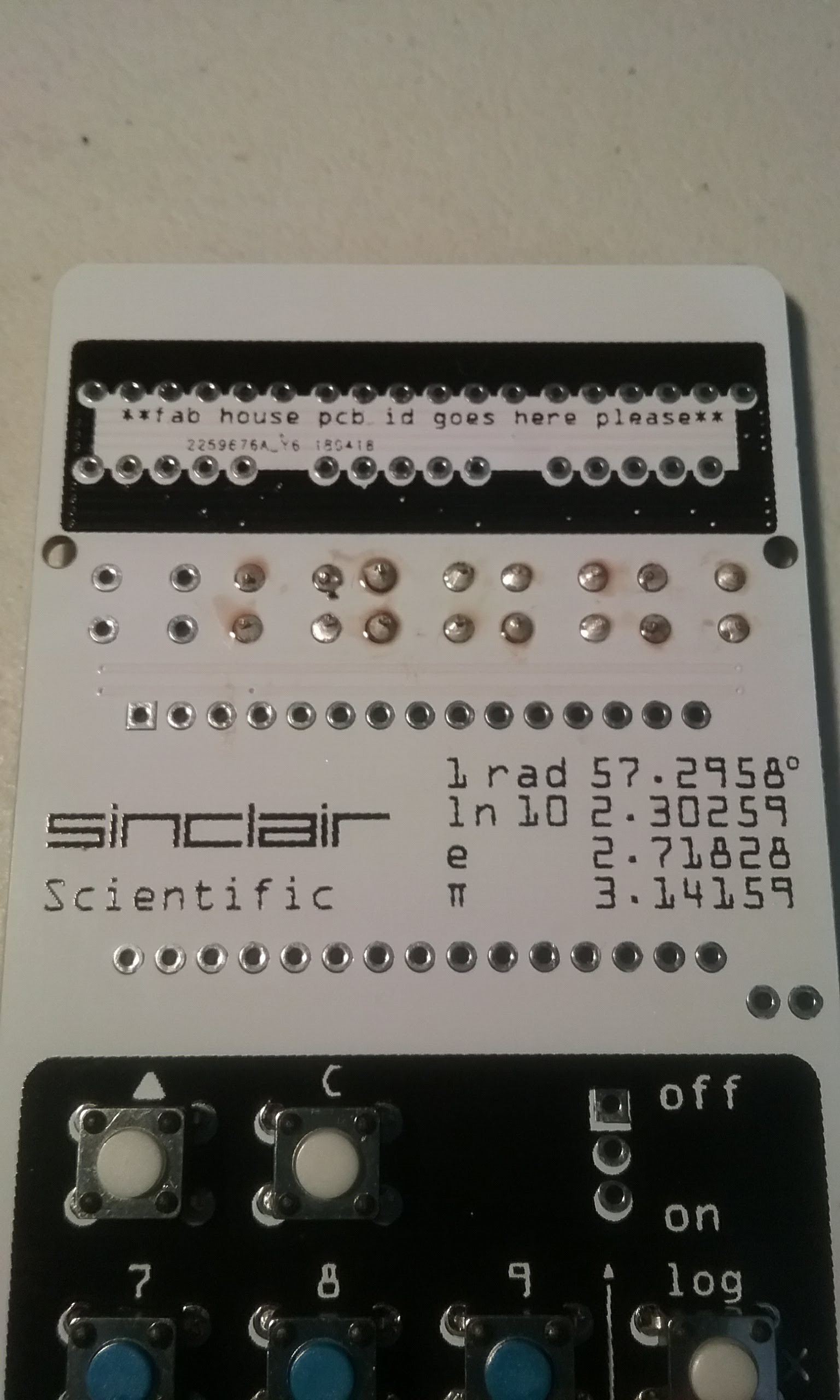
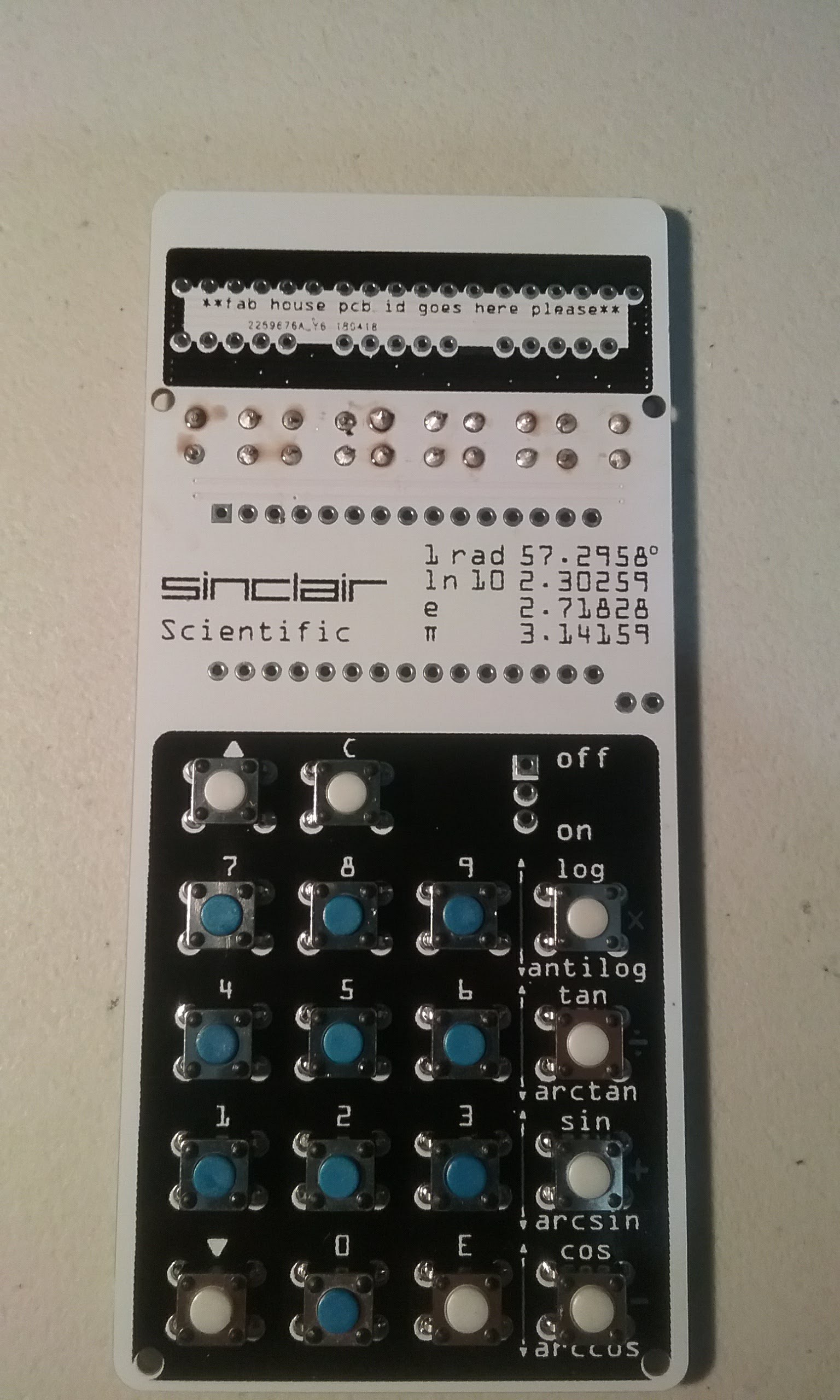
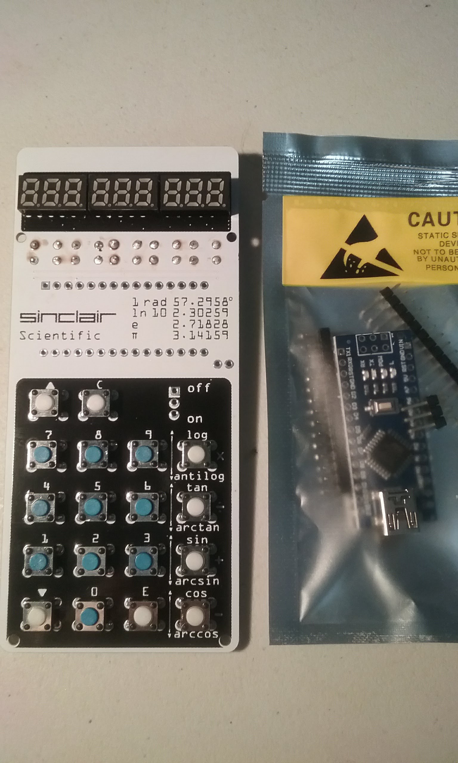
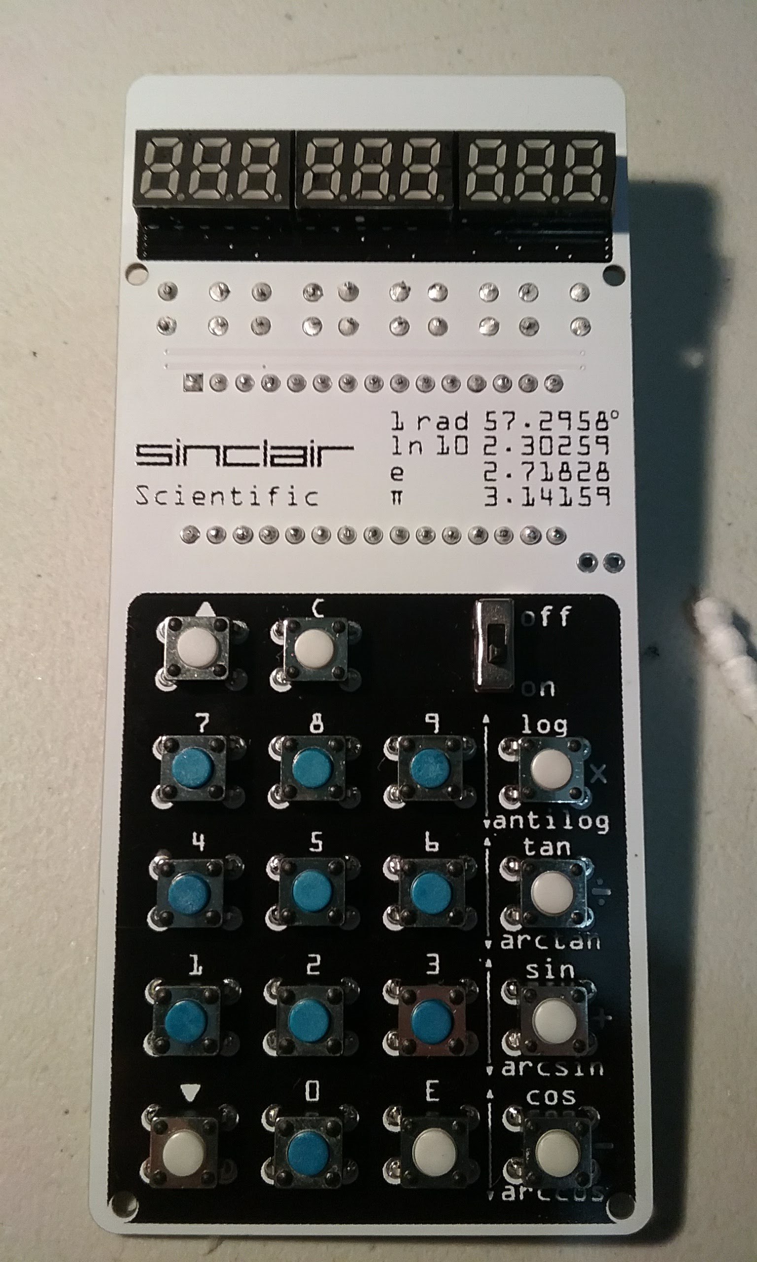
First we start with the blank PCB.
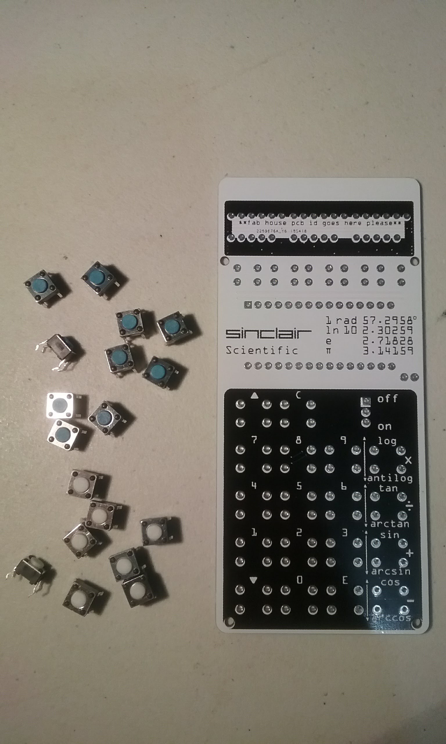
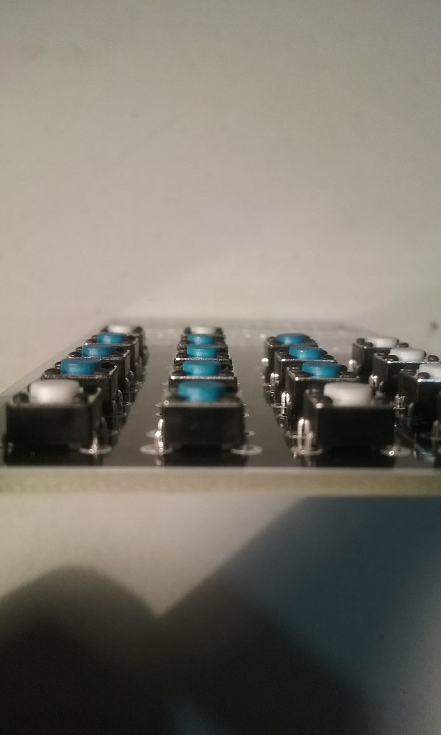
Separate the buttons. You should have 10 blue buttons and 8 white buttons.
---- WARNING!!! ---
If you have purchased a kit, the calculator comes with the buttons and displays installed just to prevent damage during shipping. The blue buttons need to be removed and installed in their correct positions, the number keys.
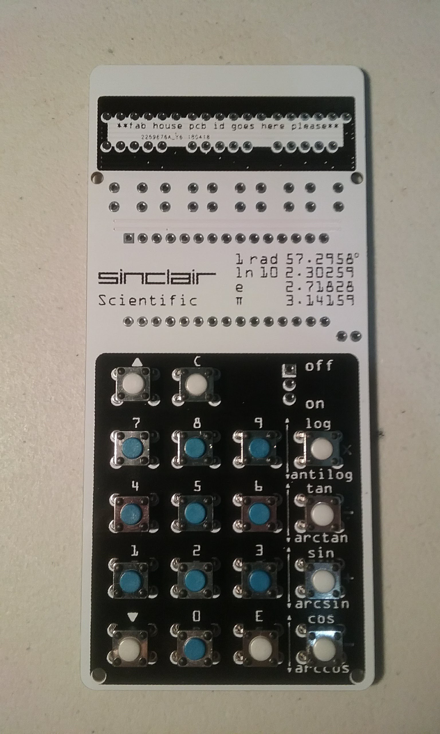
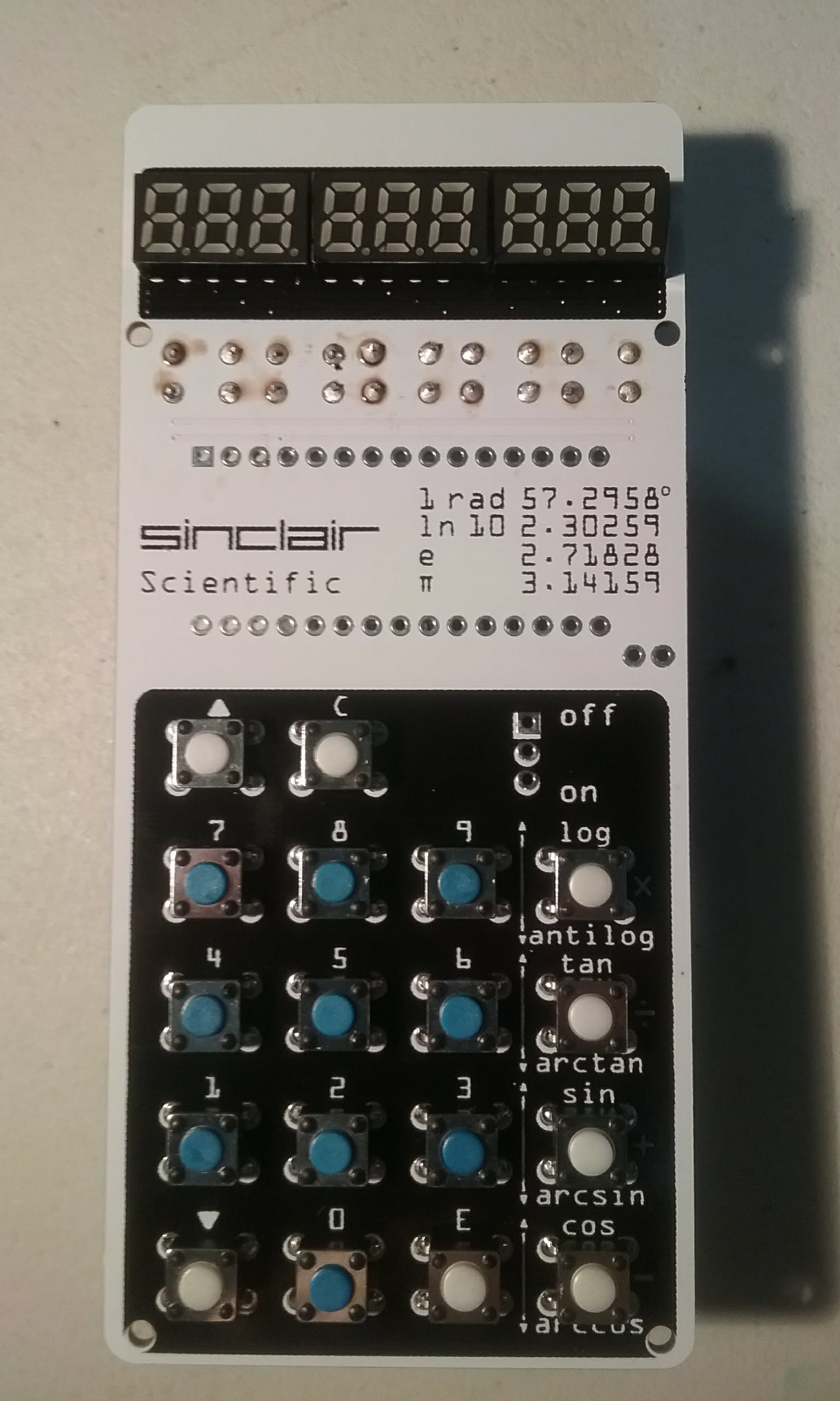
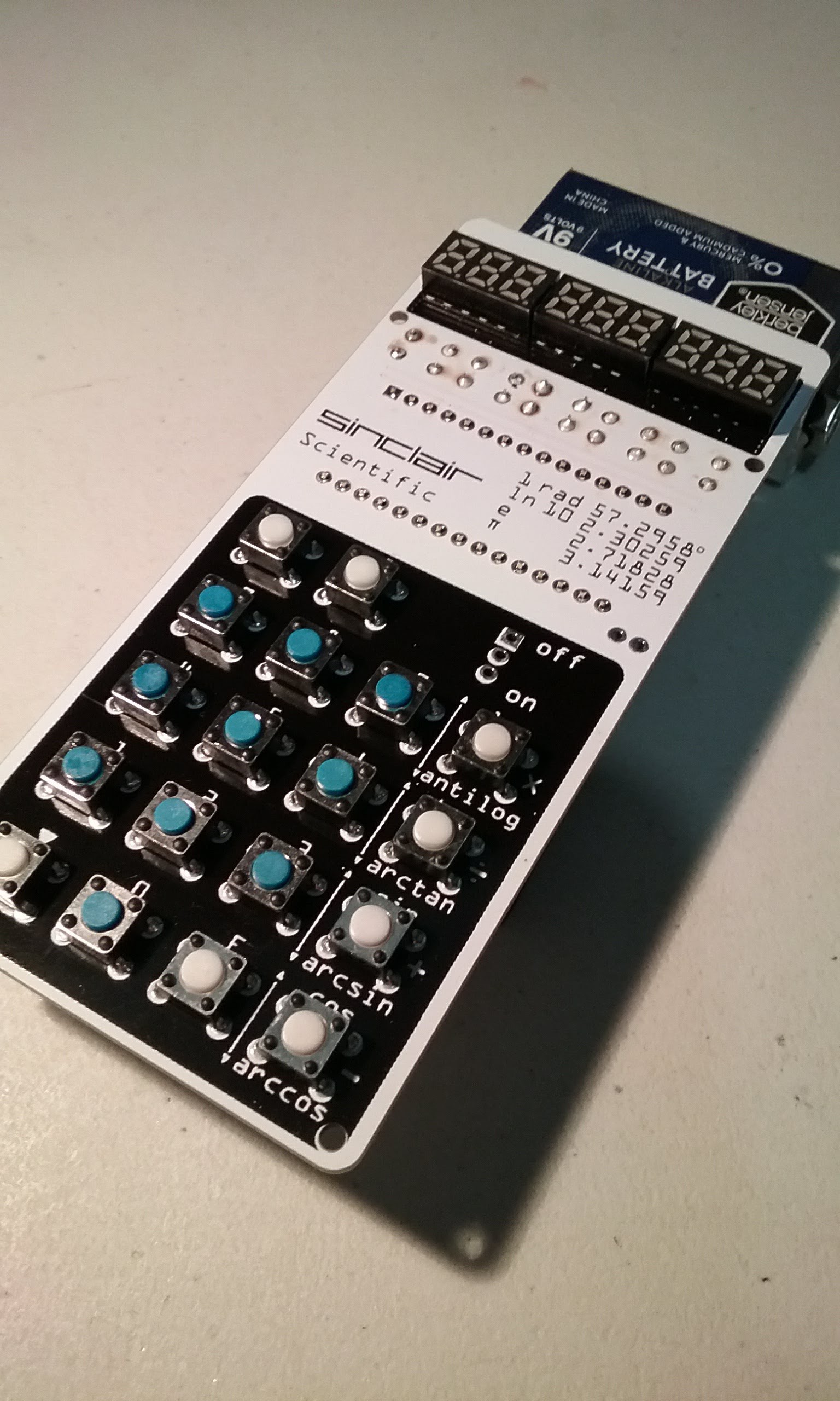
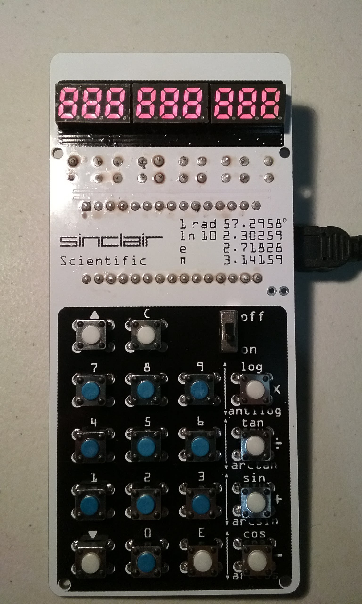
The blue buttons go in the number keys, the white ones go in the function keys. See WARNING above.
The buttons pins are wider apart on the horizontal dimension, so they only go in one way. Make sure no pins are bent on the way in.
The buttons act as jumpers to the bottom copper layer so all the legs must go in and be soldered. Normally, the top two pins are internally jumped, and the bottom two pins are also jumped. When the button is pressed, continuity is established between the top and bottom pins.
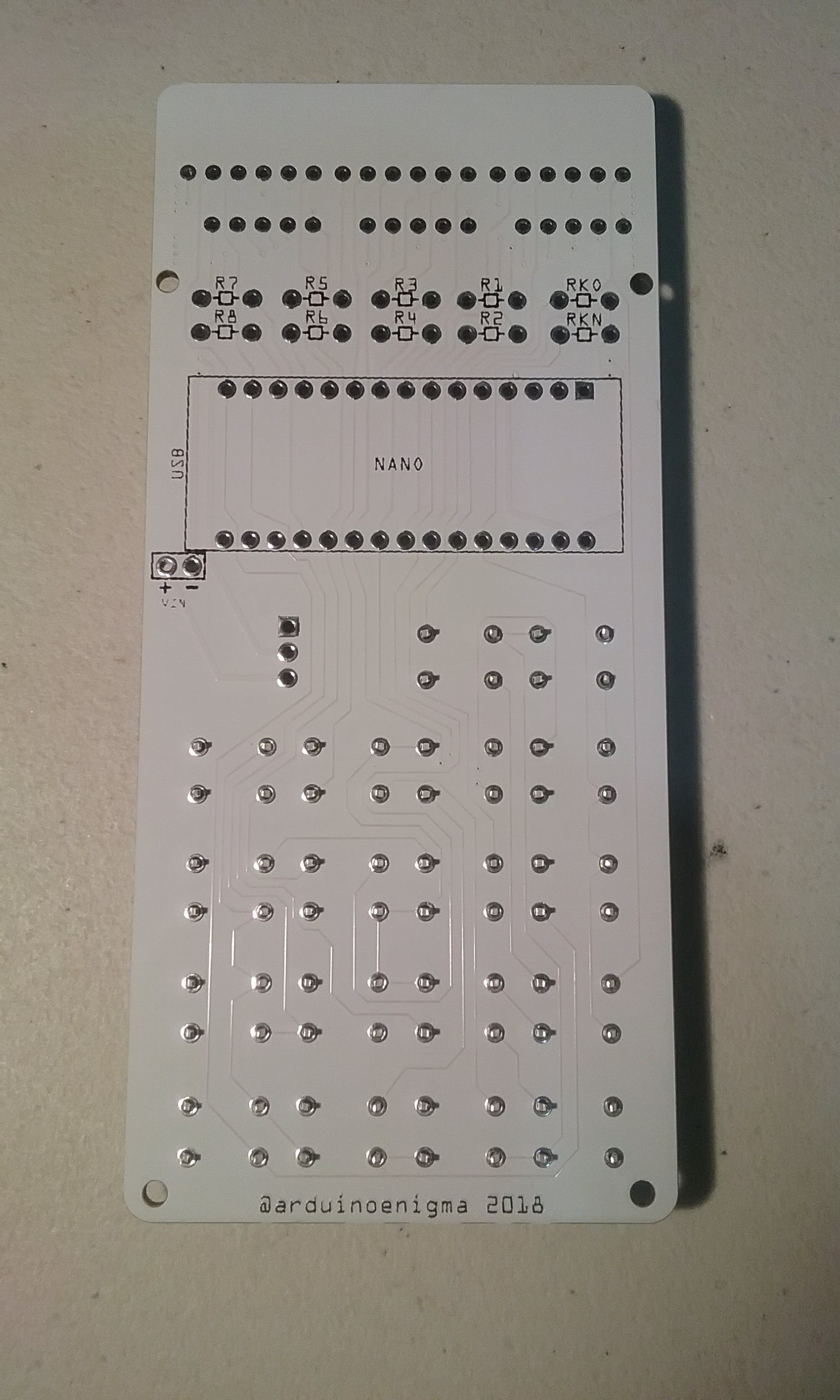
Flip the PCB over and make sure all the pins are in.
Flip the PCB again and make sure all the buttons are aligned. Once they are soldered they are kind of hard to straighten out. I check them often during soldering to make sure none has popped out..
Solder all the buttons. I like to go top to bottom starting on the far right column. Examine the solder joints and rework if necessary.
After the buttons are soldered, next is the current limiting resistors turn. These set the intensity of the LEDs. Smaller values will make the LEDs brighter, but shorten the battery life.
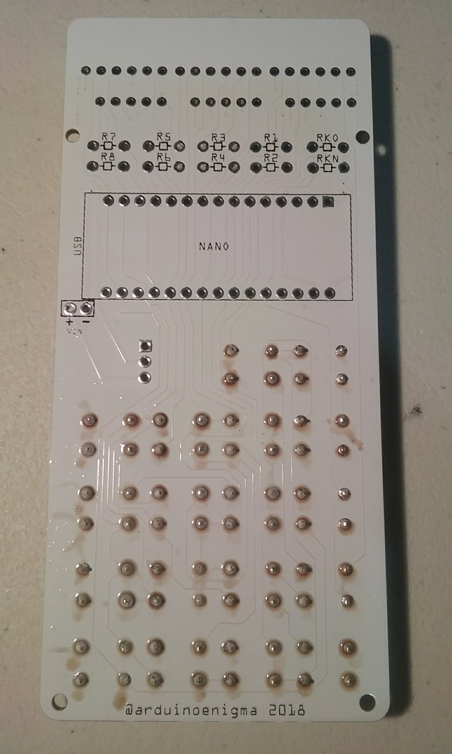
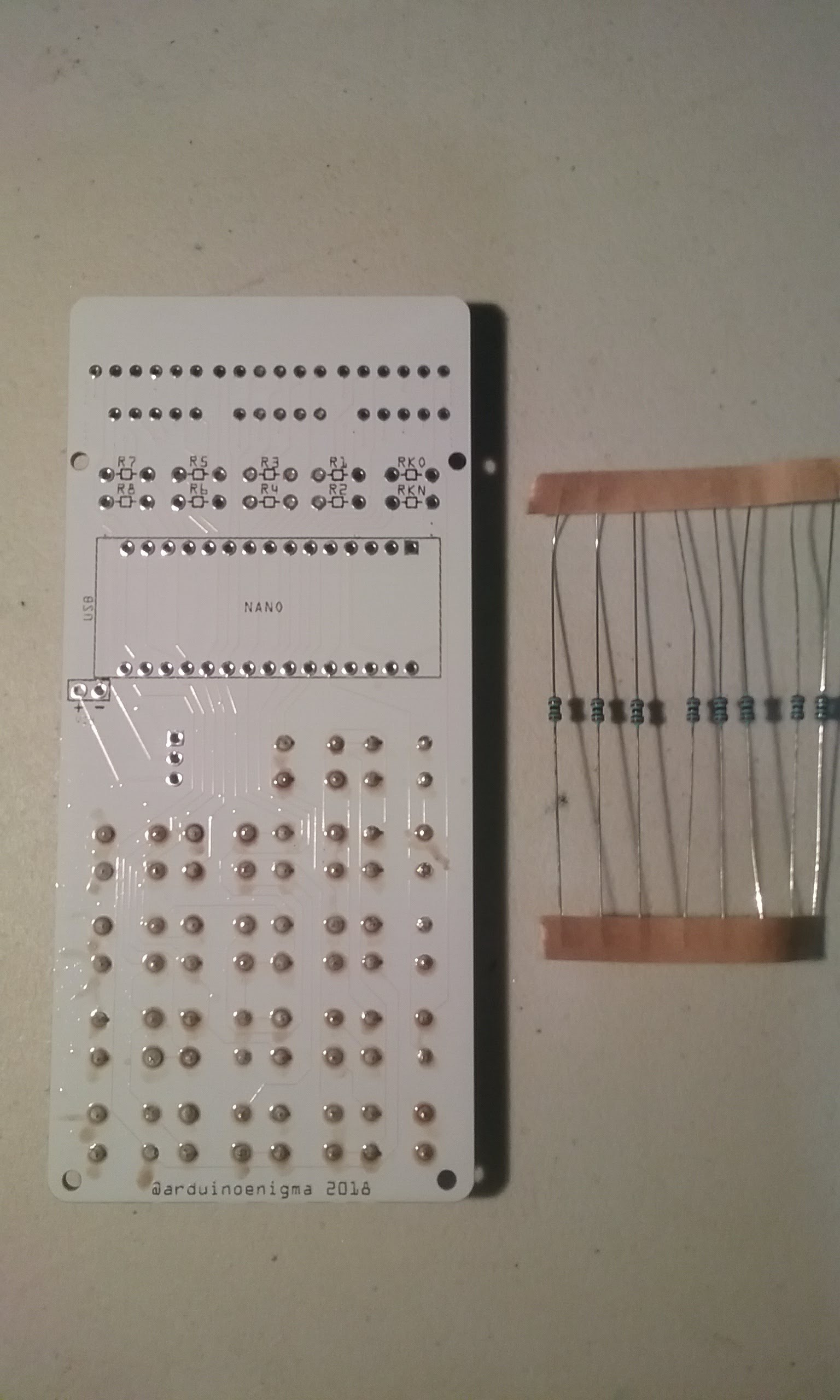
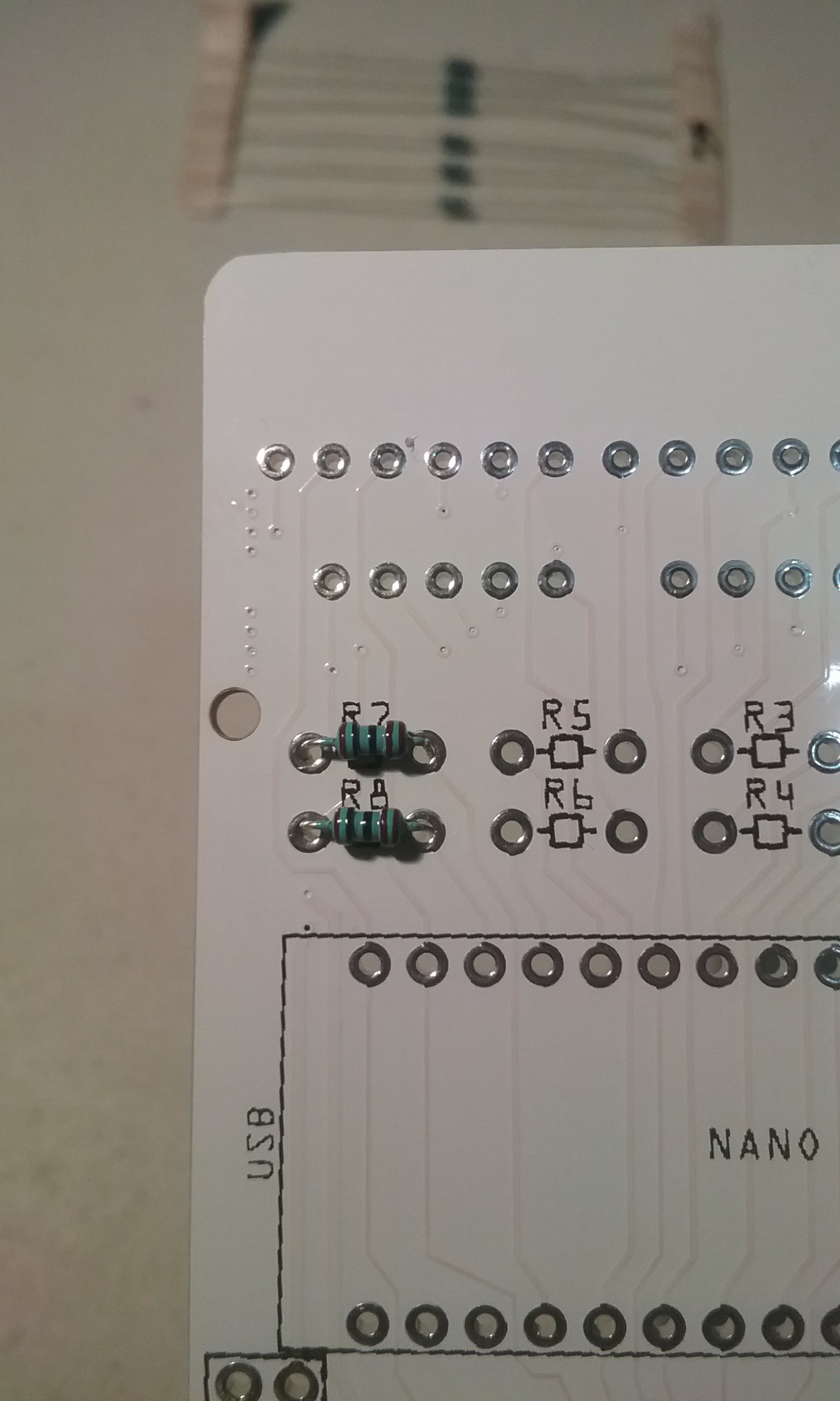
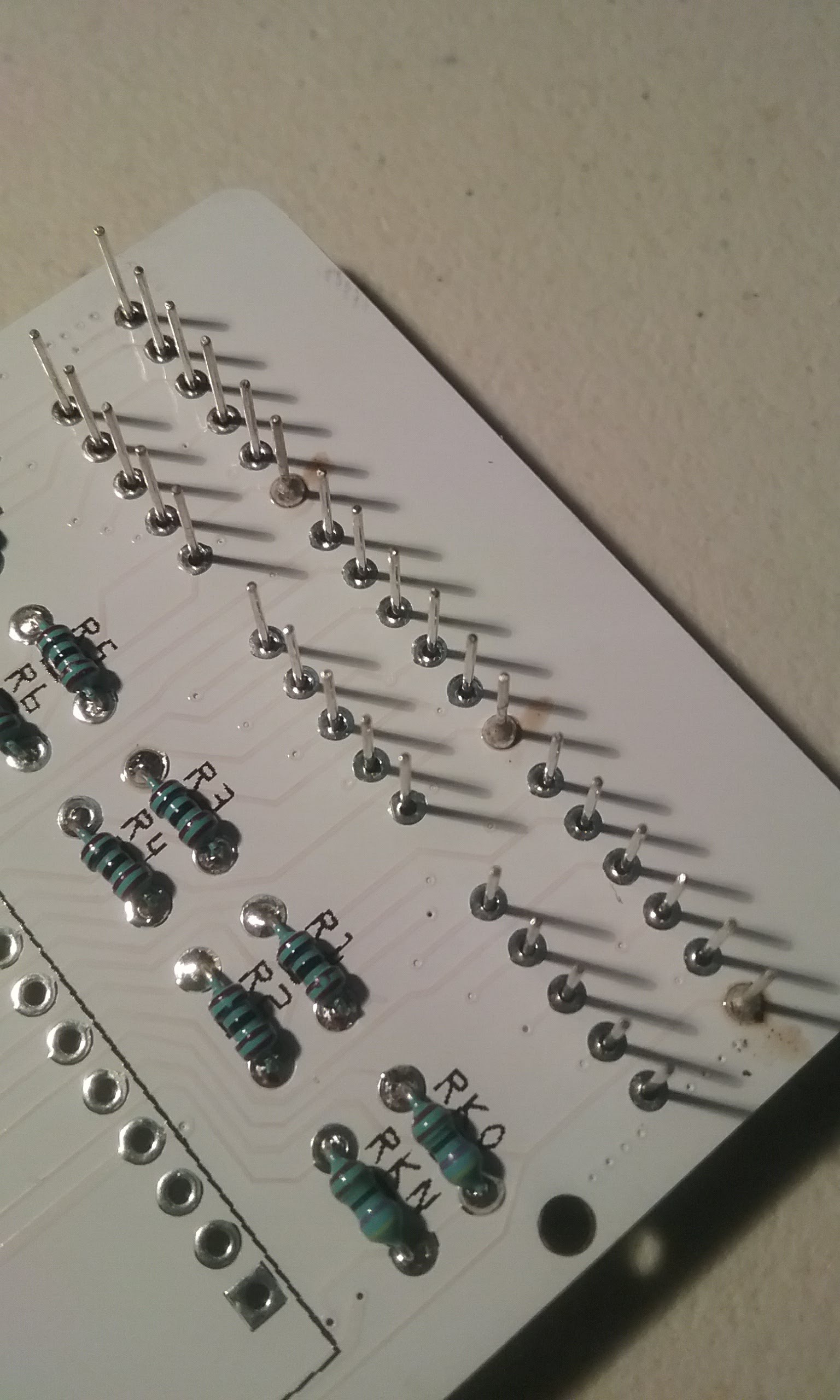
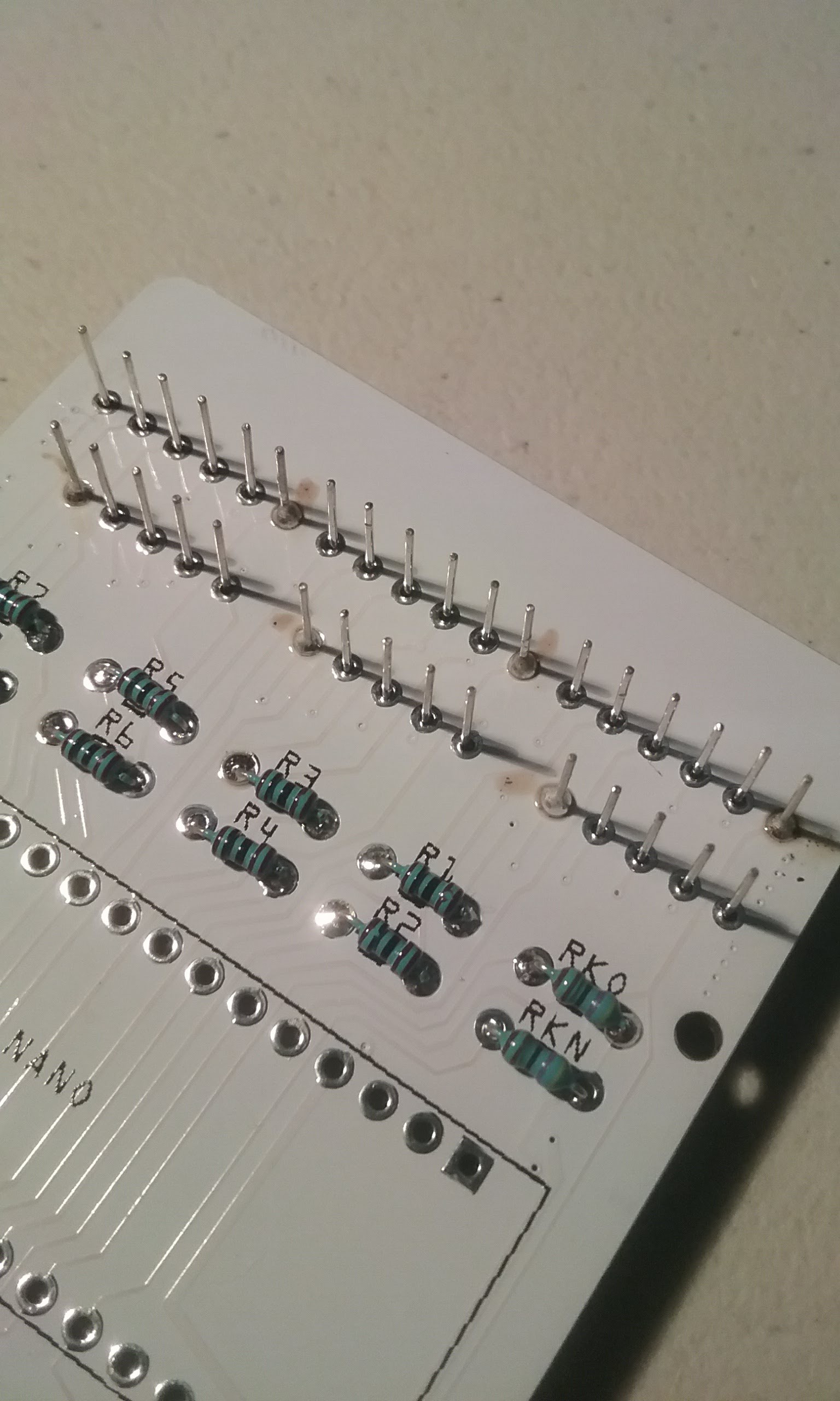
Find the strip with 8x 1K resistors. Those will go on R1 through R8. Do not populate RKO and RKN at this time. Do not confuse the resistors or the brightness of individual segments will be different.
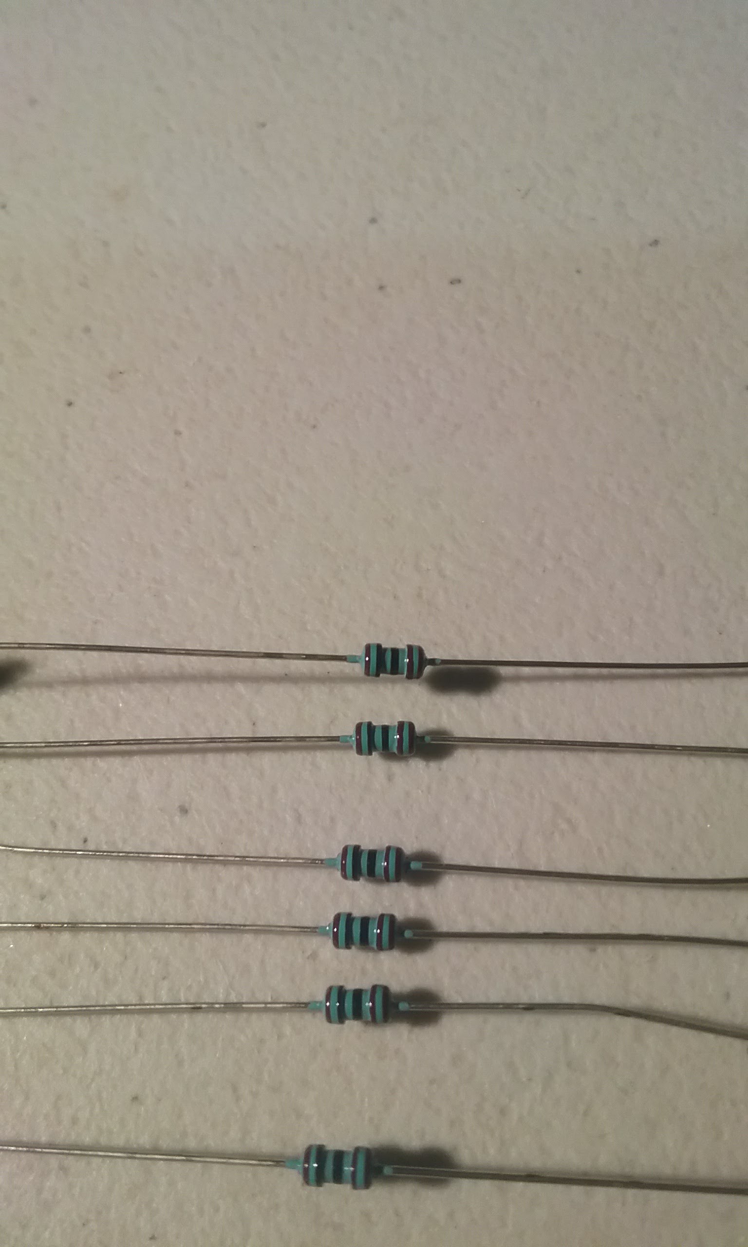
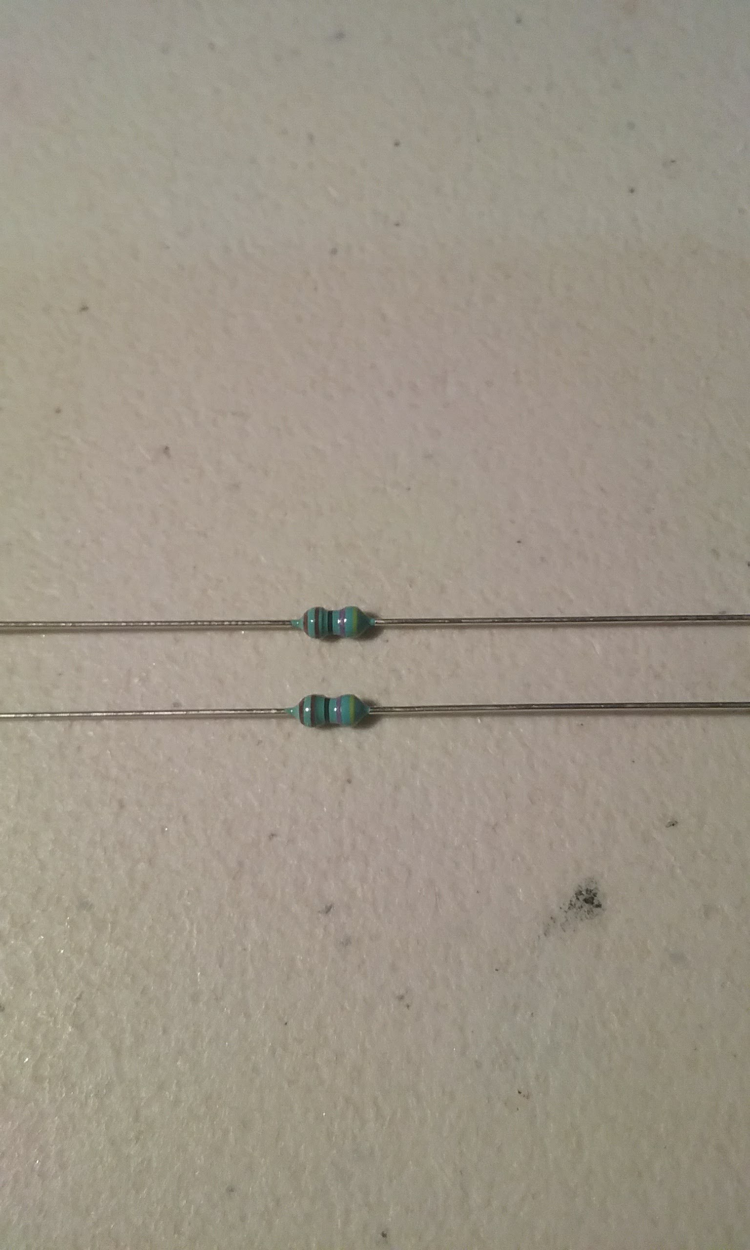
A close up of what a 1K is supposed to look like, brown and black lines. The 4.7K have a yellow band on one end.
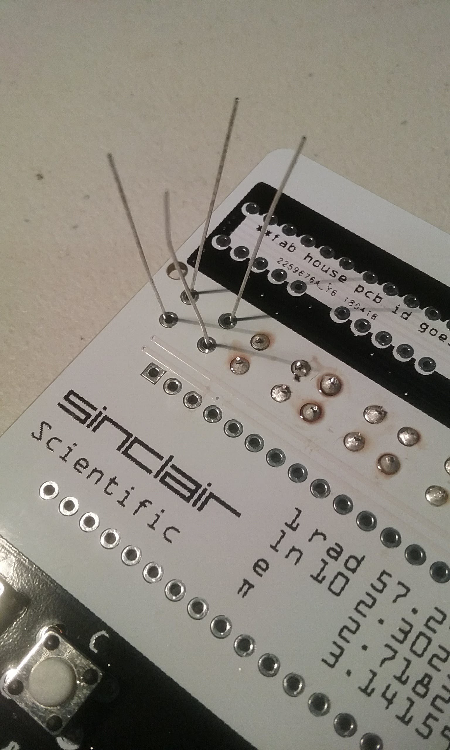
Bend the legs close to the body and insert from the bottom of the board.
Flip the board and while pushing down, solder the legs.
Once soldered, trim the legs.
Continue doing two at a time until R1 through R8 are populated.
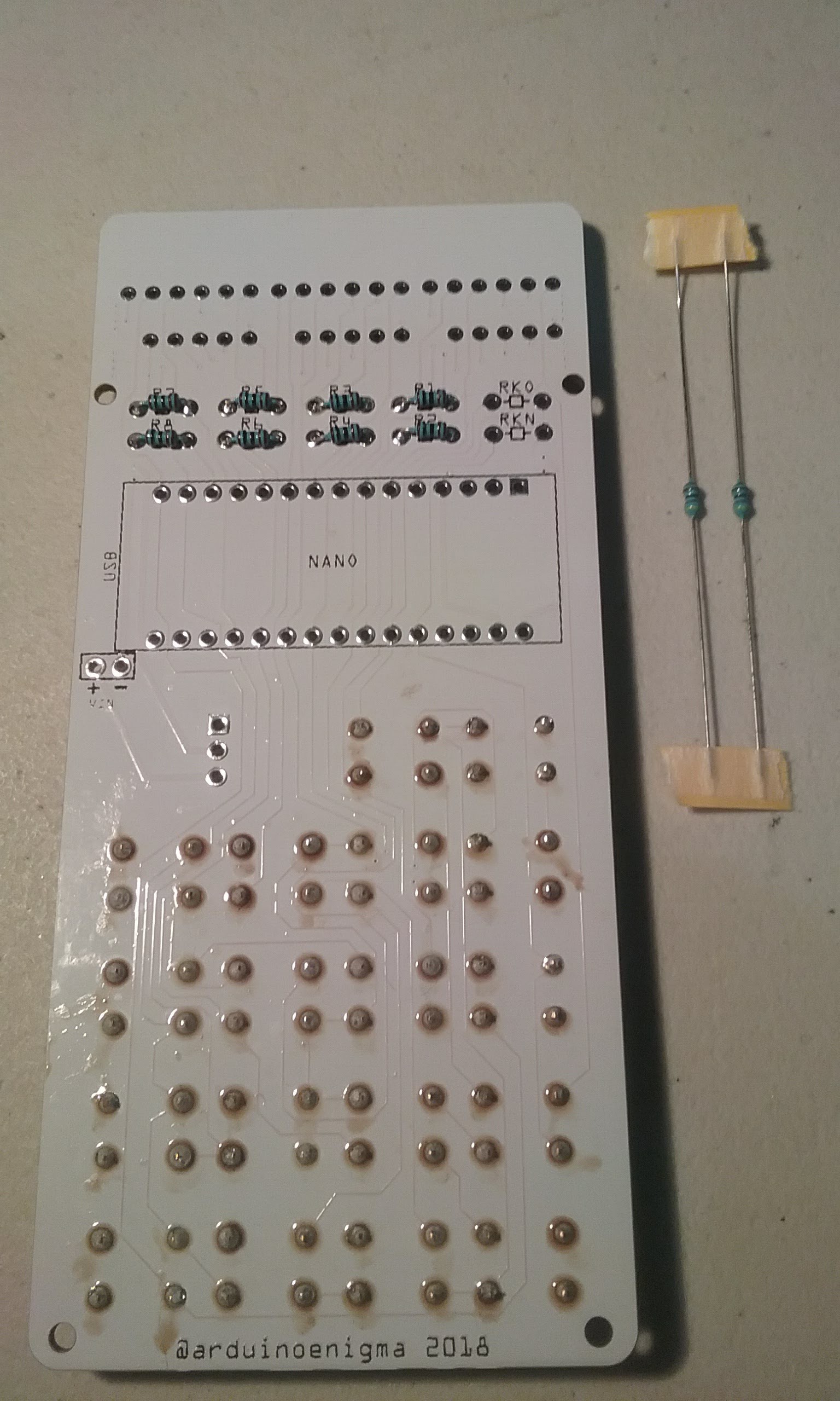
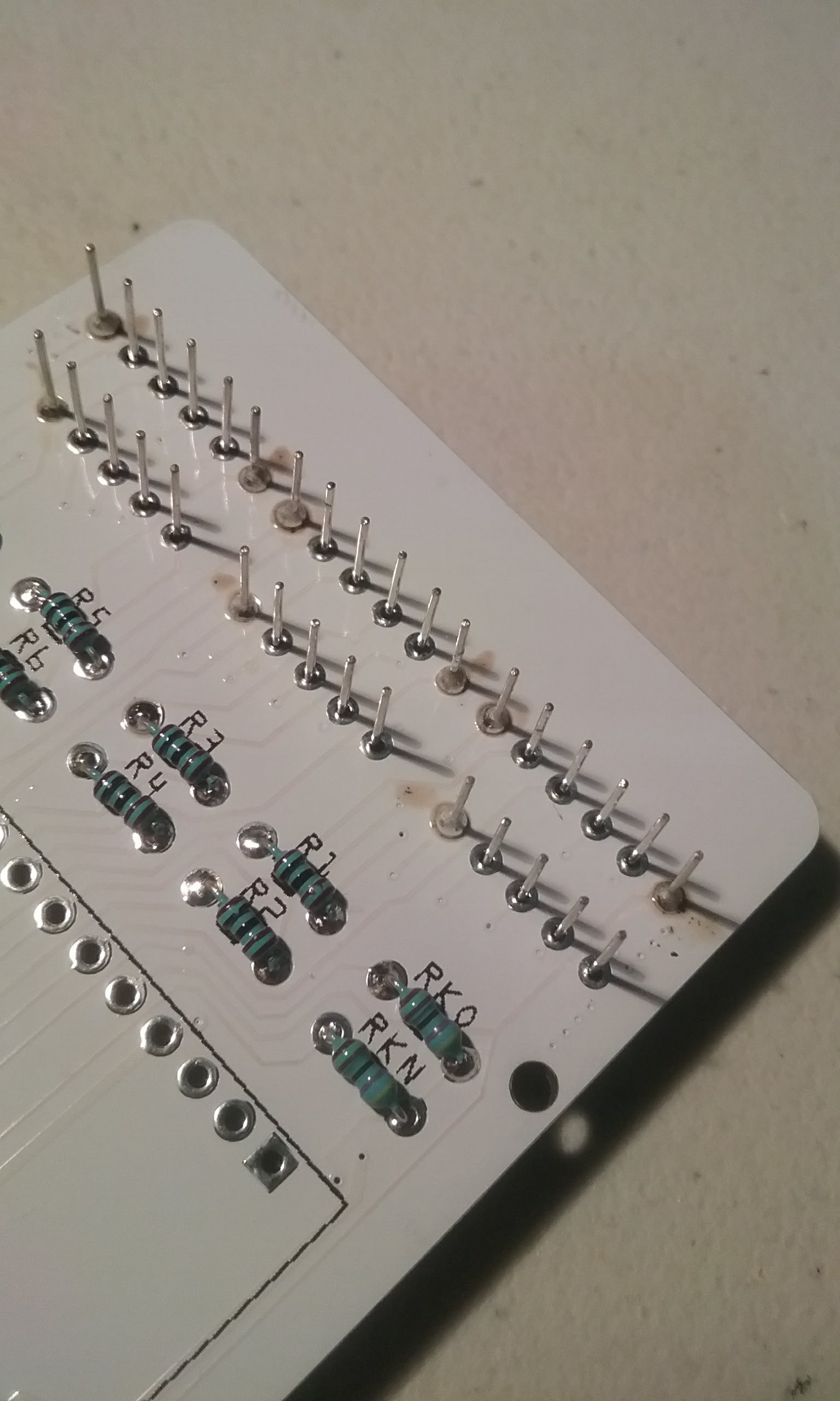
This is how the board is supposed to look like at this point.
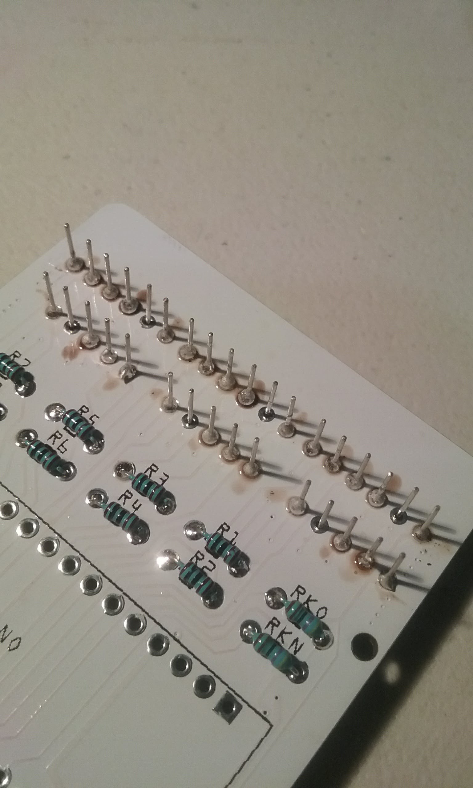
Next, lets put the 4.7K resistors on RKO and RKN. These are weak pull down resistors and could be substituted with another high value resistor.
The 4.7K resistors have a yellow line on one end.
Bend the legs and insert them through the bottom of the PCB.
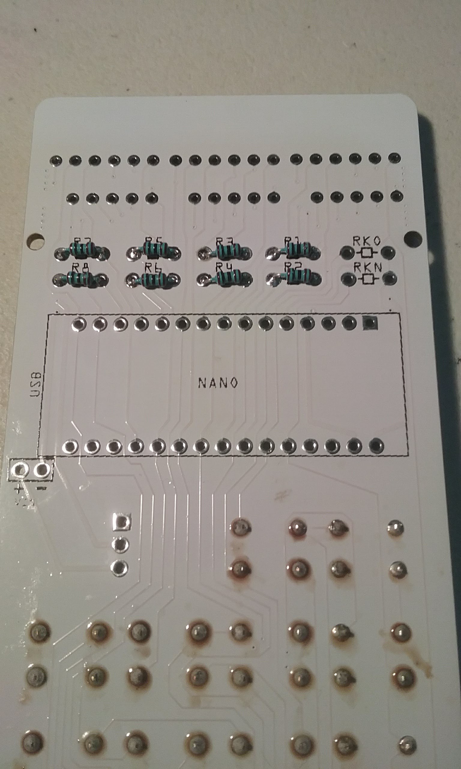
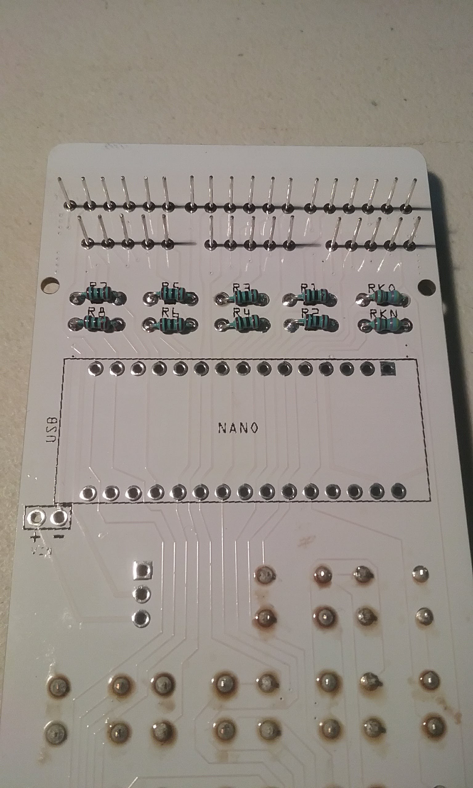
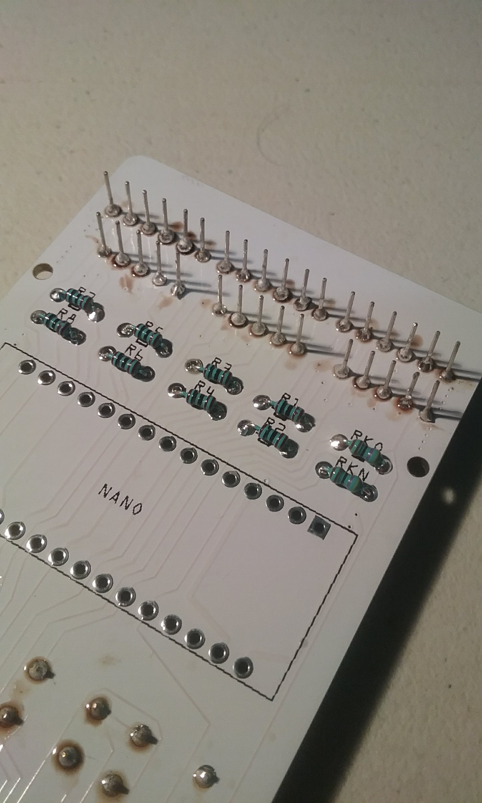
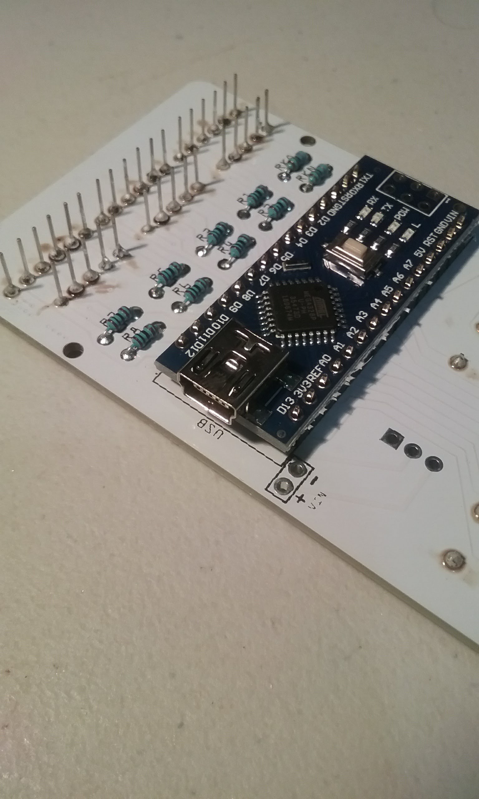
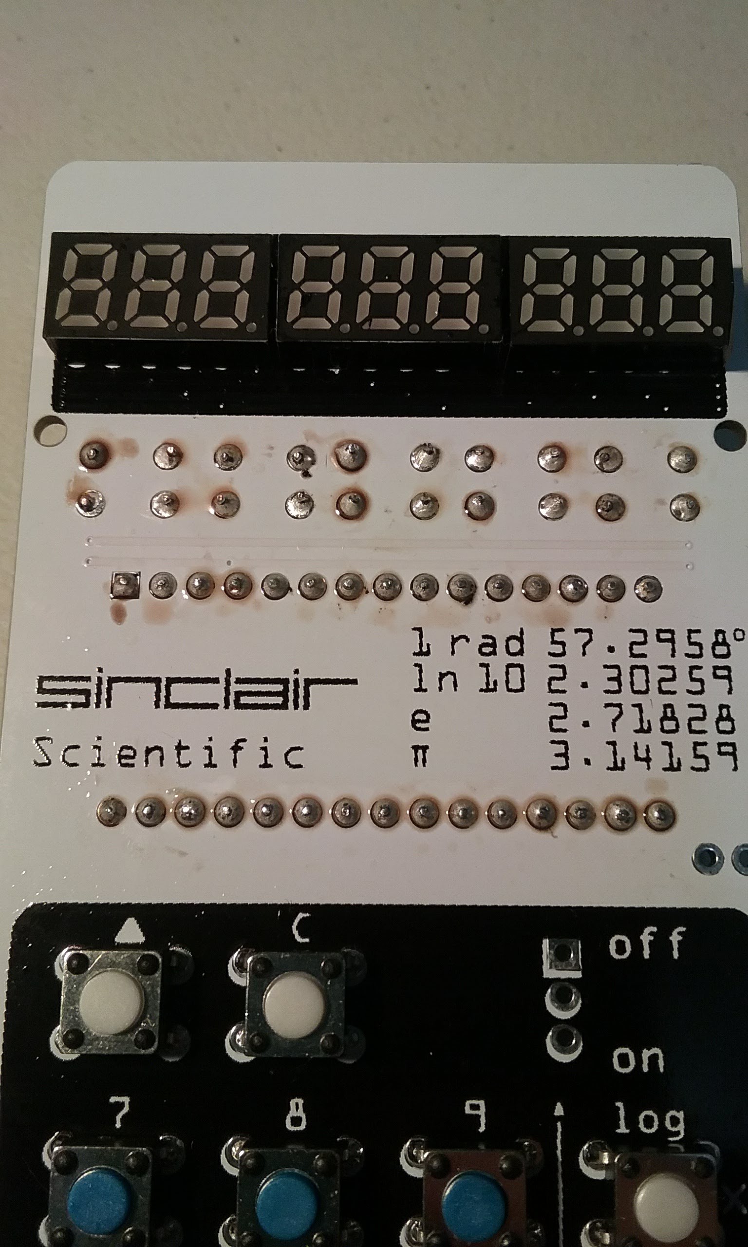
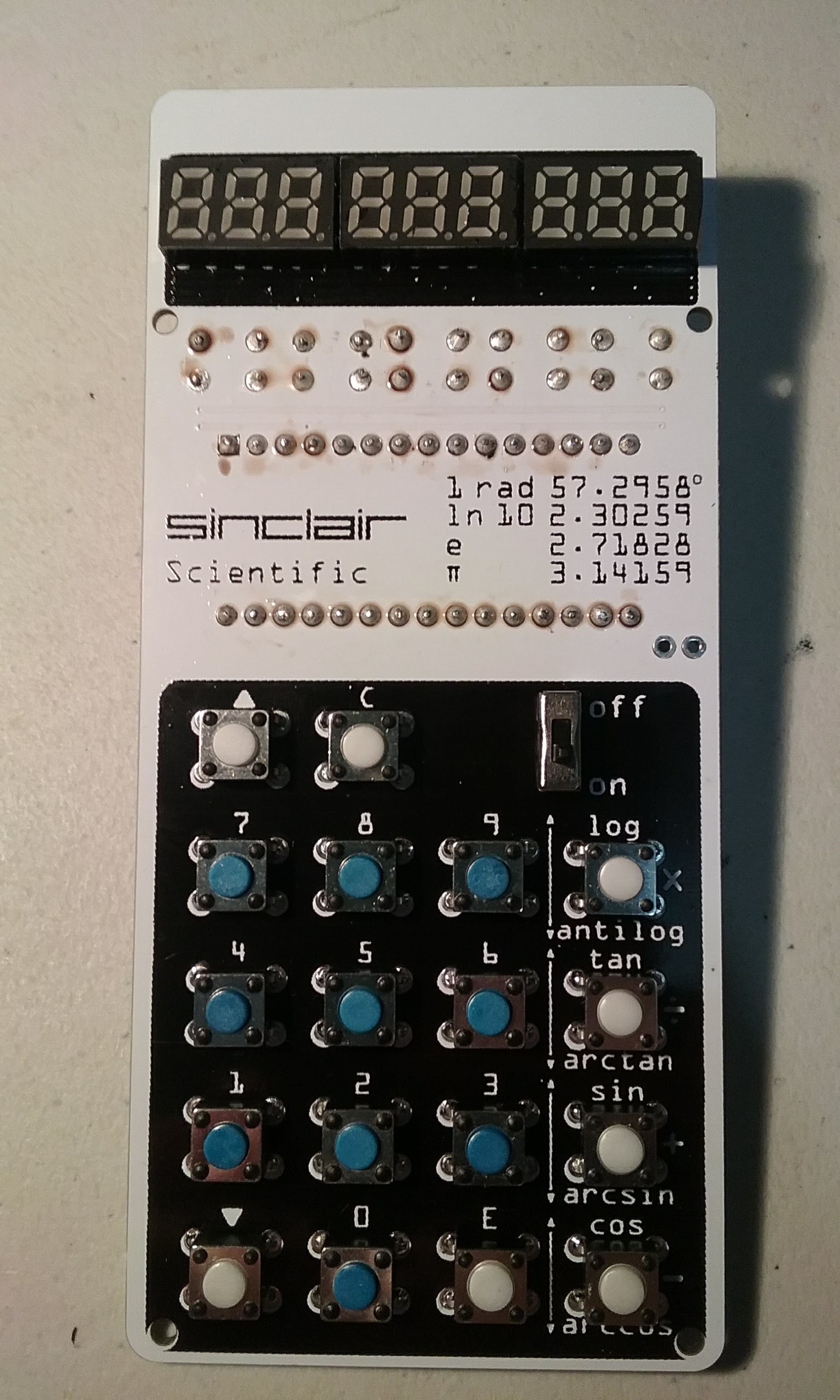
Solder and trim. By now all the keys and all the current limiting resistors should be soldered. The top of the board should look like this:
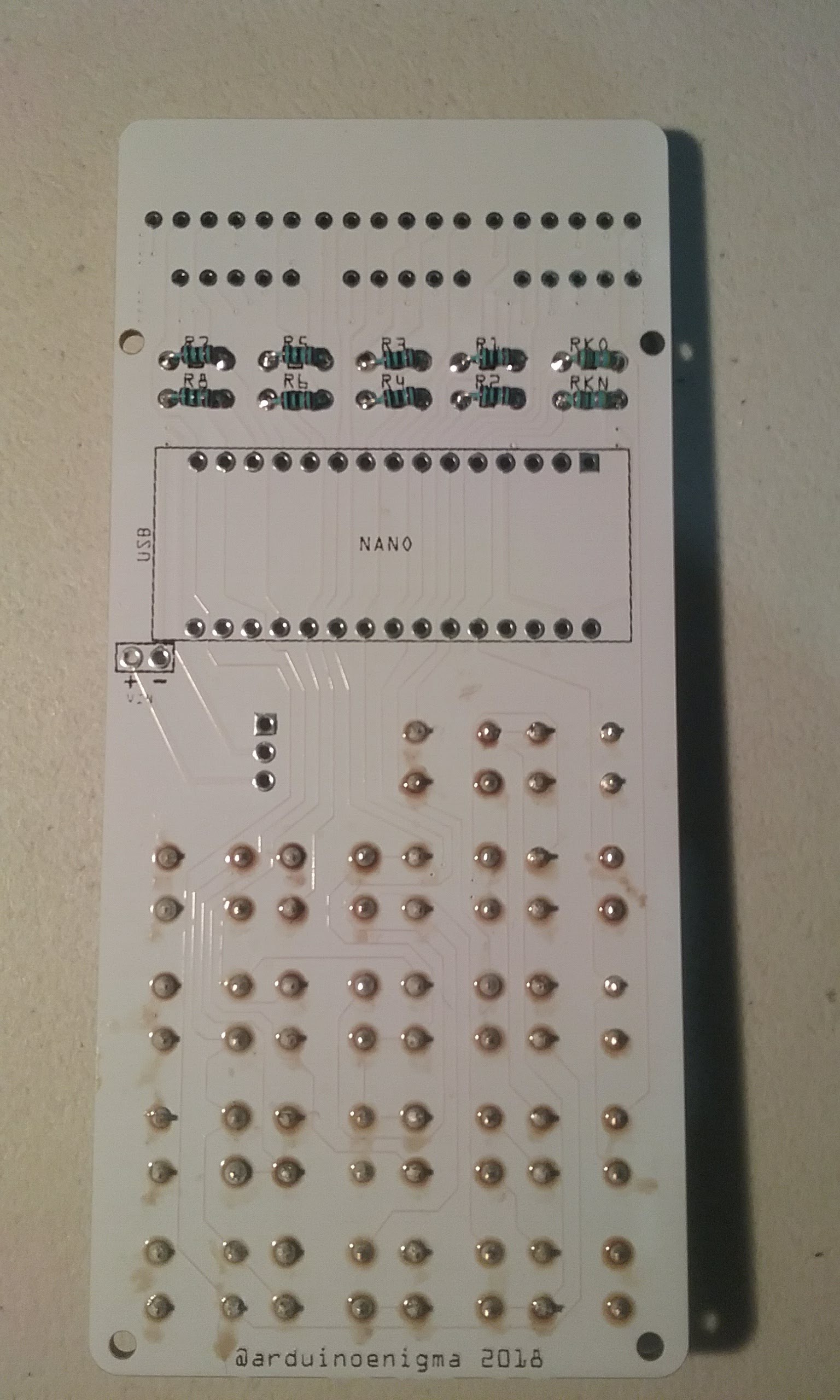
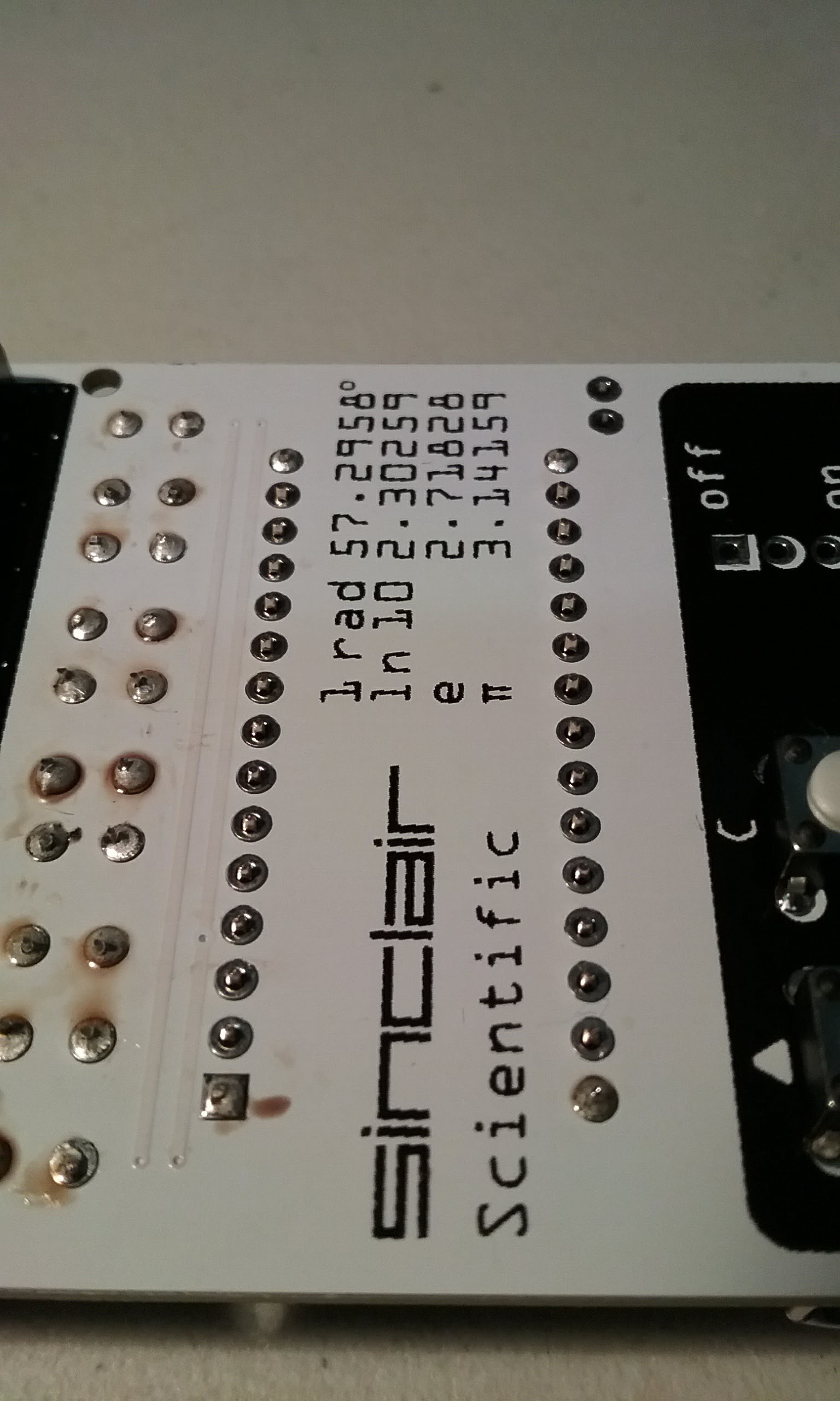
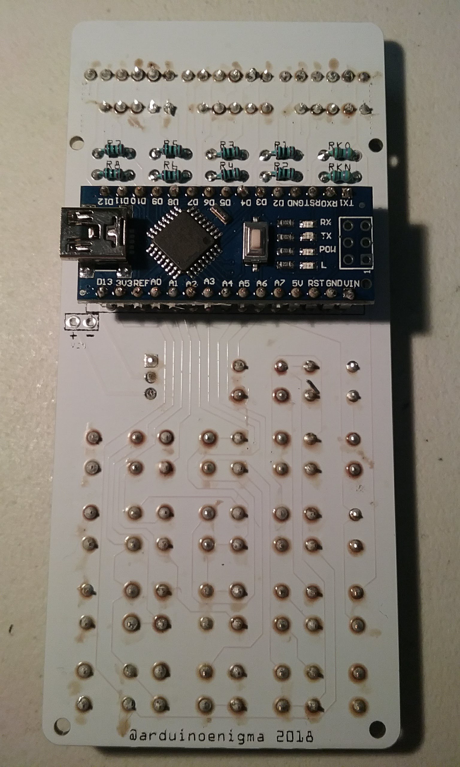
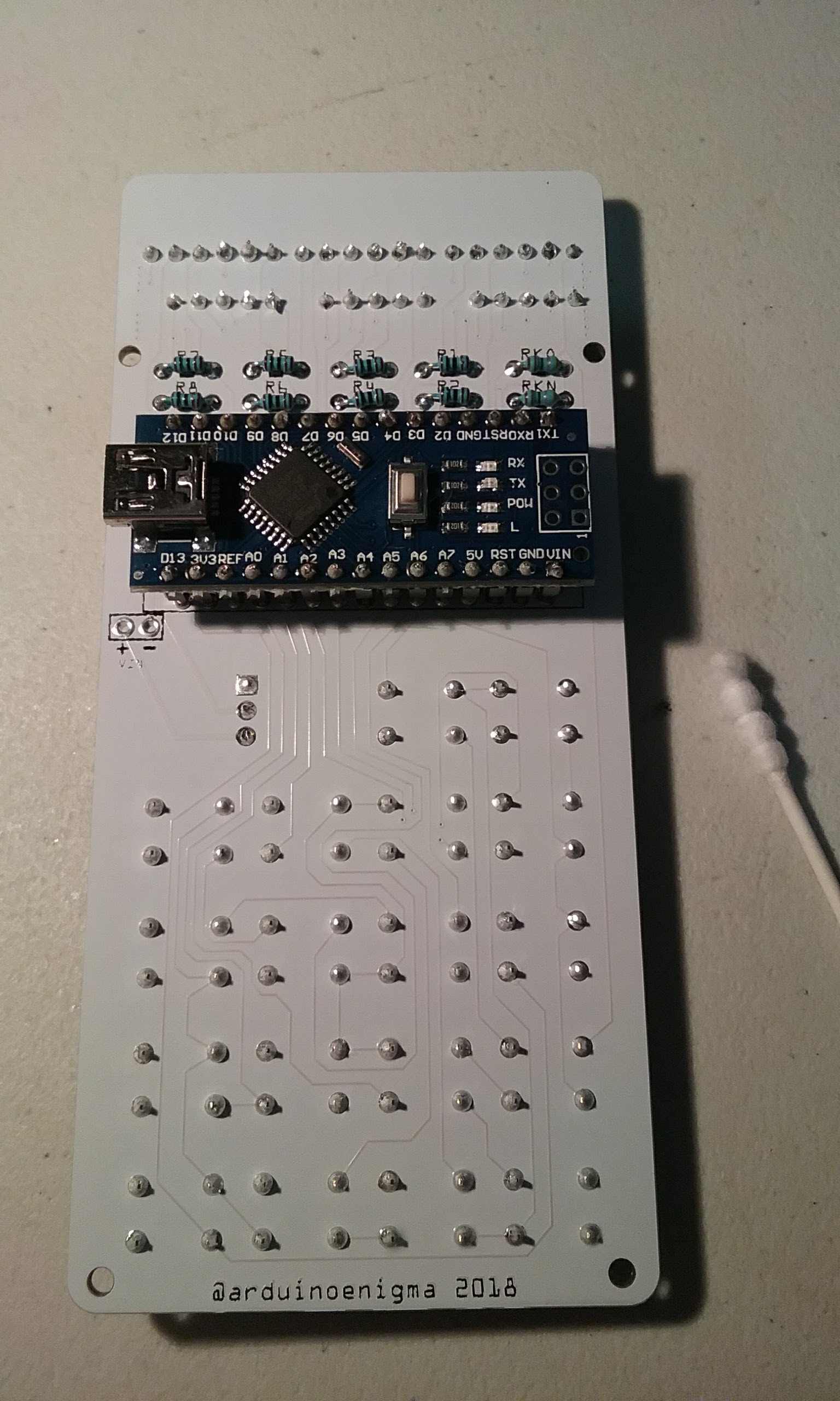
And here is the bottom of the board at this stage:
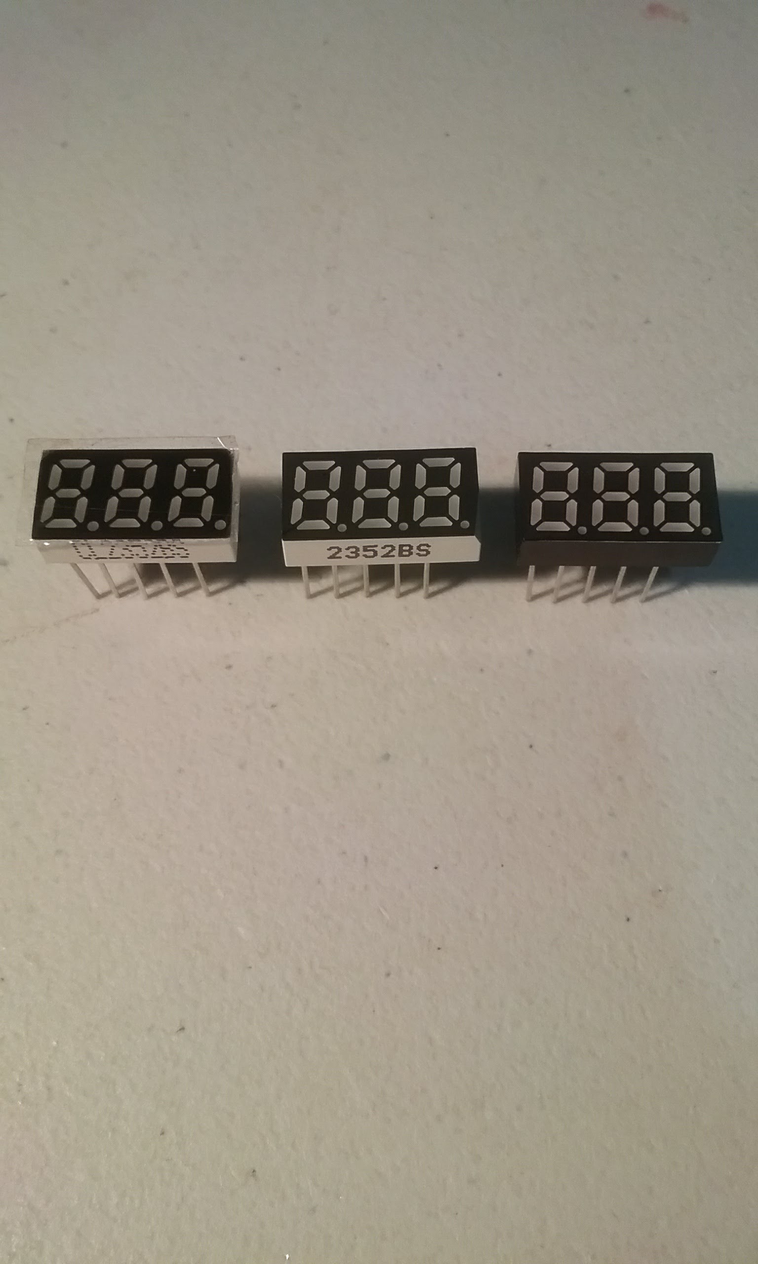
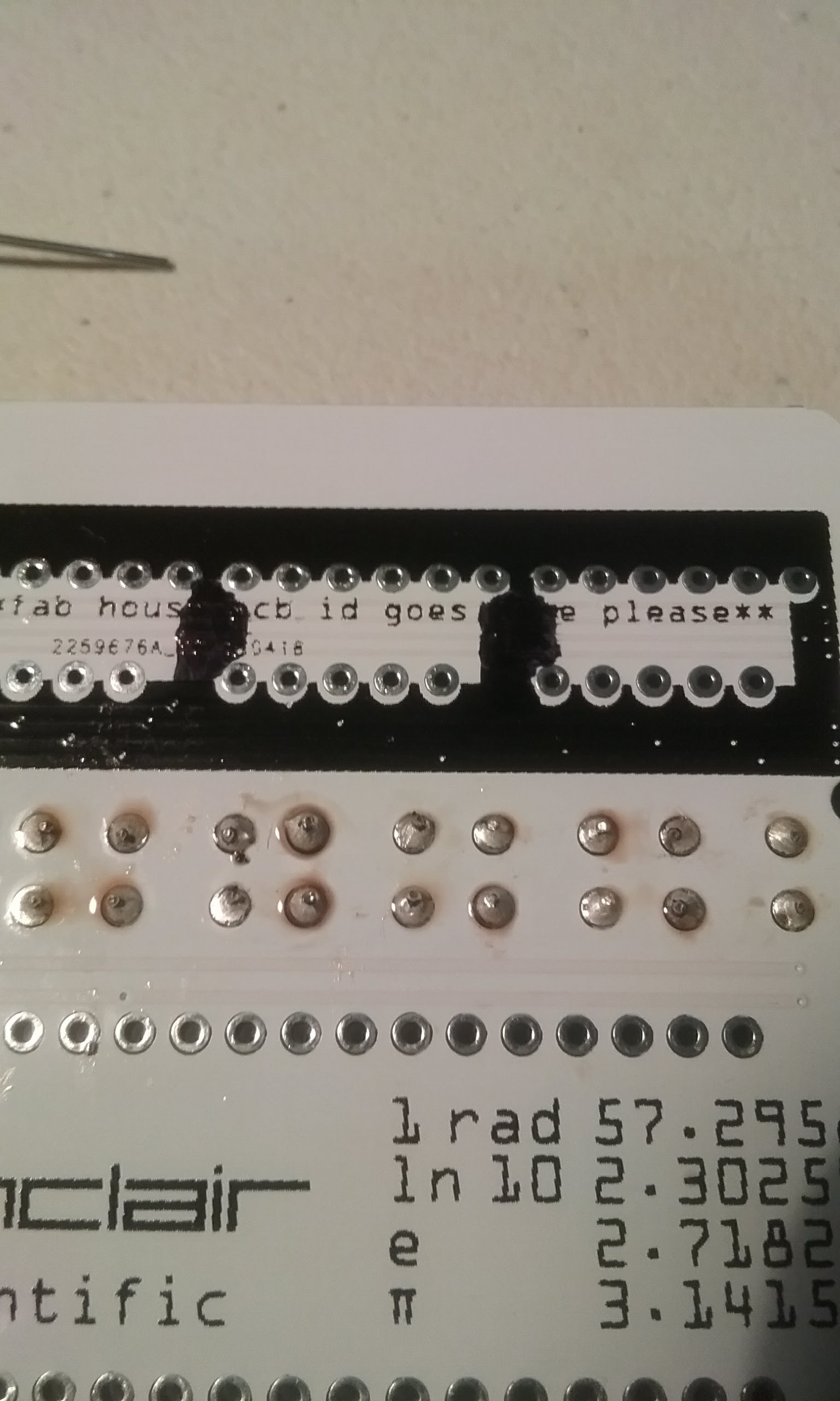
Next we will prepare the displays. They come with a plastic film over the top. It can be pulled, as it is bigger than the display. Next, using a Permanent Marker, make the sides of the display black.
Using the Permanent Marker, color the following space in the PCB. This will prevent the white soldermask to show in between the displays.
Next, insert the displays on the PCB. They are keyed and only go in one way.
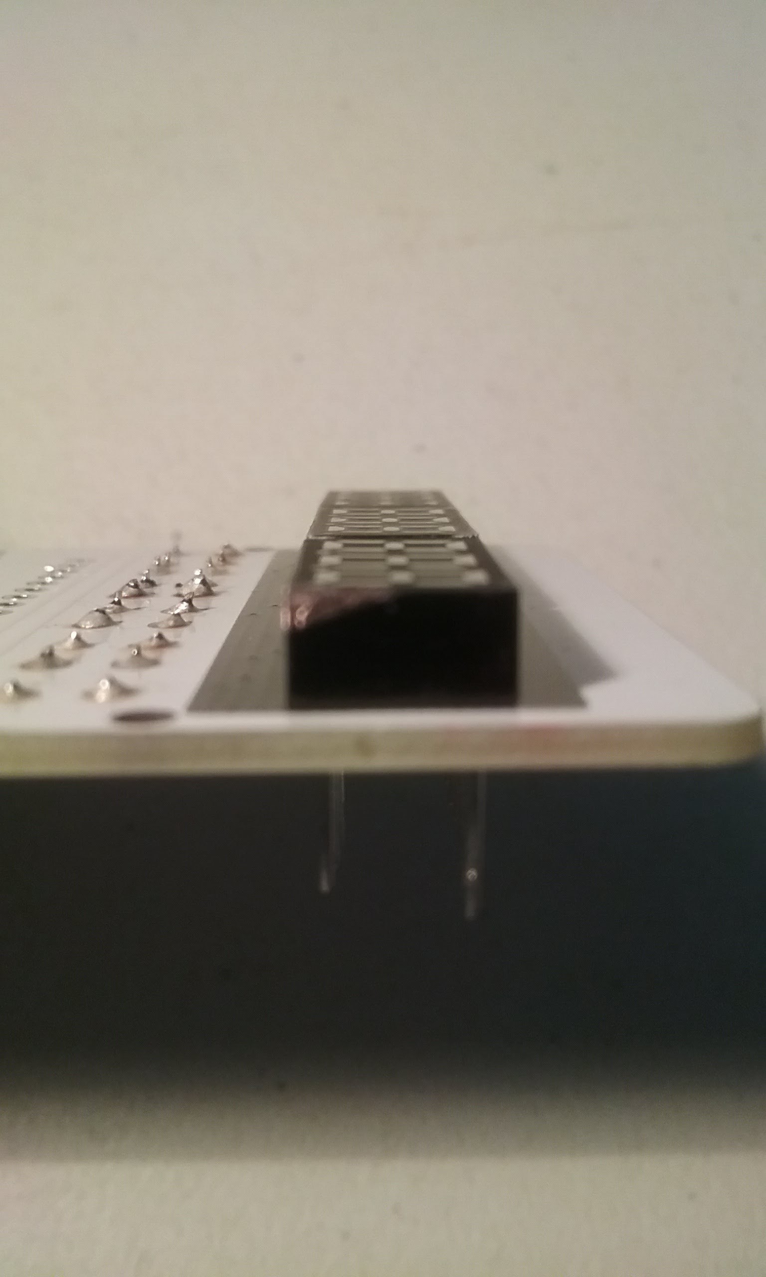
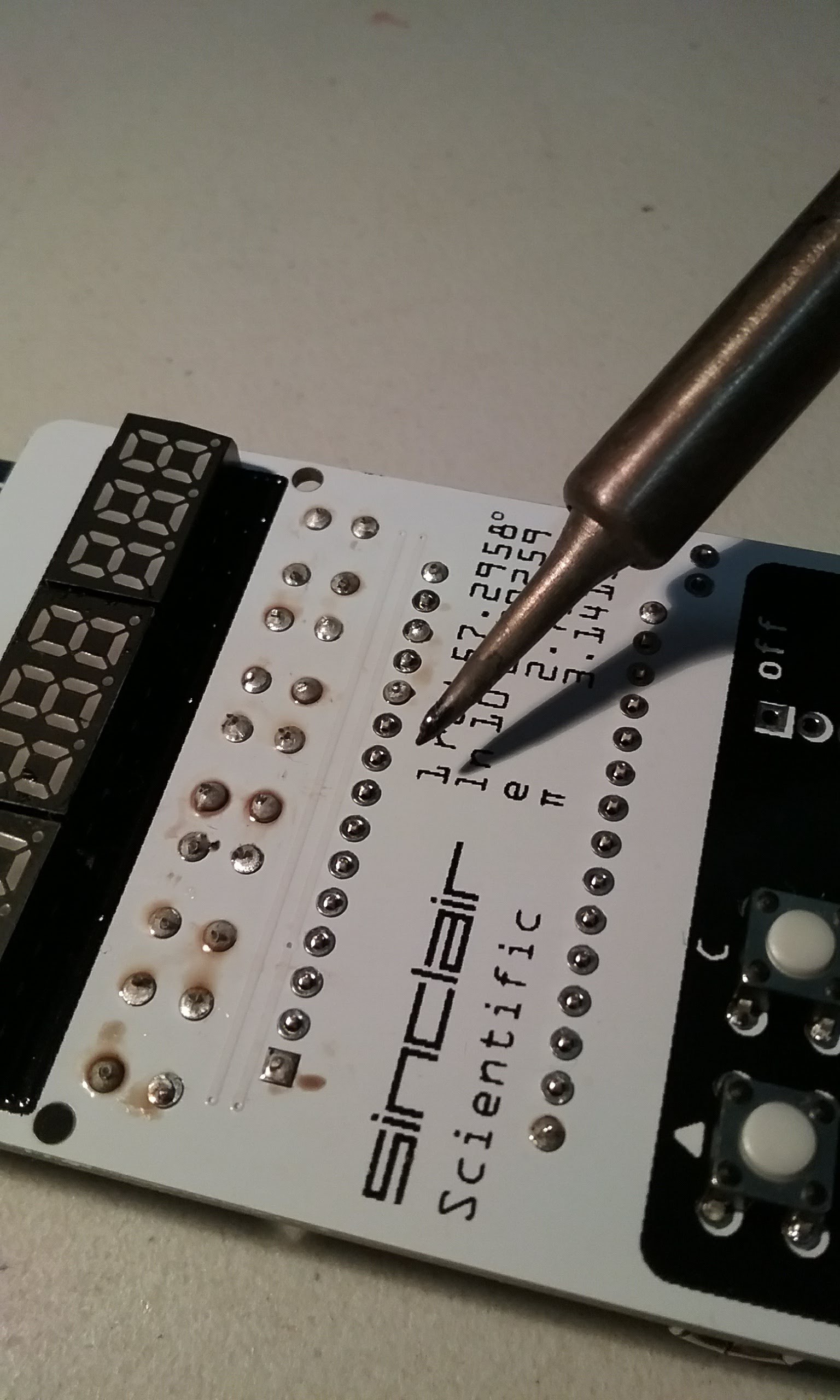
This is how it how the bottom of the board should look like at this point.
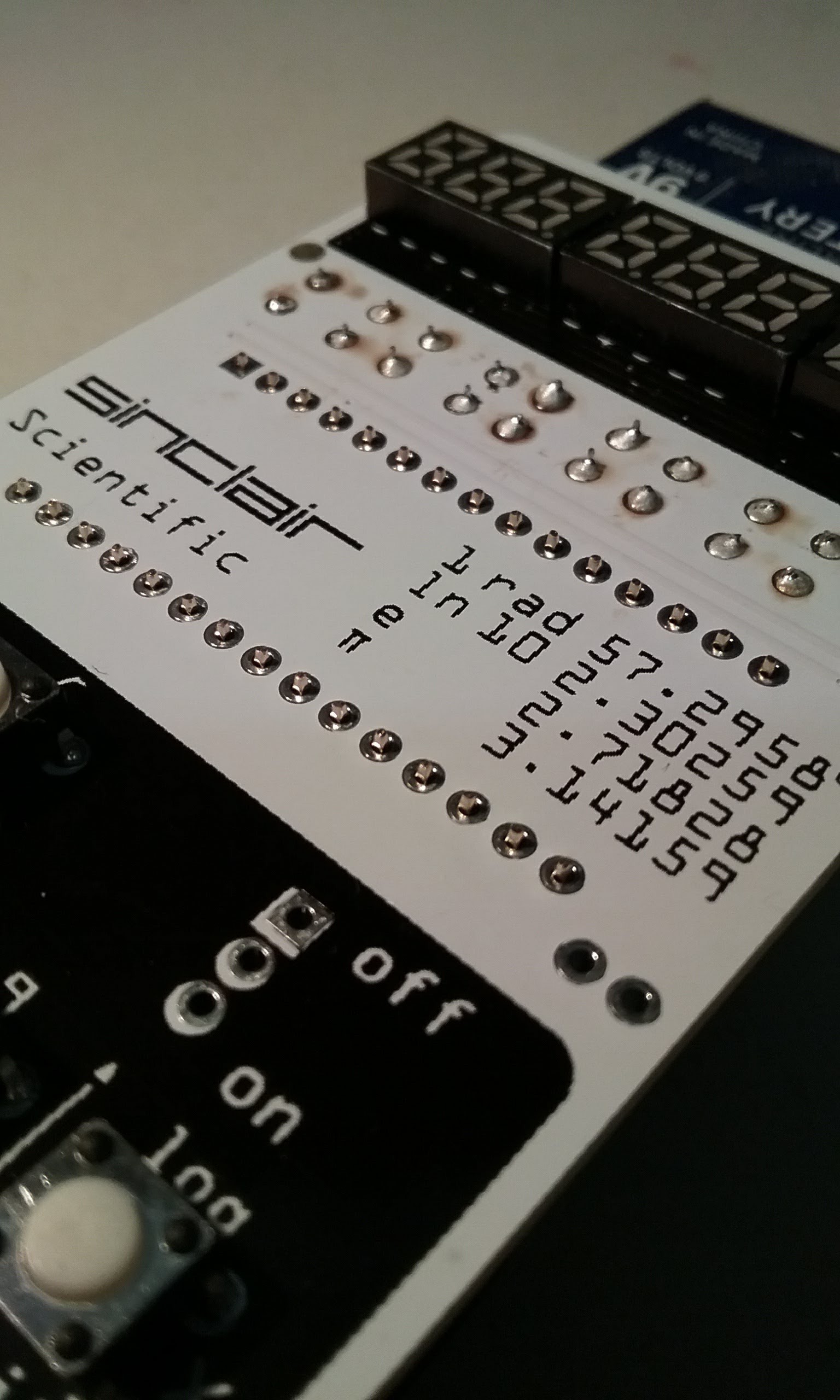
While pushing down on the board and the displays to insure they are fully seated, solder one pin on each display.
Flip the board over and ensure the displays are aligned, top, bottom and face.
Flip the board over and solder one more pin on each display. I like alternating the row and working from the outside in to avoid heating the displays.
Solder more pins, keep alternating rows.
Last one on each row.
And they are fully soldered, do not trim the legs for now. Lets solder the Arduino first and make sure everything is working.
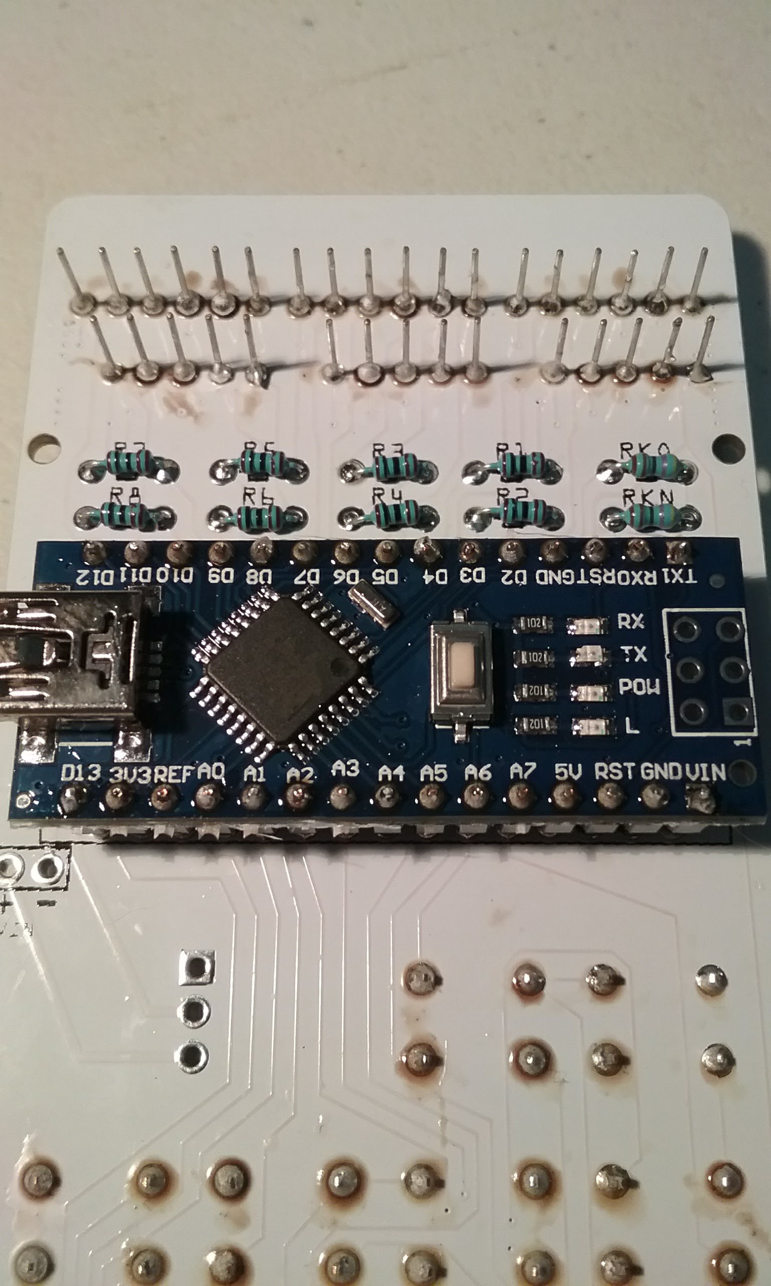
Next is the Arduino. This particular model ships with unsoldered headers. Observe static electricity precautions.
Flip the PCB to the back and place the headers with the short side facing the Arduino. Ensure the Arduino is inserted in the correct orientation: USB connector visible and pointing to the side of the PCB marked USB.
Solder one pin on each corner of the Arduino.
Flip the PCB over and push the pins down until they barely protrude. The goal here is to have the pins concealed inside the solder ball and not have to do any trimming. Ensure all pins protrude equally.
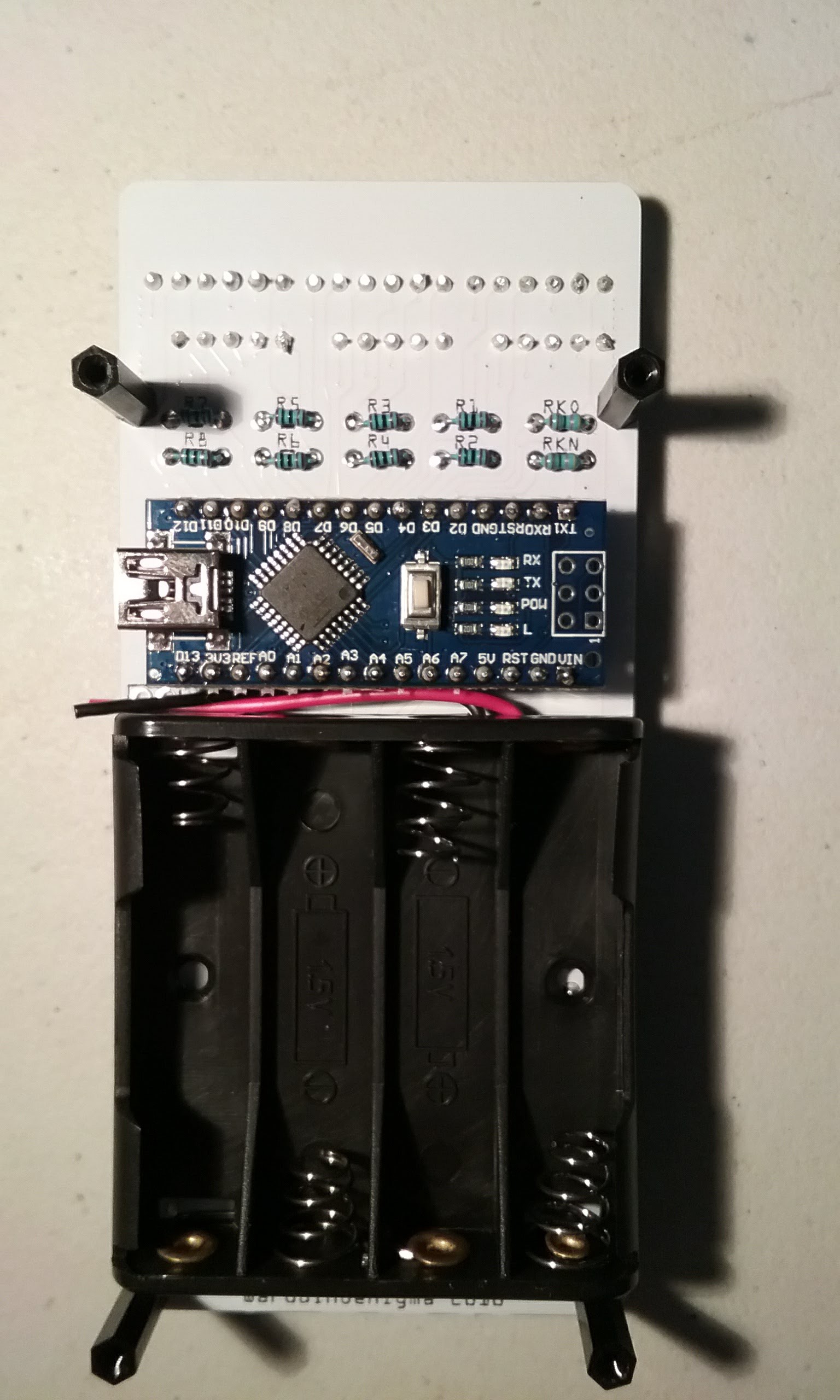
Lift the PCB off the bottom so you are not pushing down on the Arduino. Here I am using a couple of 9V batteries. The standoffs could be installed at this point.
Solder each corner of the chip.
If satisfied, continue soldering. Mind the orientation of the soldering iron. It is easy to lose positional awareness and touch either the displays or the buttons with the hot iron.
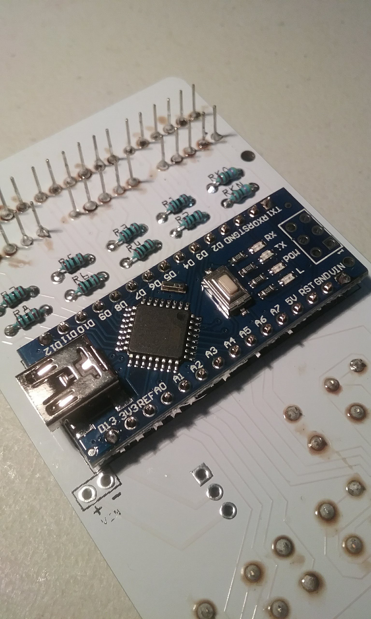
Finish soldering all the pins in the front.
Flip the board over and solder all the pins in the Arduino.
Almost done with the soldering. Flip the board over and place the power switch. The orientation is not important.
Flip the board and solder one leg of the power switch.
Check the alignment of the power switch and finish soldering its legs. Only the center and bottom pins are important, the square pad is not connected to anything. We will solder it anyways for mechanical stability.
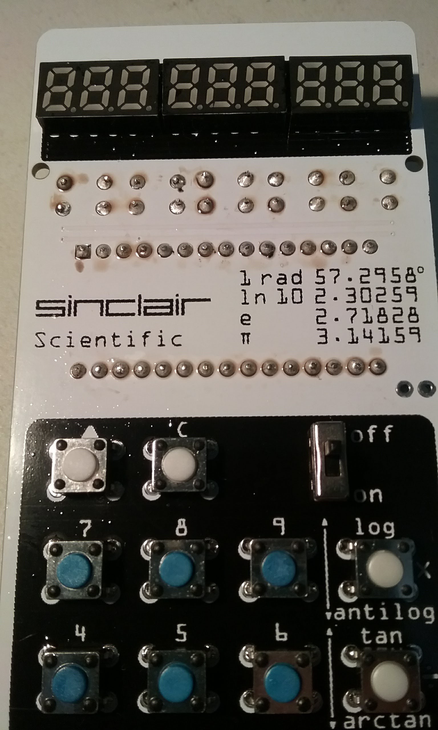
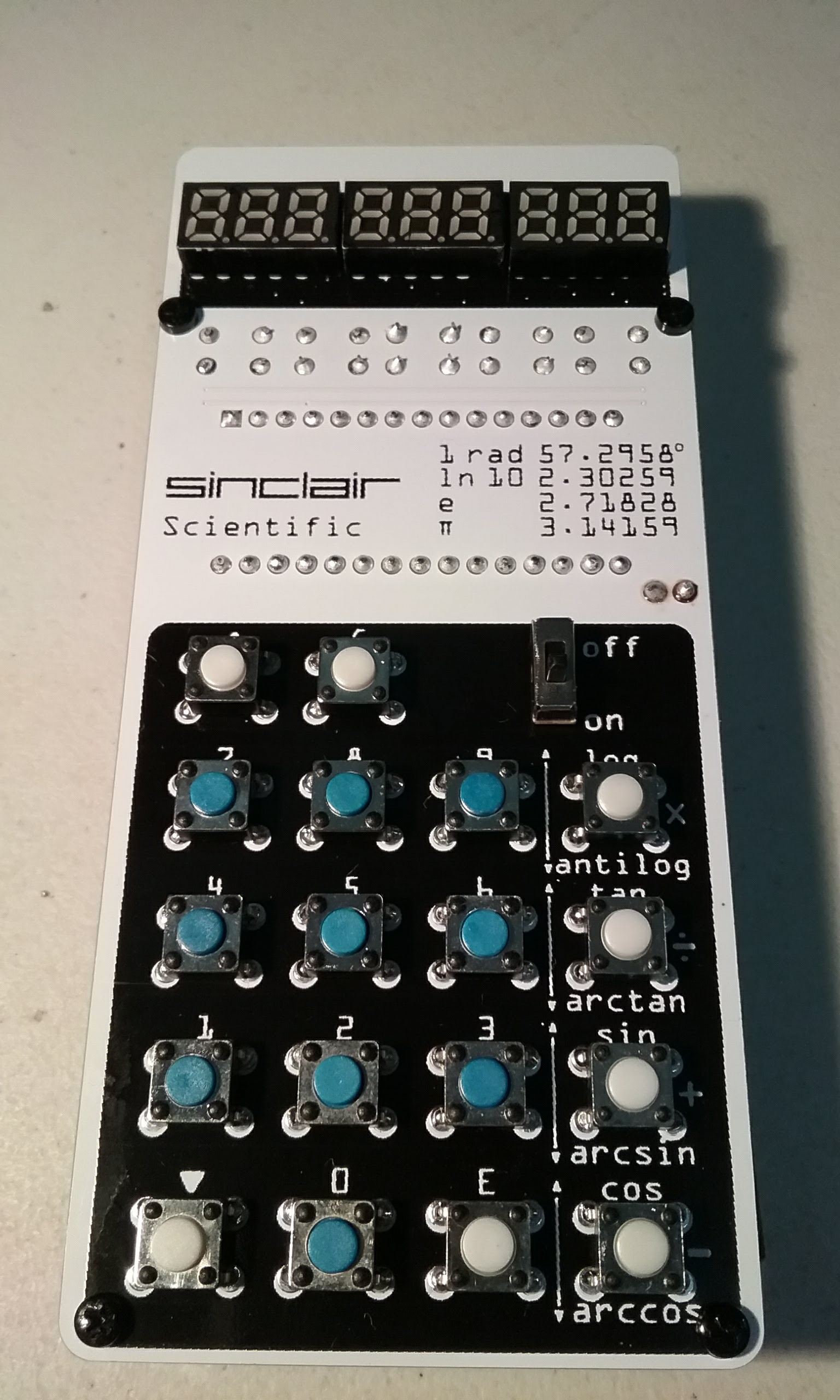
Time to power the board up. At this point it does not have a battery pack, so it is connected to the computer through the USB port. The display diagnostic test is entered by pressing 0 while the power is connected. Press 8 while the 888888888 are displayed to show a longer test. While connected through the USB port, the board will be always powered up and the power switch does nothing except for disconnecting the batteries from the Arduino. If you have a newer version of the calculator sketch, it can be uploaded at this point.
Flip the board over and trim the power switch legs.
The board will look like this at this point, time to clean it.
Using a cotton swab moistened in the appropriate solvent, clean the flux. A solder with water based flux was used here so cleanup was easy. Keep the cleaning fluid from entering the buttons.
Flip the board and clean the front.
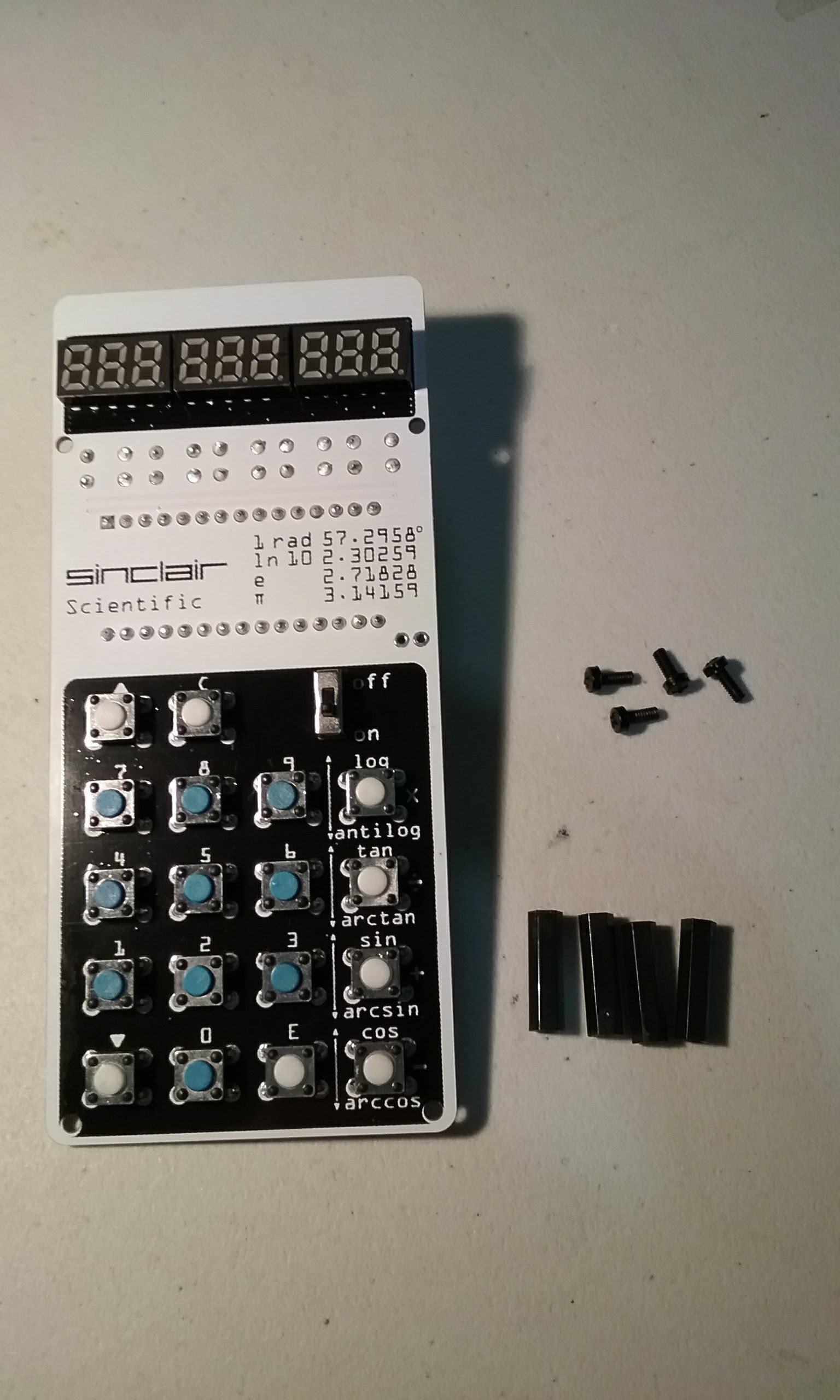
Time to install the M2 x 15mm standoffs. Hand tighten. Do not overtighten or the threads may strip.
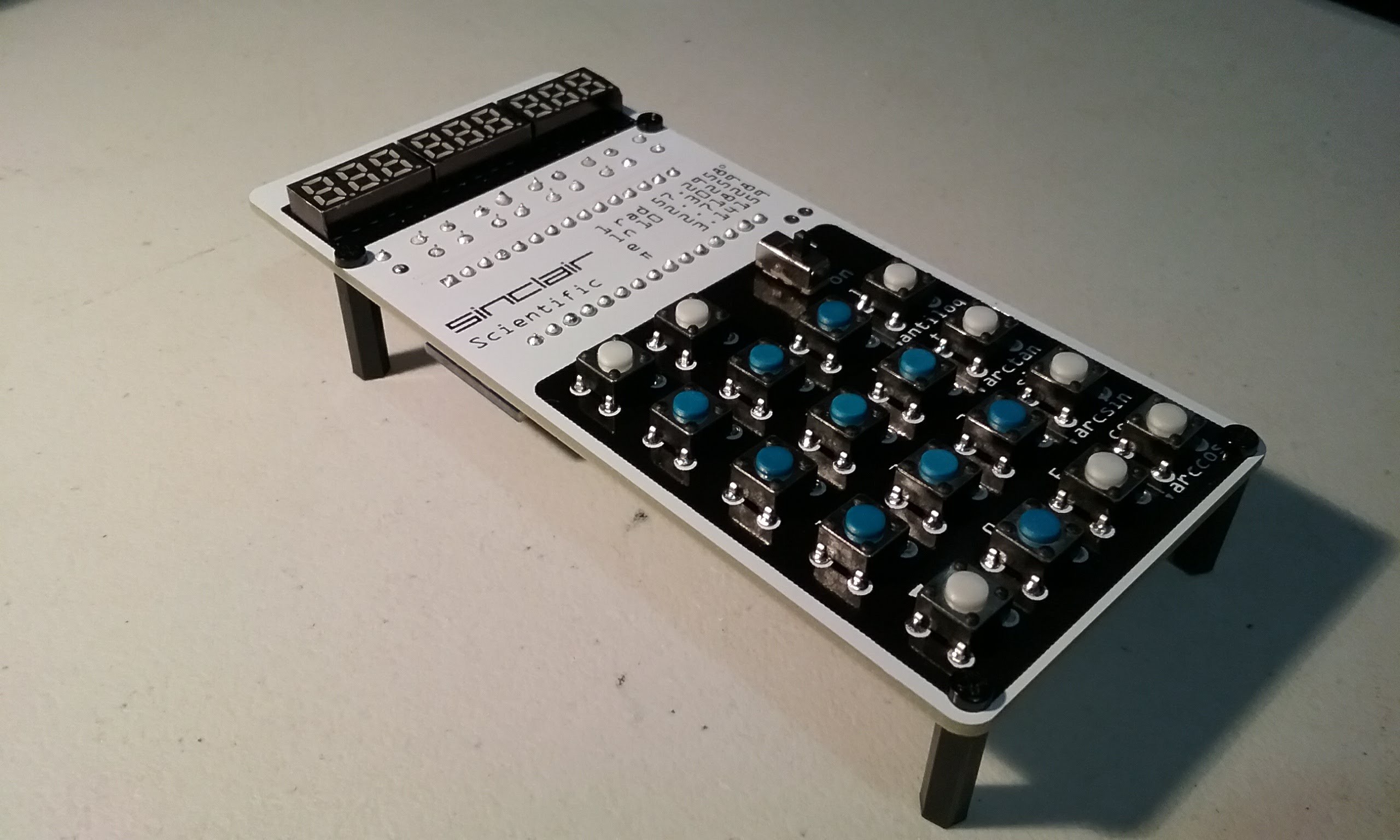
The board is now standing on its own legs...
Time to work on the battery pack.
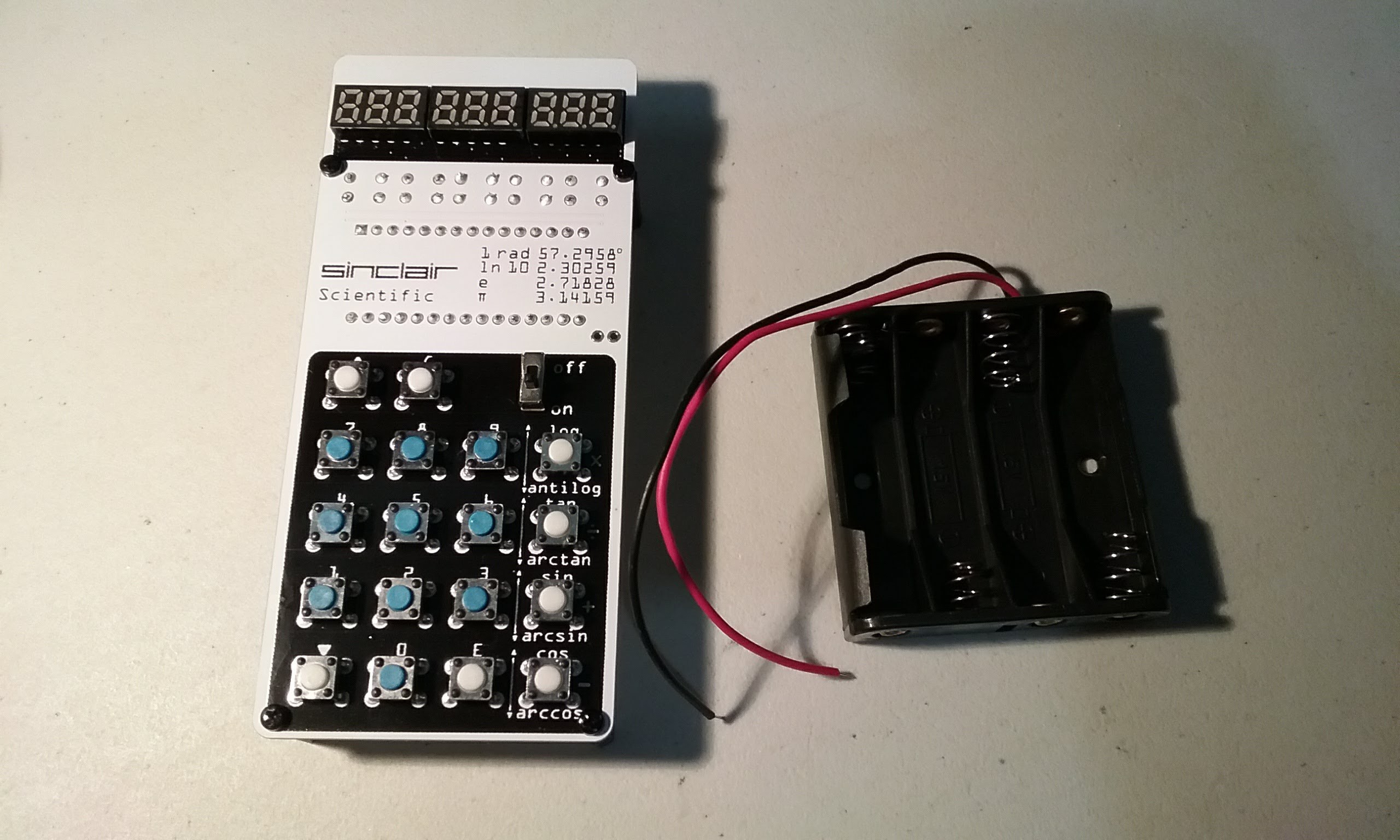
Place the battery pack in its place and trim the leads.
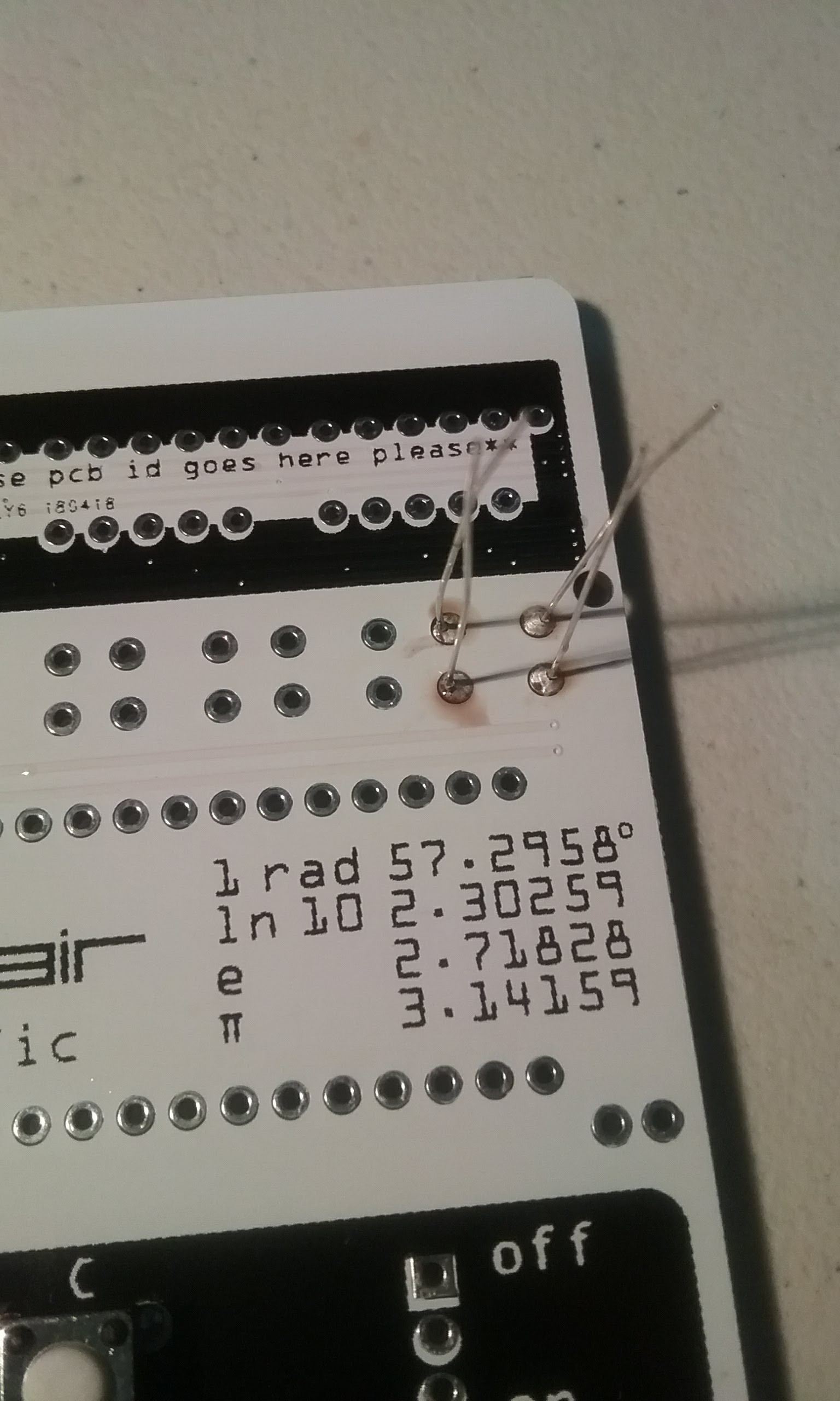
I prefer to use the soldering iron to burn the insulation off and deal with cleaning the soldering tip than nicking the thin wires. After the wires have been exposed, lightly tin them.
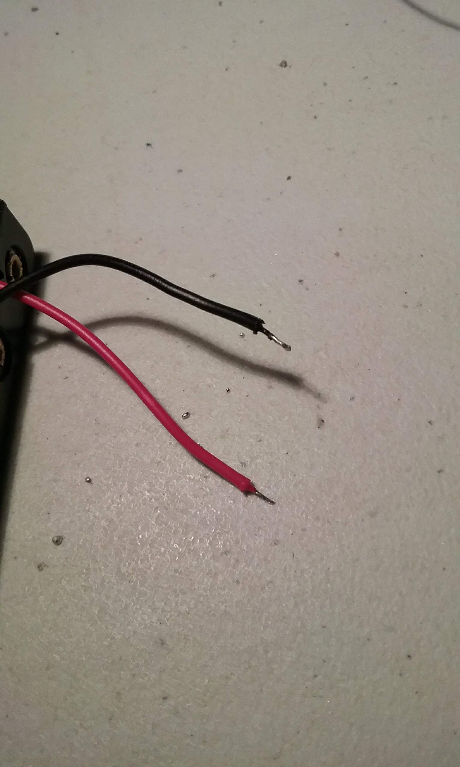
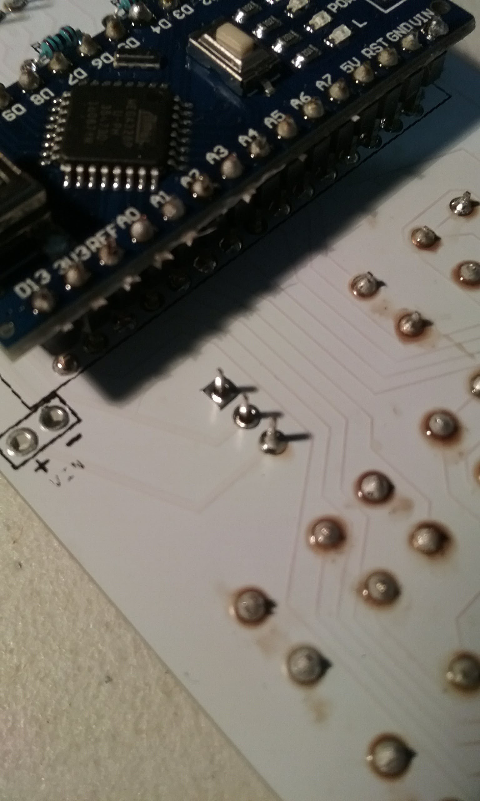
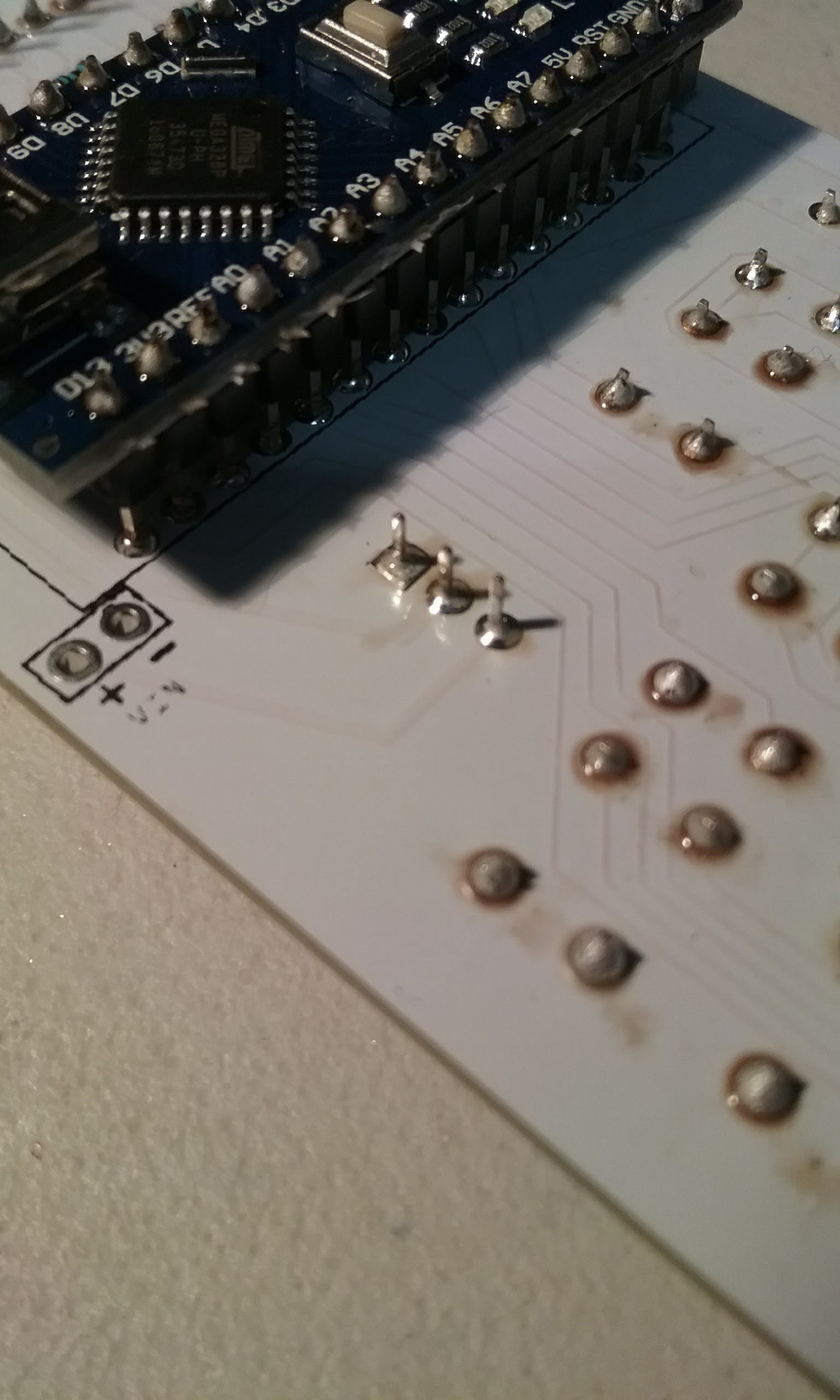
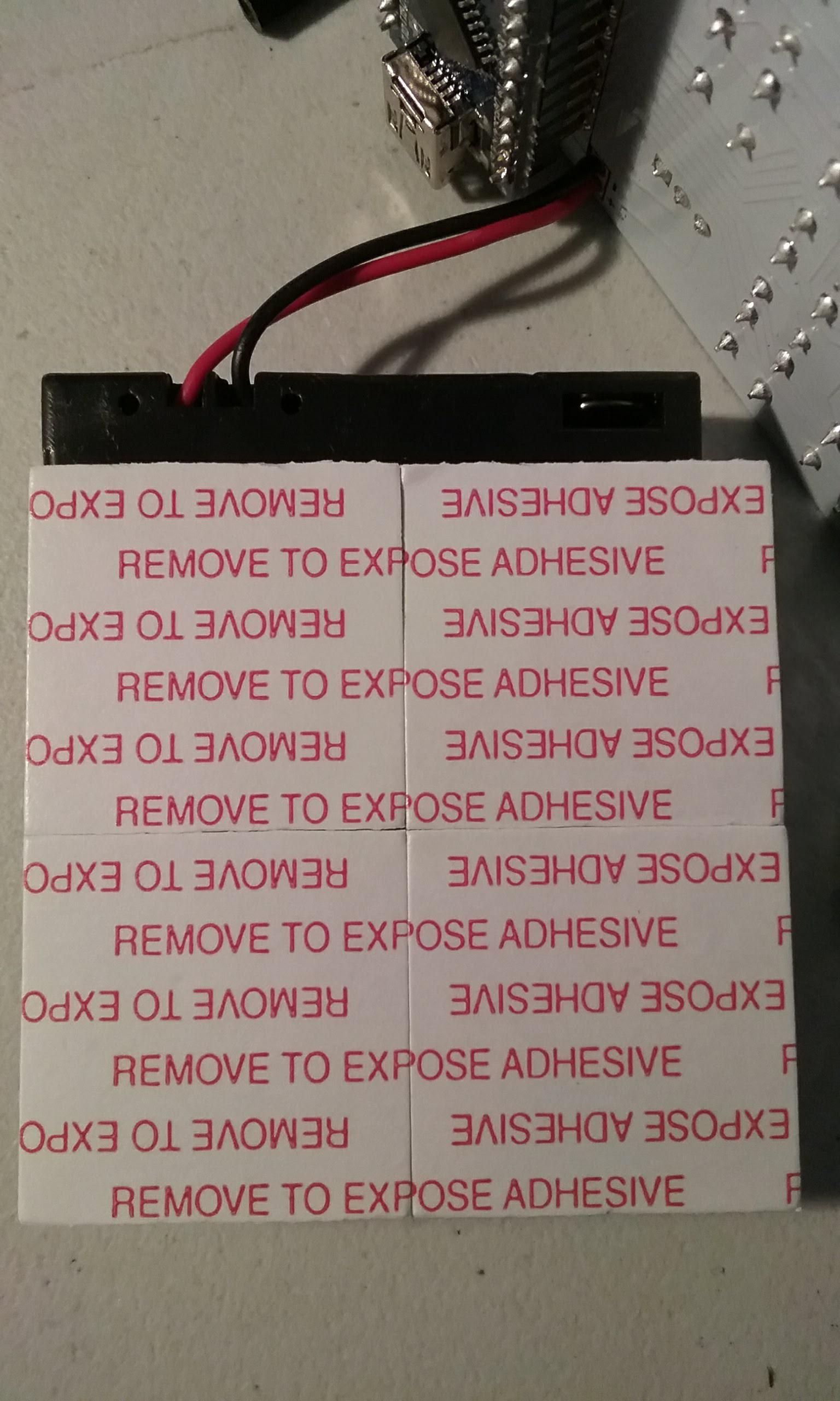
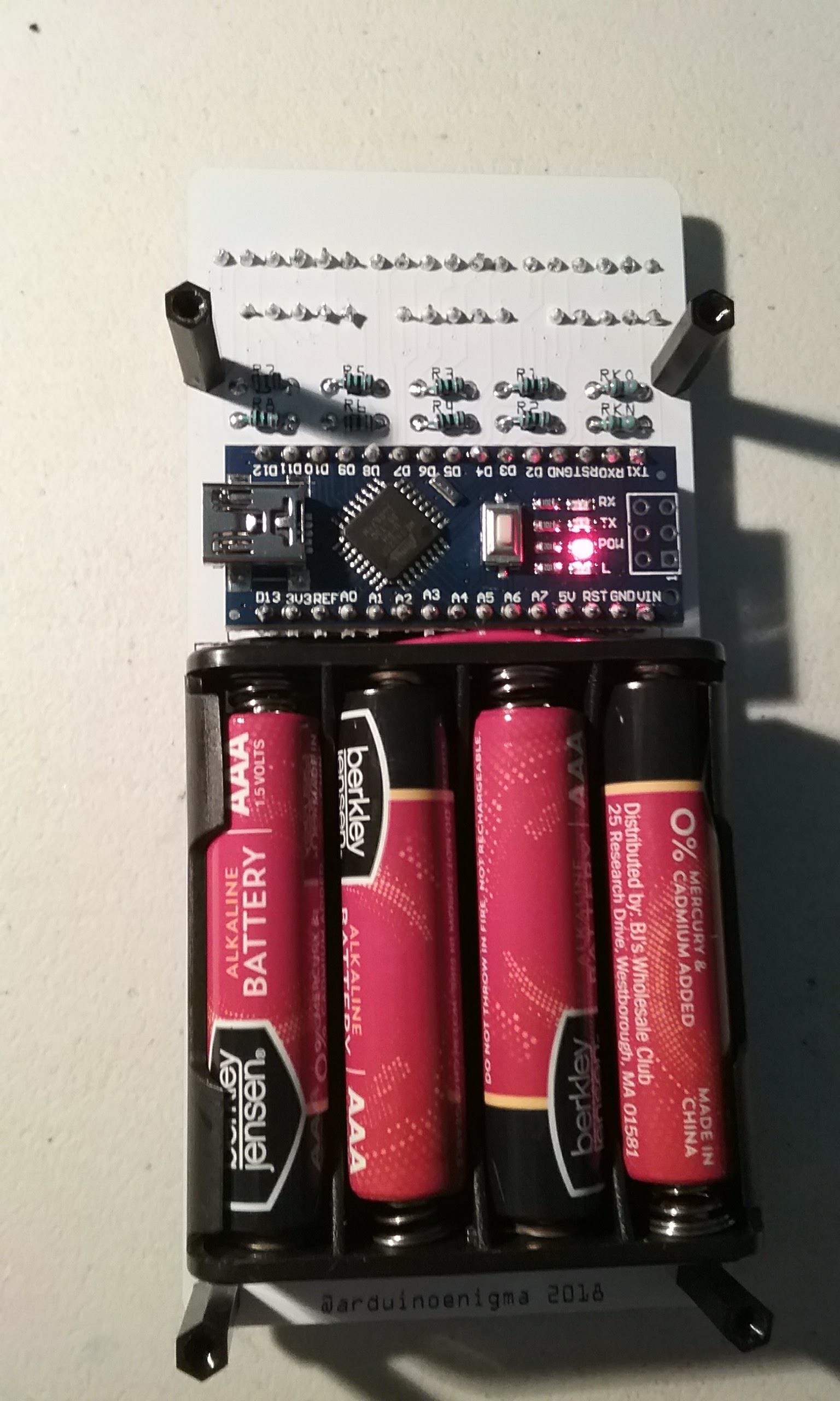
Insert the red lead (outside wire on the battery pack) on the outside hole (marked +) of the header. Black (inside wire on the battery pack) goes on the inside hole (marked -)
Measure the double side sticky tape, trim to size.
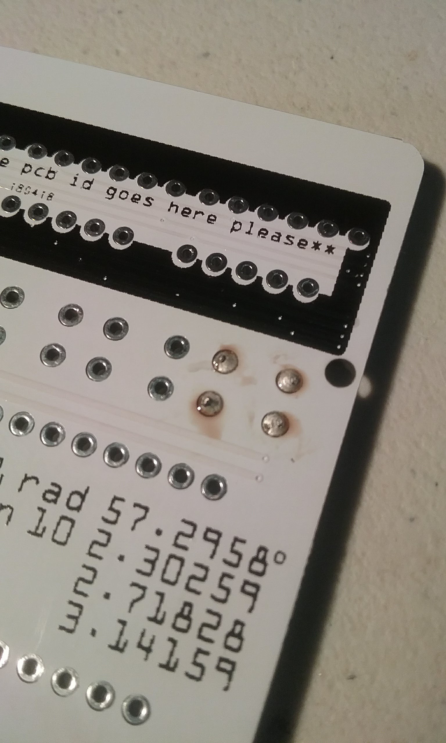
Watch the exposed wire at the bottom of the battery pack, if it touches the top pins on the bottom row of buttons, a digit will light up. Insulate or align so it does not touch the buttons.
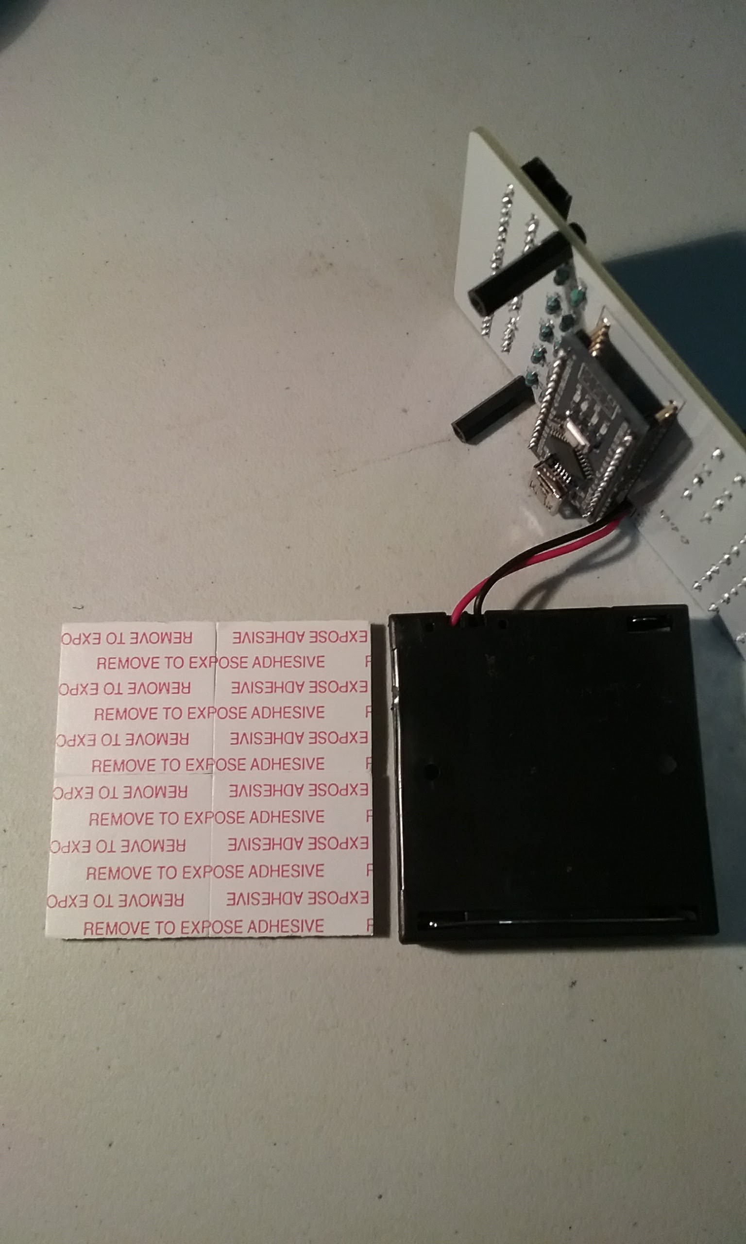
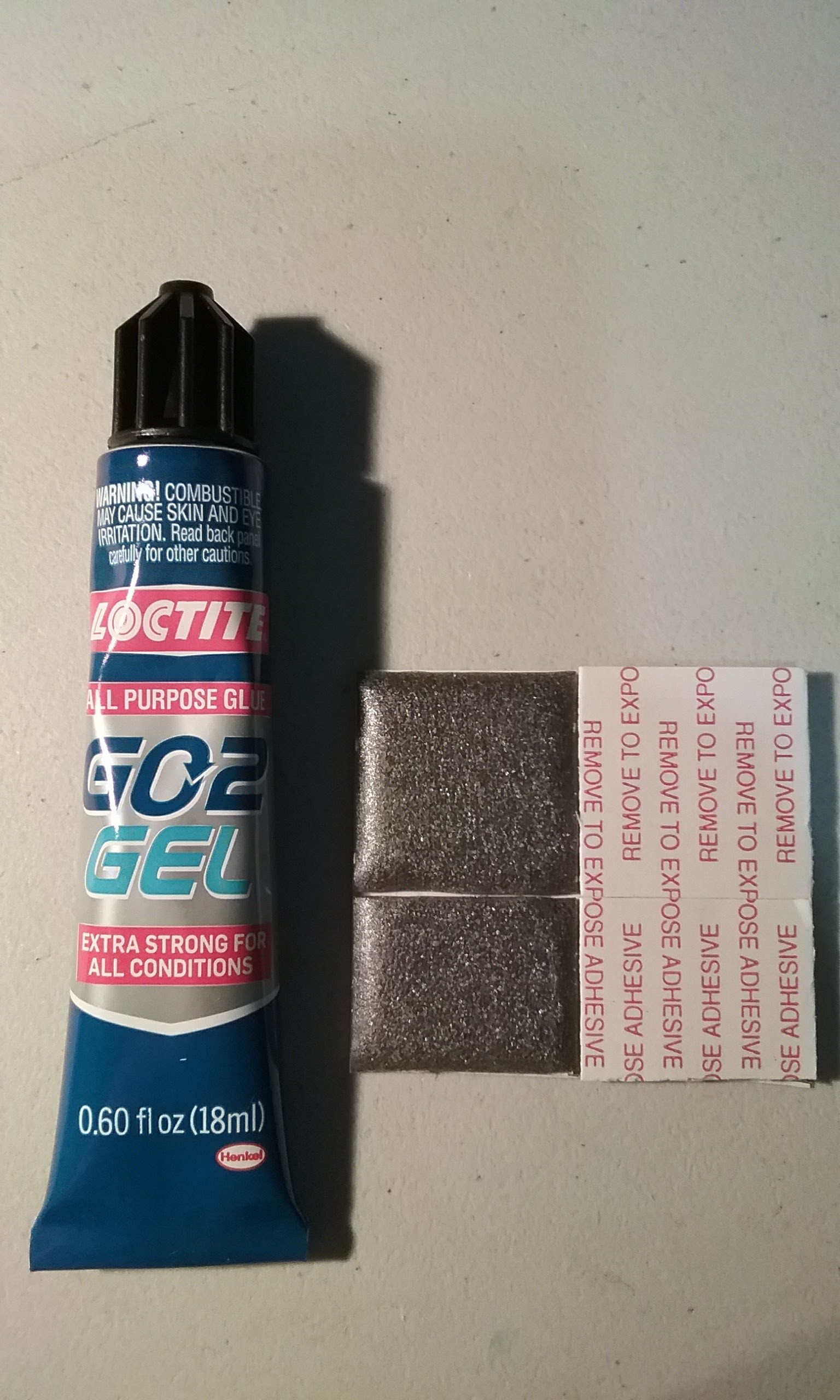
The excess on the right needs to be trimmed off.
Expose the adhesive on the strips. We will be using Go2 Gel to glue them down.
With a sharp object, pierce the adhesive strip. The idea here is to have a path for the glue to get inside the foam middle layer.
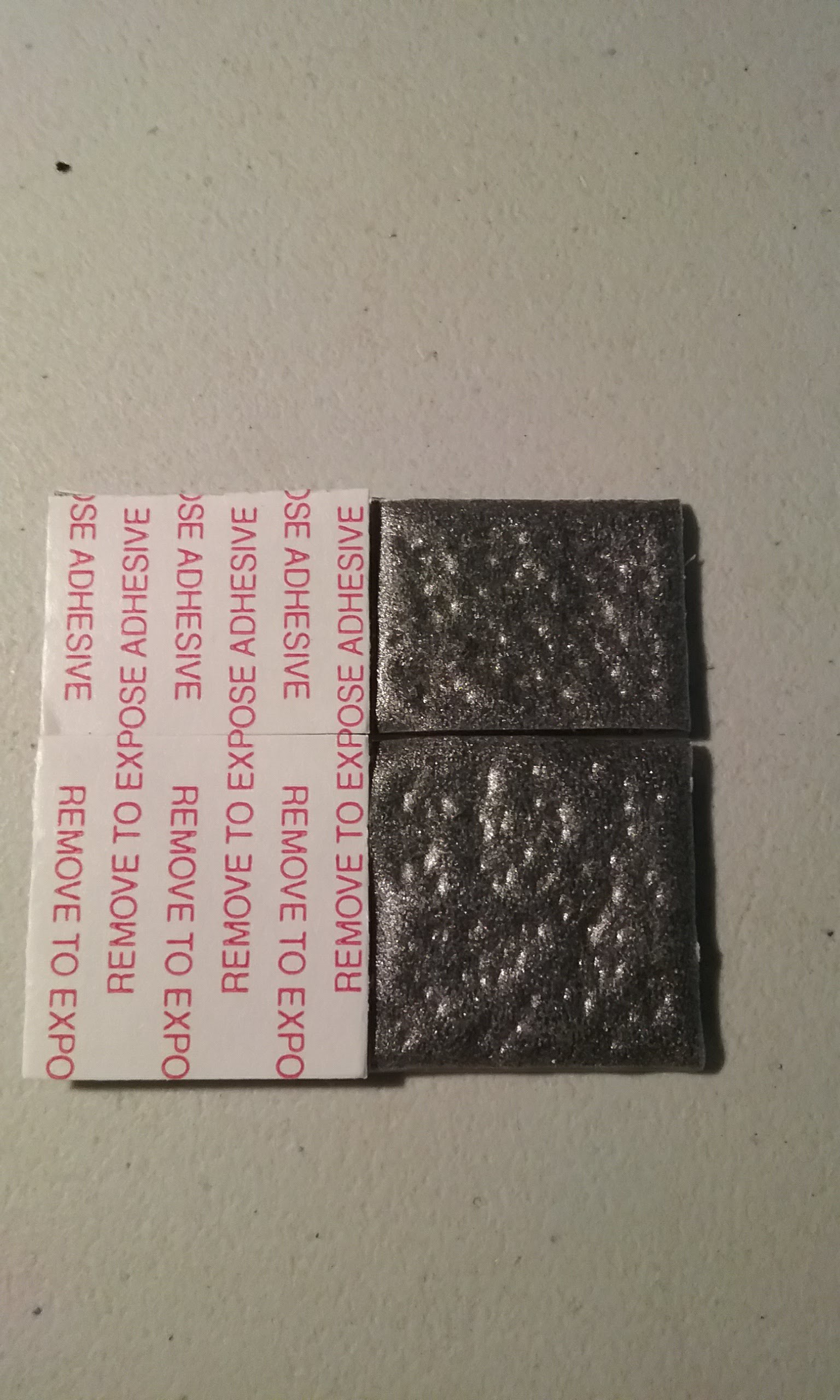
Put glue on the adhesive strip.
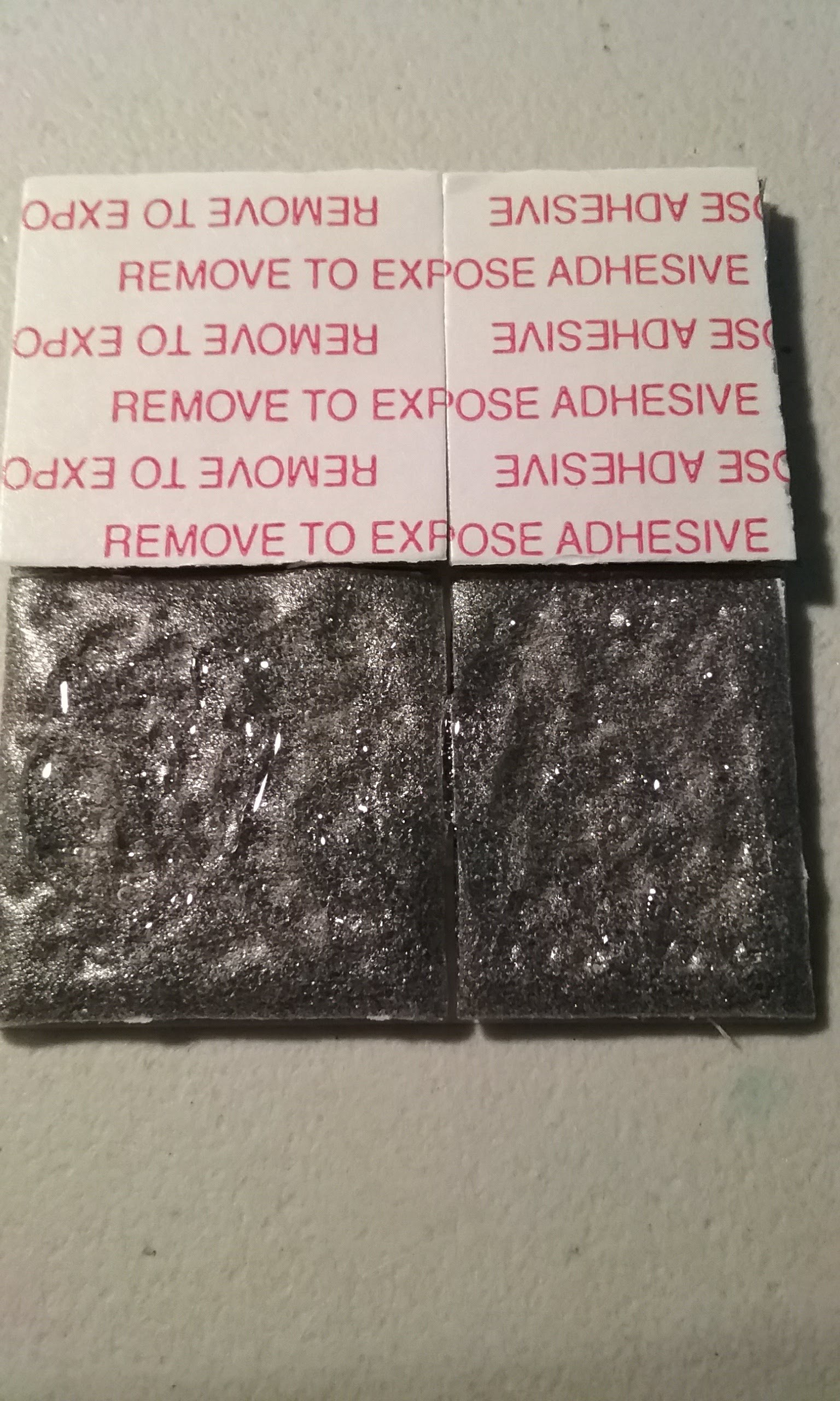
And stick it to the battery pack. Expose the other side of the adhesive strip and perforate. Lay a thicker layer of glue on this side of the tape and glue the battery pack to the PCB.
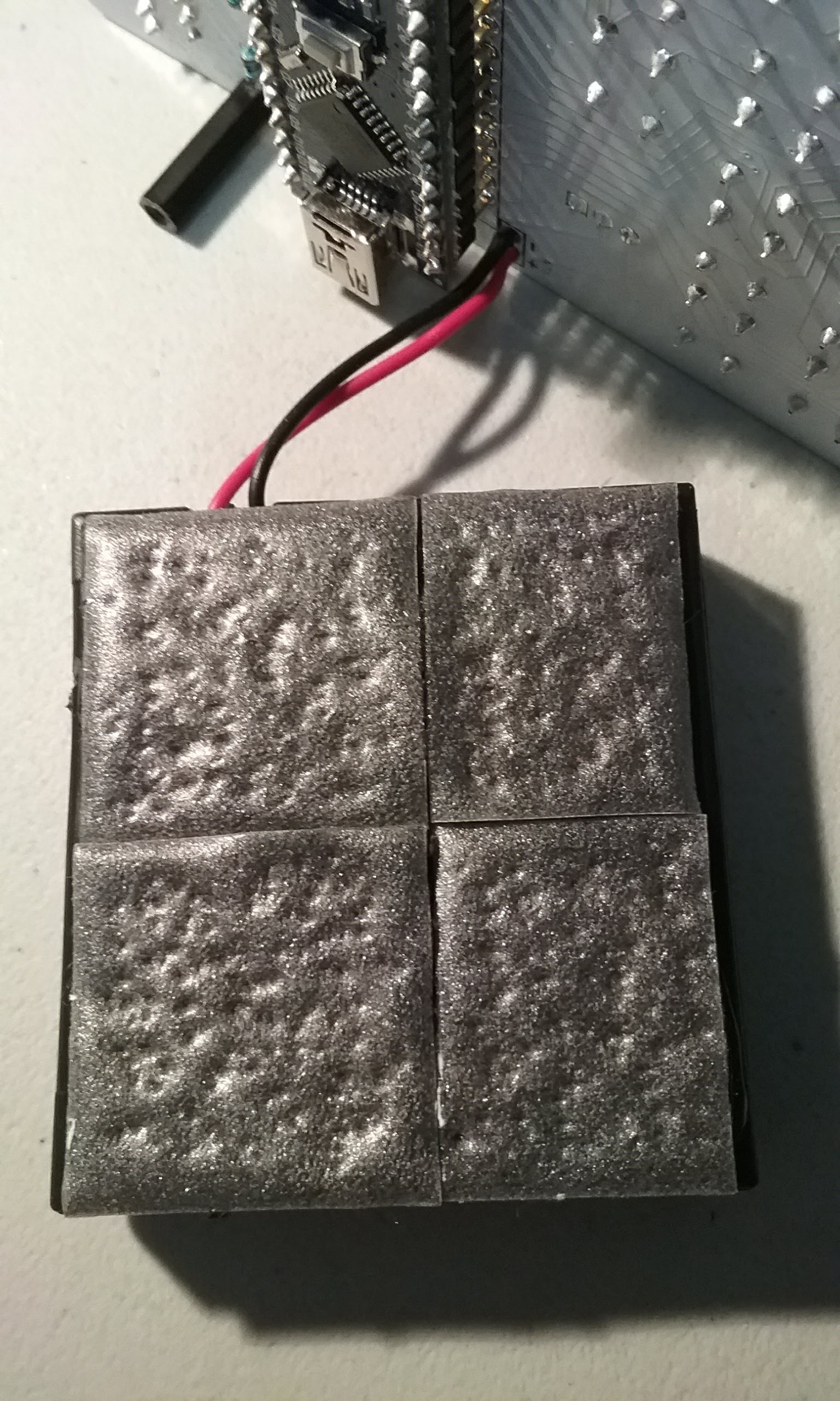
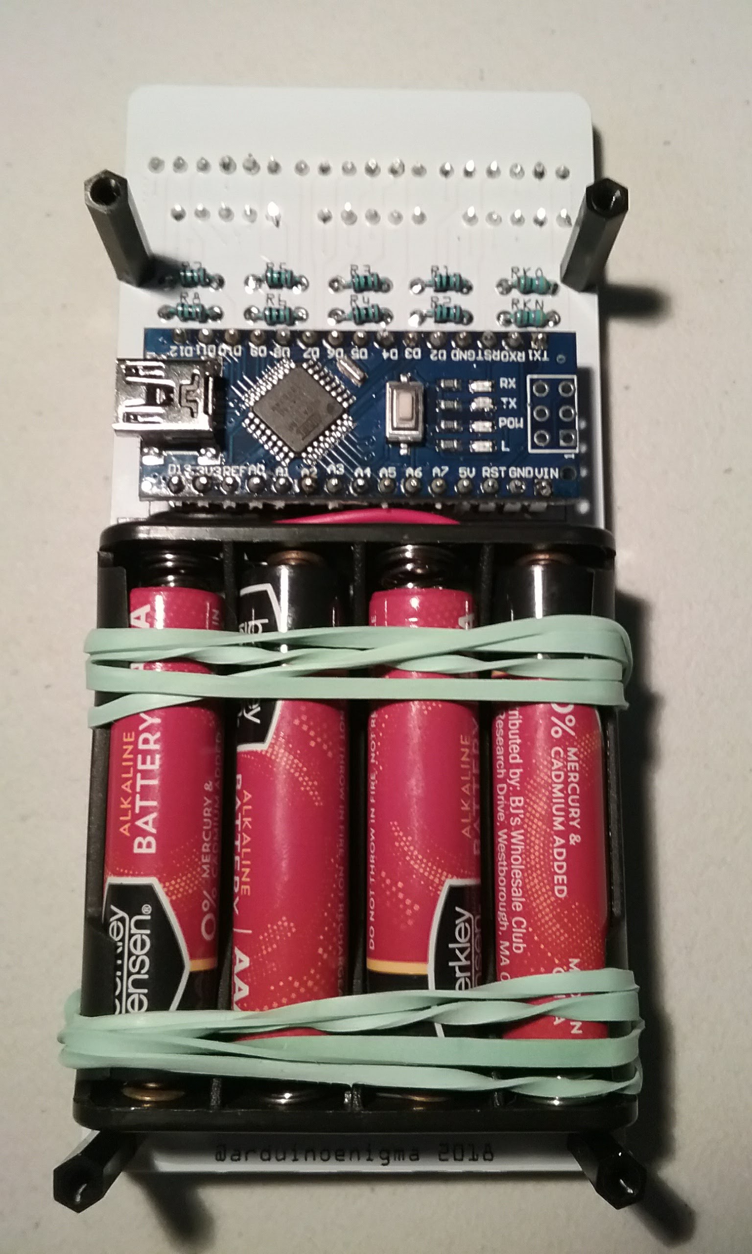
Install the batteries at this step.
And use rubber bands to secure the battery pack. Watch for that bottom wire on the battery pack touching the buttons. Move the battery pack down if it happens.
Keep everything like this for 24 hours to allow the glue to cure.
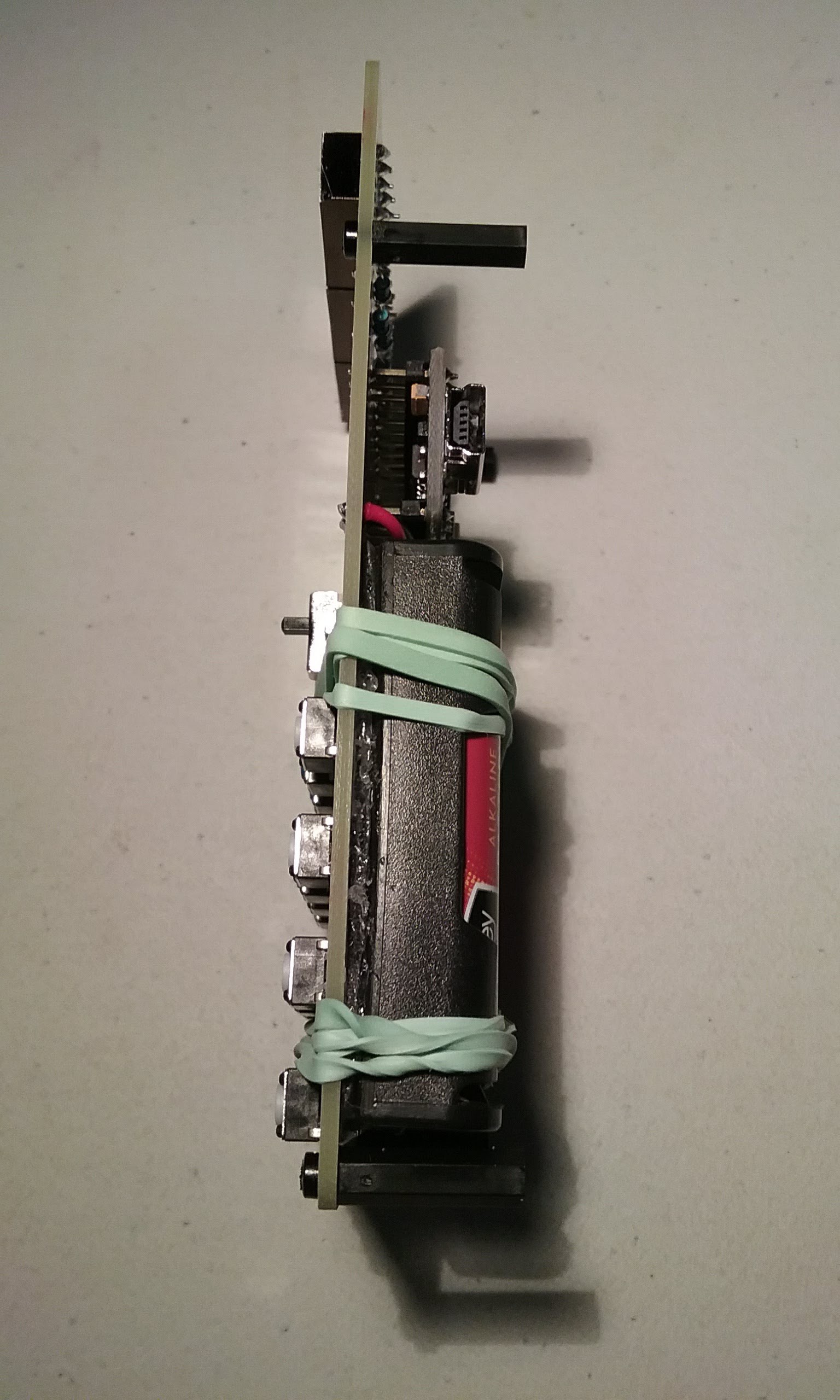
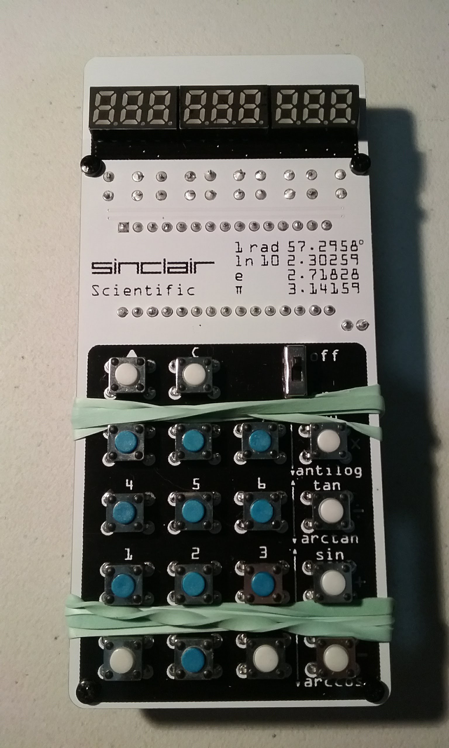
The rubber bands will keep the battery pack from falling until the glue sets. The calculator can be used at this point.
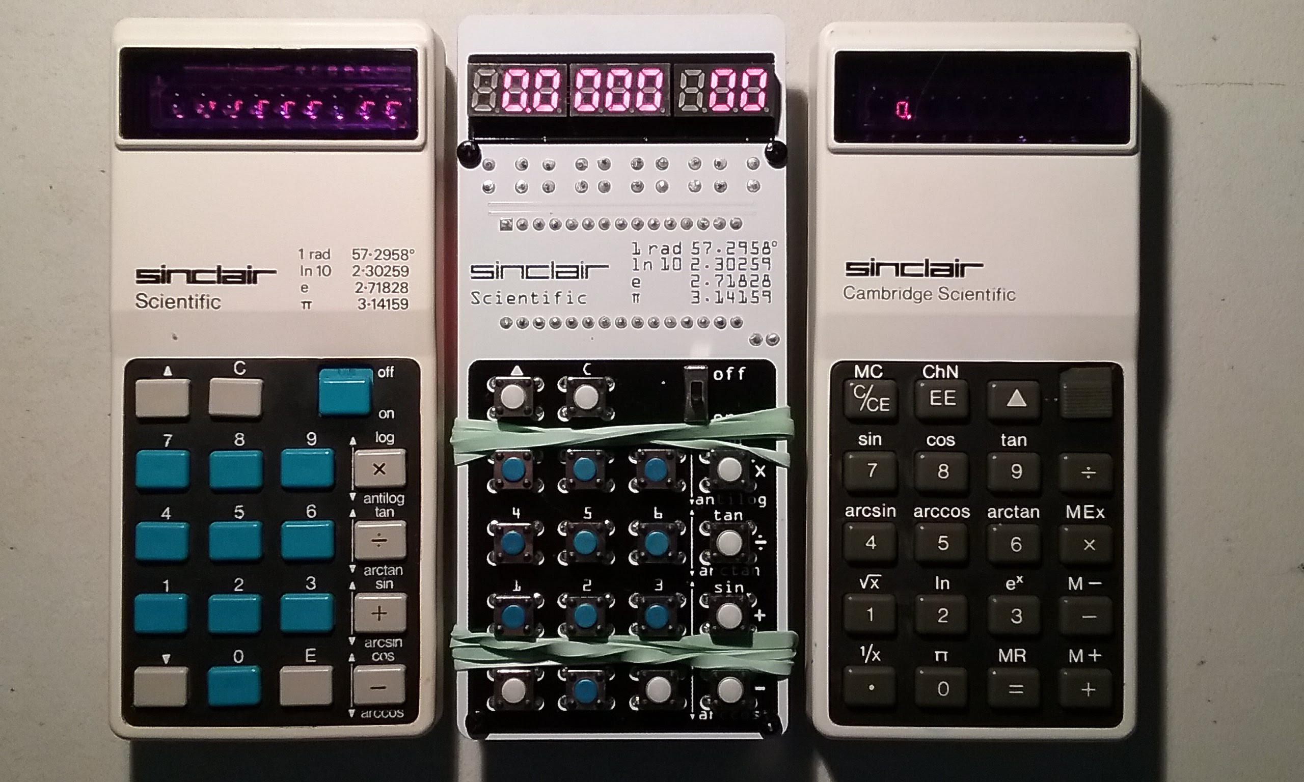
And a shot of the emulator in between two real ones.
After 24 hours, remove the rubber bands.
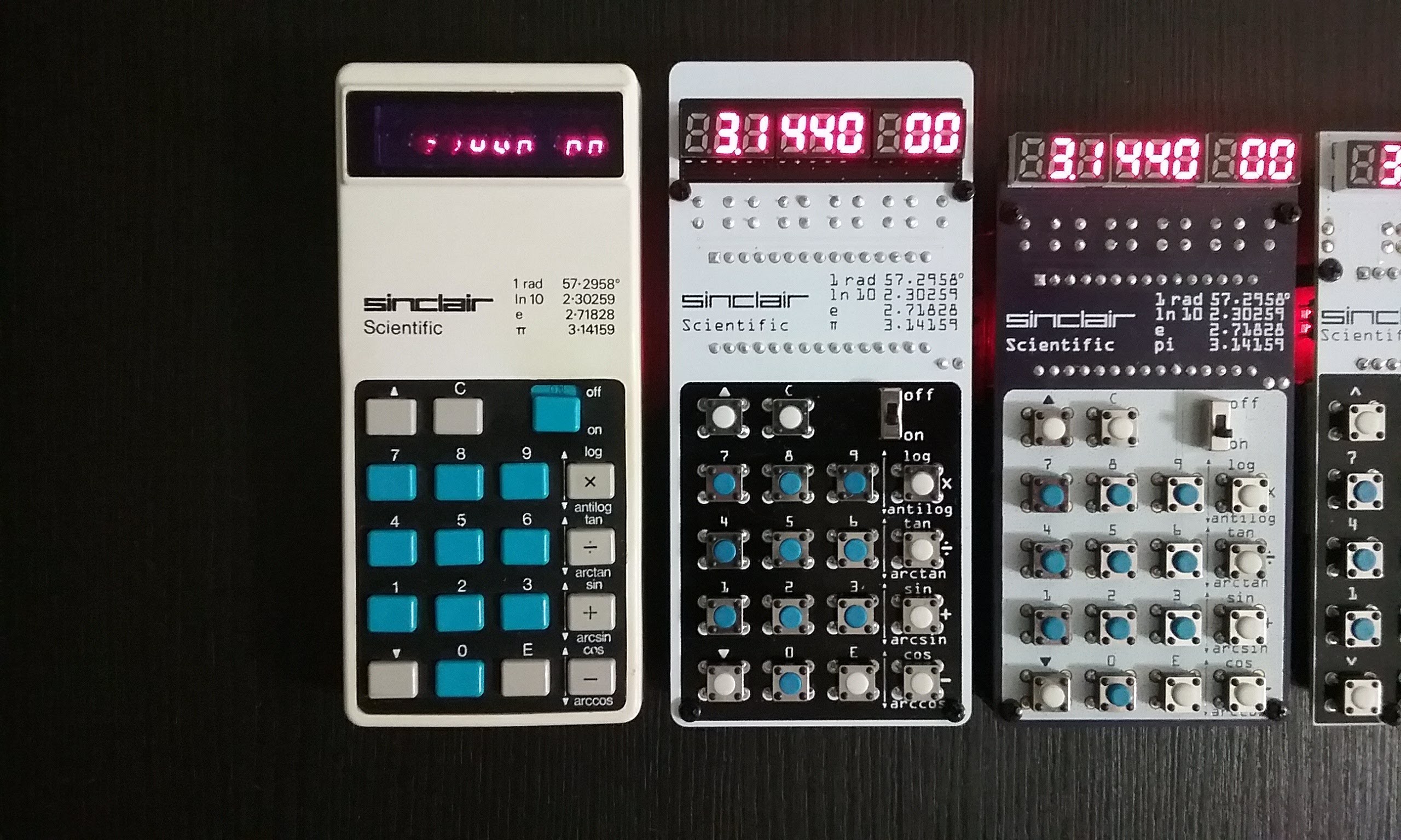
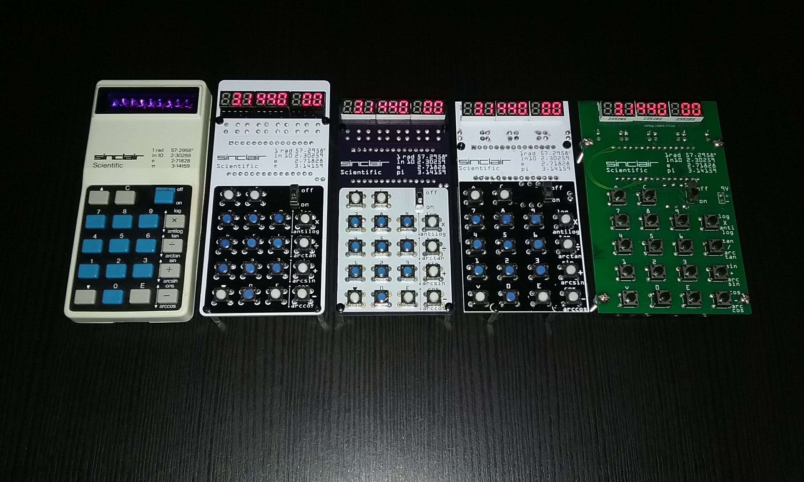
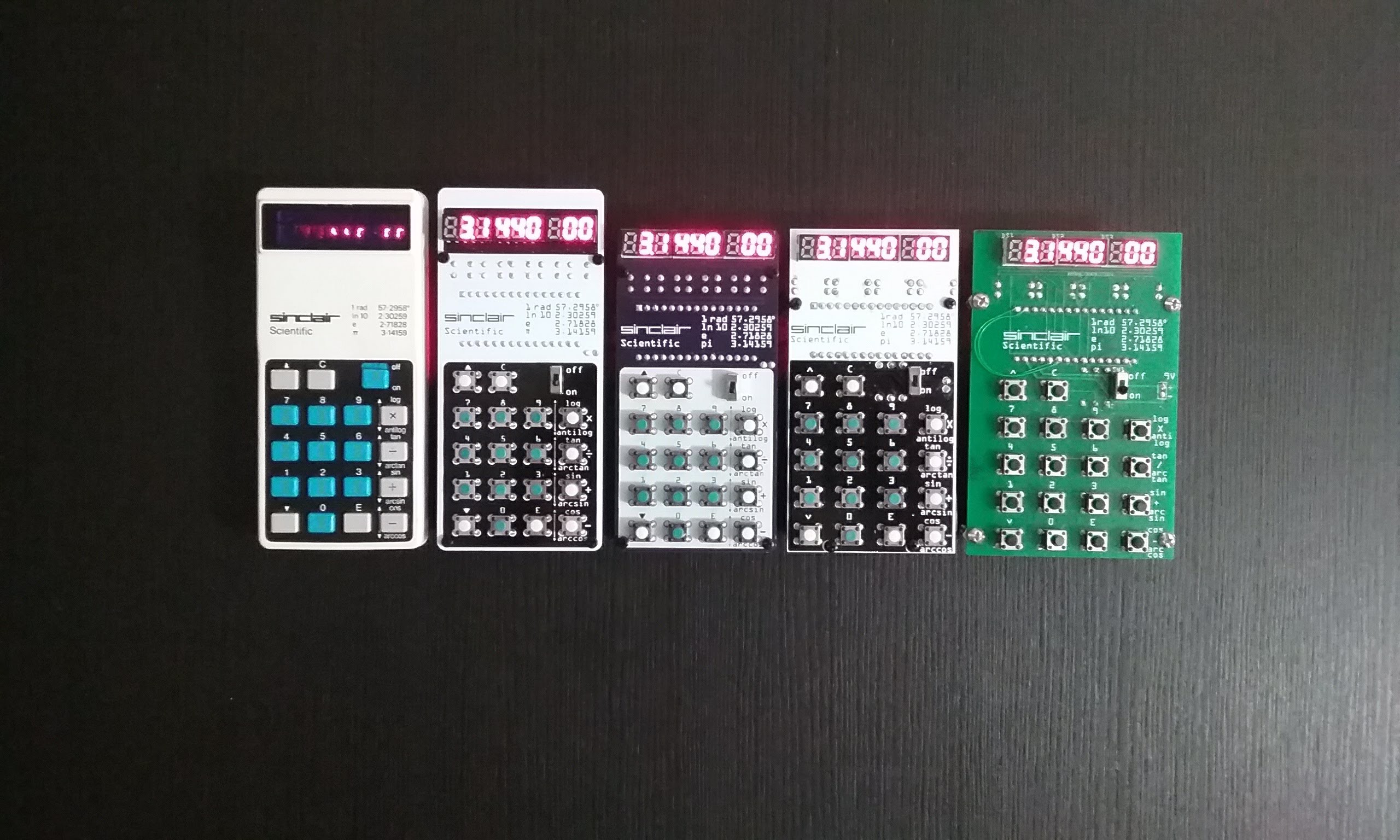
Here are some pictures of the finished product, next to the actual calculator for comparison.
And from right to left: V1, V2 (a resized V1), V5 (accurate keyboard circuit), V6
Discussions
Become a Hackaday.io Member
Create an account to leave a comment. Already have an account? Log In.