 Rainer
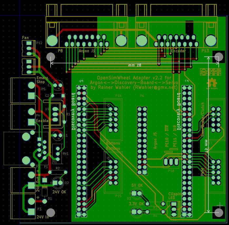
This board is used to connect all required modules with each other in a simple way. It connects the Argon servo controller with the encoder on the servo motor (i.e.Mige) and the Discovery Board from ST. The wiring and whole idea of the project comes from the Open Sim Wheel project, which uses industrial servo motors to build a force-feedback wheel for car games.
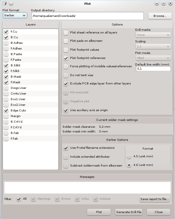
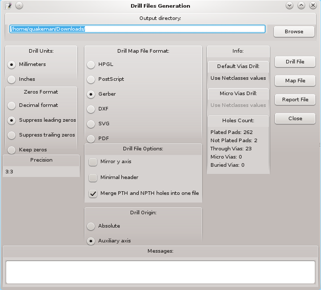
The schematic, layout and 3d view were created in KiCad.
I attached the original source files to this project site and all components could be sourced by Reichelt (Supplier in Germany) where i created a basket for all parts.
Optional voltage regulator for external fans
There is an optional voltage regulator on board which could power up to two external fans. The voltage can be regulated between ~1,5V and ~22V with help of the potentiometer and is powered from the main 24V power supply. So if external fans should be used the total power consumption of the Argon and all attached fans should be considered for the power supply.
Connectors P10 and P12 have a pinout for typical 3 pin connectors of pc fans. But also normal fans with 2 pin connector should work. In case of pc fans the voltage should be set to ~12V. With help of the regulated voltage it is possible to adjust the noise level and air flow of the attached fans.
Assignment of all connectors
| Description | Connection type | I/O | Function |
| P1 | 8 pin RJ45 | Out | Emergency stop and enable wire to Argon at J2.2 |
| P2 | 2 pin female header | Out | 24V for Argon at J3 |
| P3 | 2 pin female header | In | 24V from power supply |
| P4 | 2 pin female header | In | Argon enable contact (shorted to enable) |
| P5 | 2 pin female header | In | Emergency stop switch (shorted to work normally) |
| P6 | 26 pin header | Out | PWM and DIR control signals to Argon at J5 |
| P7 | 50 pin female header | In/Out | Control signals from Discovery Board |
| P8 | 15 pin d-sub male | Out | Rotary encoder signals to Argon at J1 |
| P9 | 50 pin female header | In/Out | Control signals from Discovery Board |
| P10 | 3 pin header | Out | External fan 1 |
| P11 | 3 pin header | Out | External clipping LED |
| P12 | 3 pin header | Out | External fan 1 |
| P13 | 15 pin d-sub female | In | Rotary encoder signals from servo motor |
| P14 | 10 pin header | In | Optional 8 external buttons |
| P15 | 10 pin header | In | Optional 8 external buttons |
| P16 | 10 pin header | Out | All possible PWM signals |
| P17 | 10 pin header | In | Analogue potentiometer (brake, clutch, gas) |
| P18 | 3 pin jumper | - | Jumper to select PE10 or PE11 for DIR signal |
Pin assignment of P8 for rotary encoder
| Pin | Function |
| 1 | Motor ground |
| 2 | +5V |
| 3 | 0V |
| 4 | CH A+ |
| 5 | CH B+ |
| 6 | CH Z+ |
| 7 | CH A- |
| 8 | CH B- |
| 9 | CH Z- |
| 10 | CH U+ |
| 11 | CH V+ |
| 12 | CH W+ |
| 13 | not connected |
| 14 | not connected |
| 15 | not connected |
 Ben Mo
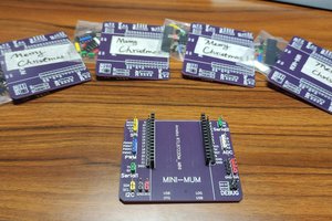
 SimonXi
 CaptMcAllister