Close
0%
0%

BluBEAM - a scanning laser microscope

Imaging at micrometer resolution using a Blu-ray drive

Similar projects worth following
Confocal microscopy is a standard tool (especially in biology and the life sciences) to image at the diffraction limit.
If you have got a microscope at home, you probably know that reaching the theoretical resolution of about 200nm isn't going to work. High-end research-grade machines are needed for that.

We are circumventing the problem by building a scanning confocal microscope from easily available components, such as a Blu-ray drive, a microcontroller, some steppers and a micro-positioner. Once finished, we will be able to take pictures of things at micrometer resolution.

Let's start with what this project is about:

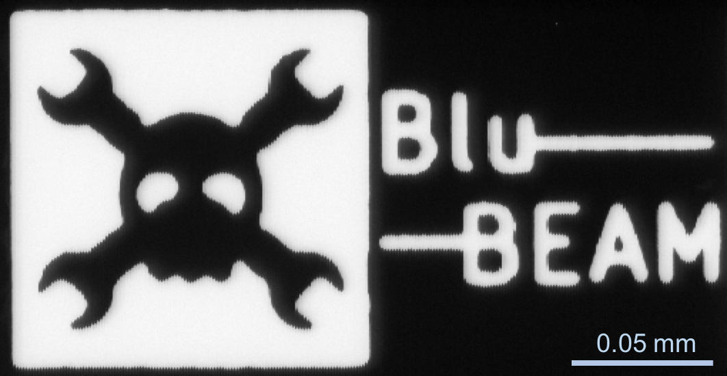
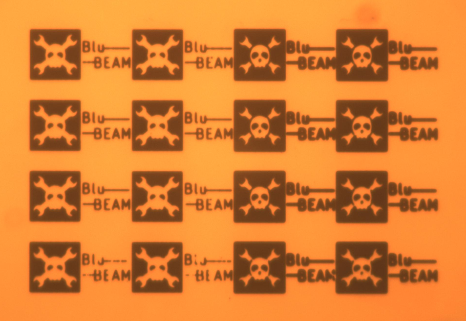
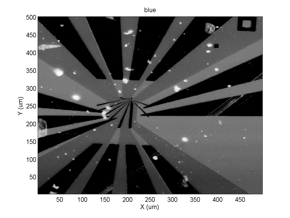
It's about imaging objects at the micrometer scale, using "off-the-shelf" components (quite literally sometimes off the things-I-took-apart-shelf) and a fair amount of reverse-engineering and hacking.

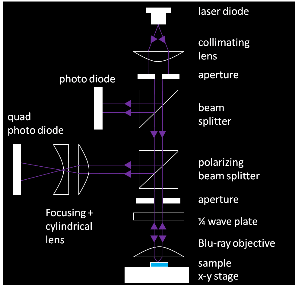
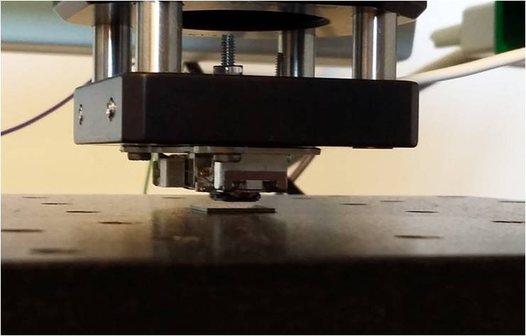
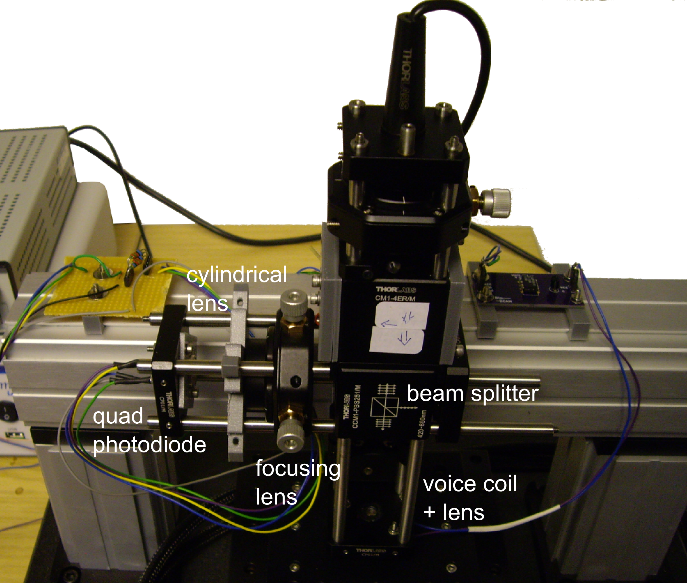
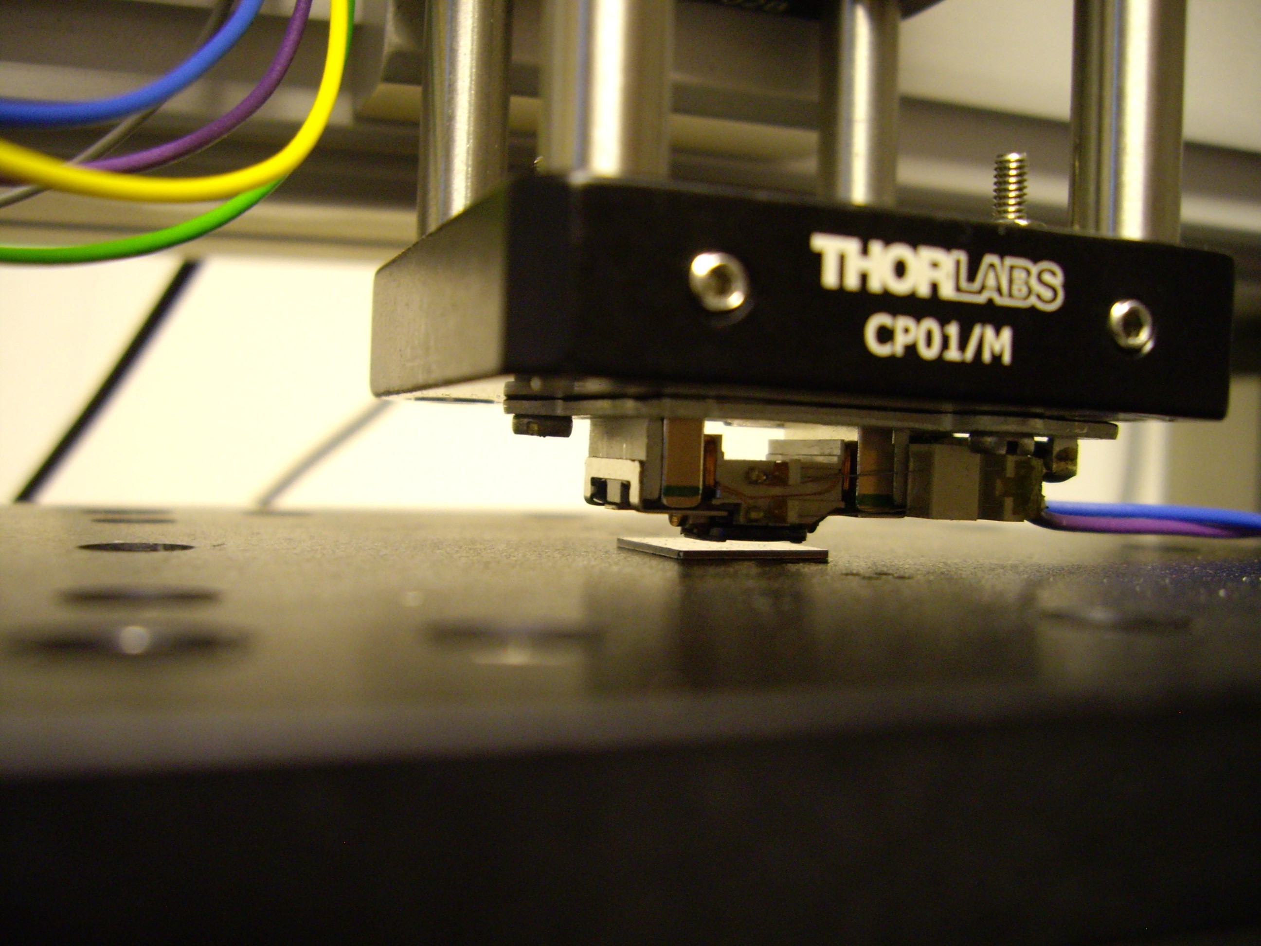
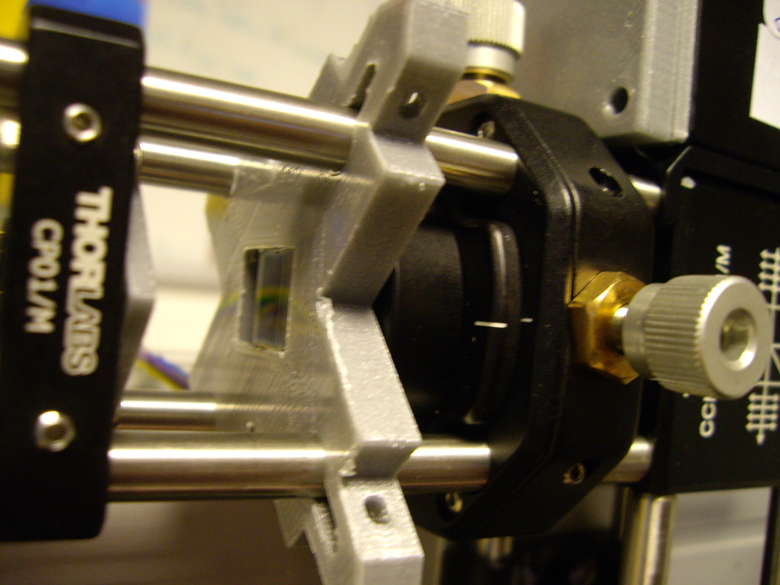
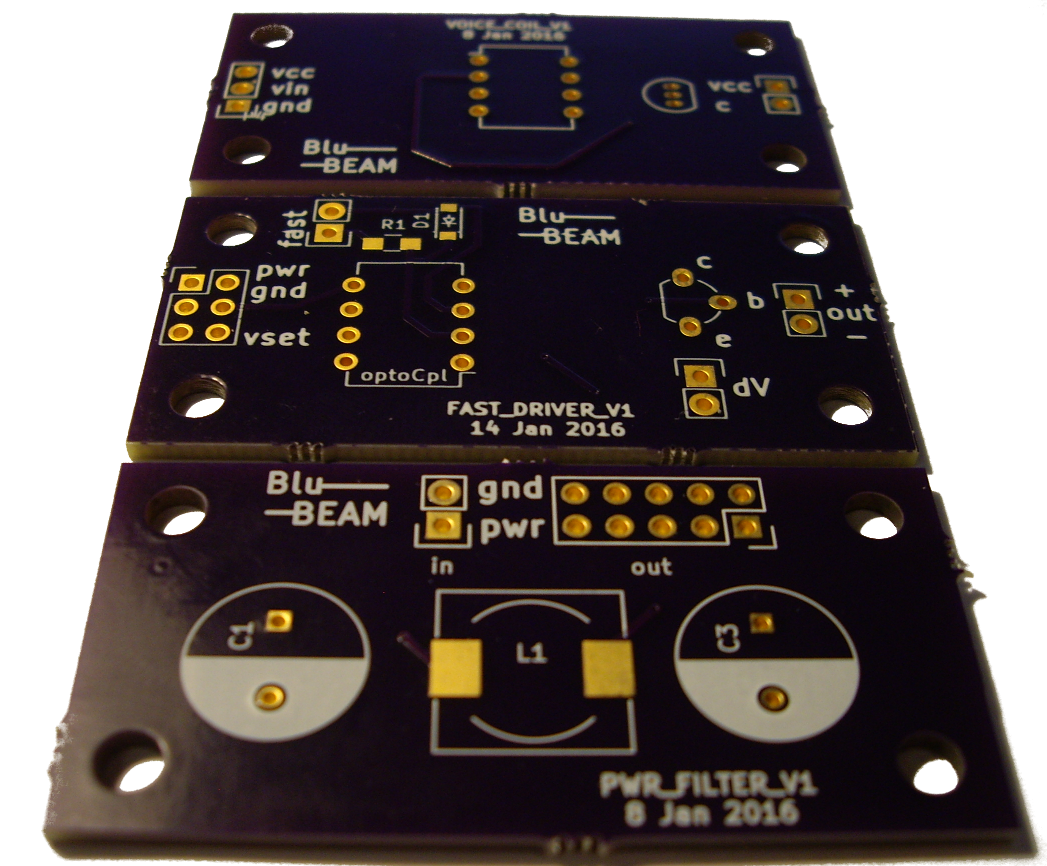
The heart of the microscope will be a Blu-Ray drive read head. It's an incredible piece of engineering, and the optical/electronic components that we need for our microscope are already in there. The challenge will be to get access to the components, to drive/read them at will, and to integrate the read head with a precision stage.

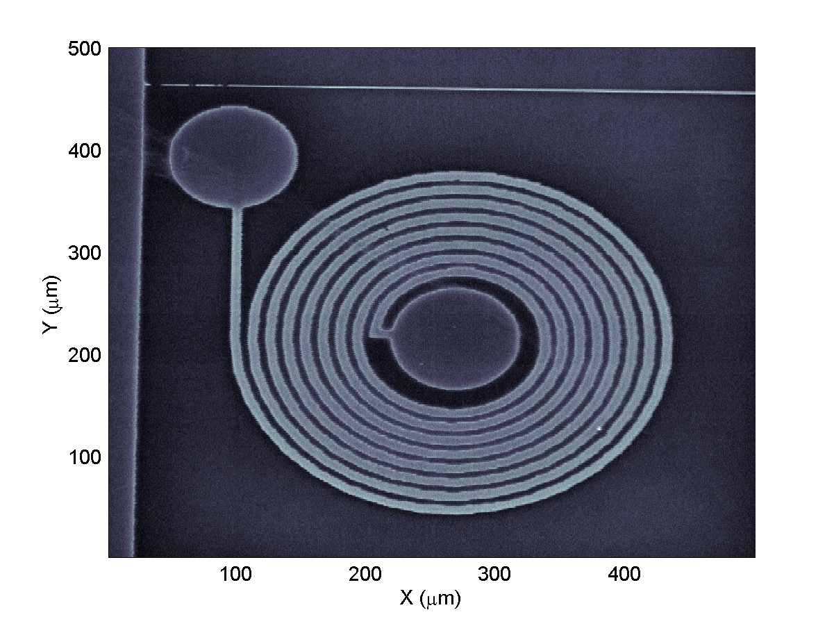
The scan area will initially be limited to 1mm in one direction and a few mm in the other.

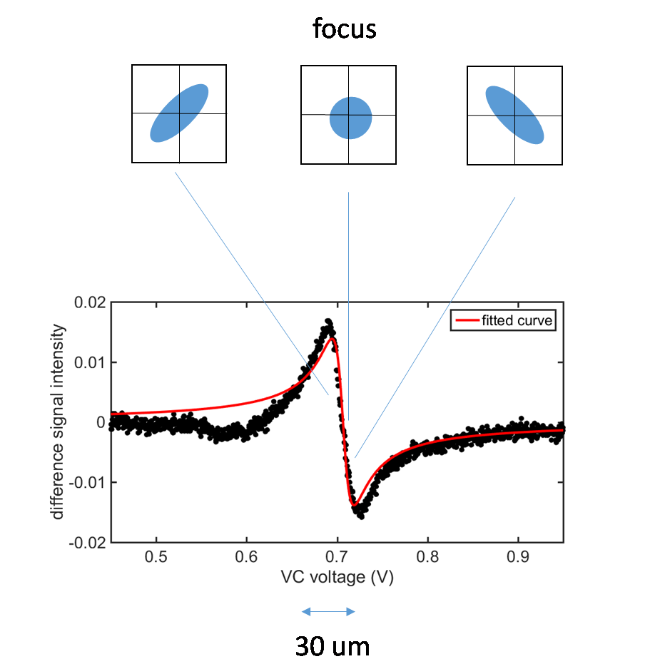
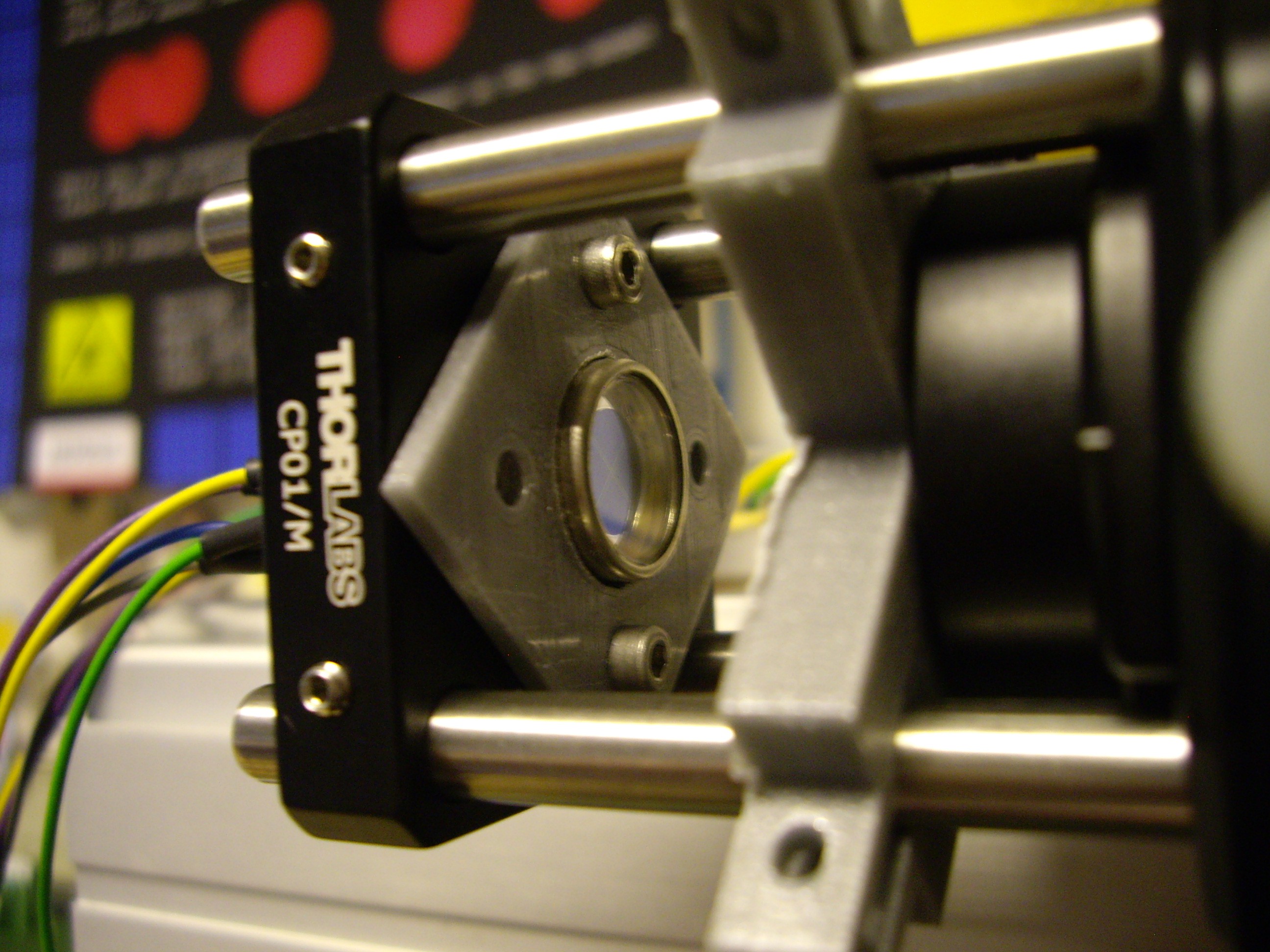
For focusing we will use the quad-photodiode built into the read head.

More detail on all of this will follow in the project logs, as and when we achieve them.

FastDriver.kicad_pcb

KiCad PCB file for the laser driver

kicad_pcb - 45.46 kB - 02/12/2016 at 18:16

Download

PowerLineFilters_v1.kicad_pcb

KiCad PCB file for the power line filter

kicad_pcb - 27.33 kB - 02/12/2016 at 18:15

Download

voice_coil_driver.kicad_pcb

KiCad PCB file for the voice coil driver

kicad_pcb - 24.01 kB - 02/12/2016 at 18:14

Download

  • Hooray, we won!

    andreas.betz07/28/2016 at 10:21 1 comment

    BluBEAM has been selected as one of the winning projects in the Hackaday prize "citizen scientist" round!

    A big thank you for your support guys, and your great comments and questions.

  • Micro Jolly Wrencher

    Andrew Ferguson06/24/2016 at 10:59 1 comment

    Serious things have happened in our country (the U.K.) overnight, so we thought we would cheer ourselves up by imaging a lithographically fabricated familiar figure. The Jolly Wrencher was patterned with direct write laser lithography, which can reach a resolution of better that 1 um, and of course it is similarly imaged with our scanning laser beam, with similar resolution. The total width of the Wrencher field is 125 um, which is just less than the minimum track width you can order from OSH Park (150 um).

    It is pretty small, enjoy!

    And here is a more standard microscopy image (using a x5 objective), showing the full pattern that we fabricated. The metal film that has been patterned is gold (100 nm) with a chromium adhesion layer (10 nm) to a polished sapphire substrate.

  • Images: a spiral inductor

    Andrew Ferguson06/15/2016 at 12:33 2 comments

    Continuing with the desktop system, we have had fun taking some more images, using the violet laser. This time the sample is a planar microwave inductor that we had lying around. As you can see the inductor has 8 turns and a track width/separation of about 10 um. The circular pads are for wire-bonding to and the lighter regions are thin-film gold. By the way, do let us know if you have any good ideas for devices to image - an old integrated circuit with relatively big feature size might be interesting.

    In addition to the image, here is a cross-section through it (about half way up). The risers are about 1 um and, in the future, we will use these to profile the beam and see how close to the diffraction limit we get.

  • First image! Sub-micron resolution!

    andreas.betz06/14/2016 at 19:42 2 comments

    With focusing and stage movement in place, it was time to have a go at imaging something.
    So without further ado, I give you our first BluBEAM confocal micrograph!

    What is it though? Well, I'm not too sure myself, but it's some kind of old prototype transistor fabricated by the guys at the Microelectronics lab in Cambridge, UK. Black regions are definitely a metal layer, created by e-beam lithography.

    Anyway, the great news we get from this image is that we have a sub-micron resolution of about 680nm!
    Let's see how far we can get with this now...

  • Update: System overview & focusing

    andreas.betz06/14/2016 at 08:43 0 comments

    Further to the last post a little while ago, here's schematic overview of the system as it stands right now:

    We have two photo diodes now, a single one to measure the laser output power via a 50/50 beam splitter, and the quad photo diode for the astigmatic focusing. A second, polarizing beam splitter plus a quarter wave plate allows us to only receive light coming back up from the sample under the objective in the quad PD.

    The objective is still the voice coil assembly salvaged from a PS3 drive.

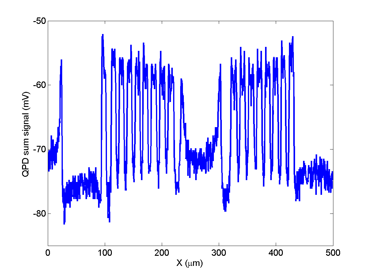
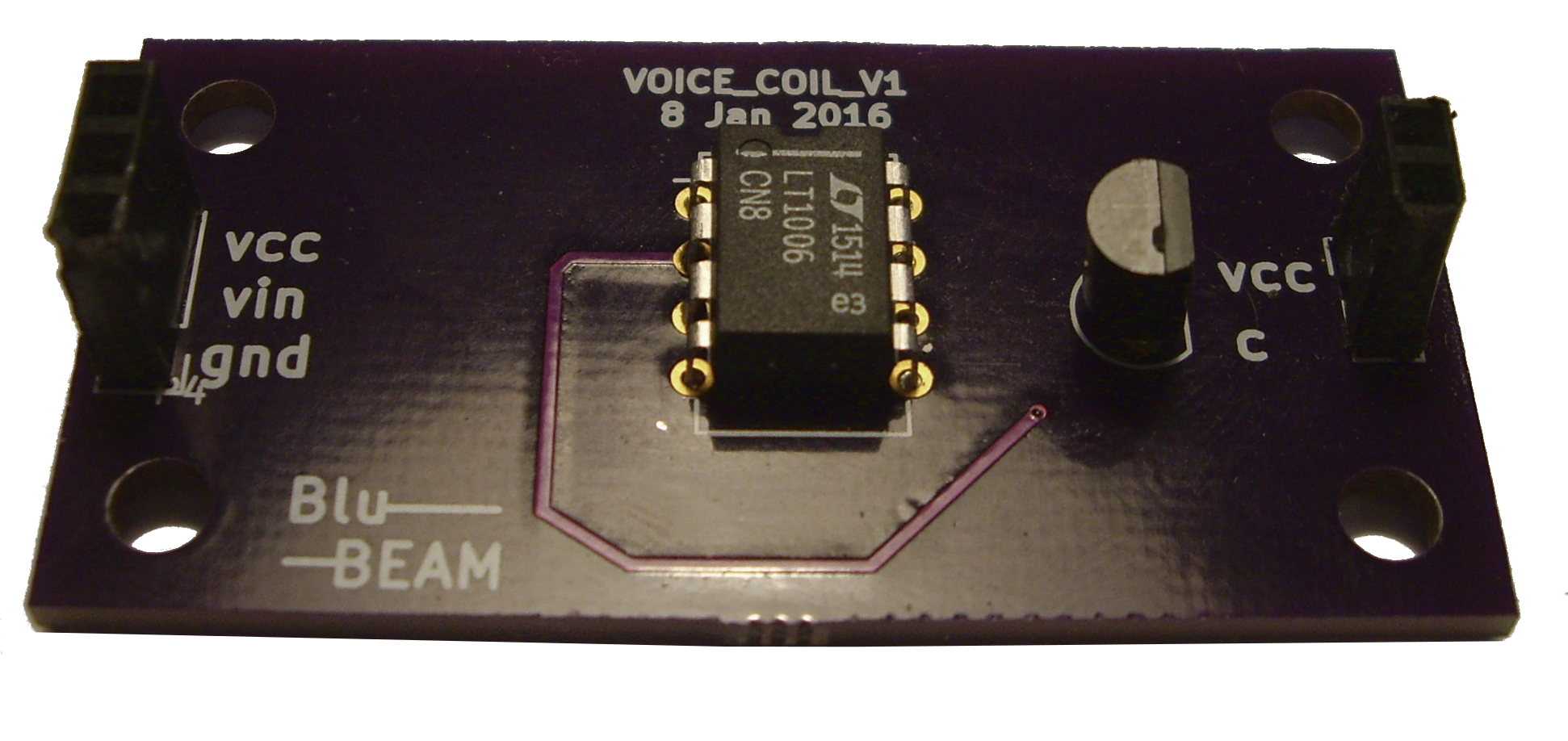
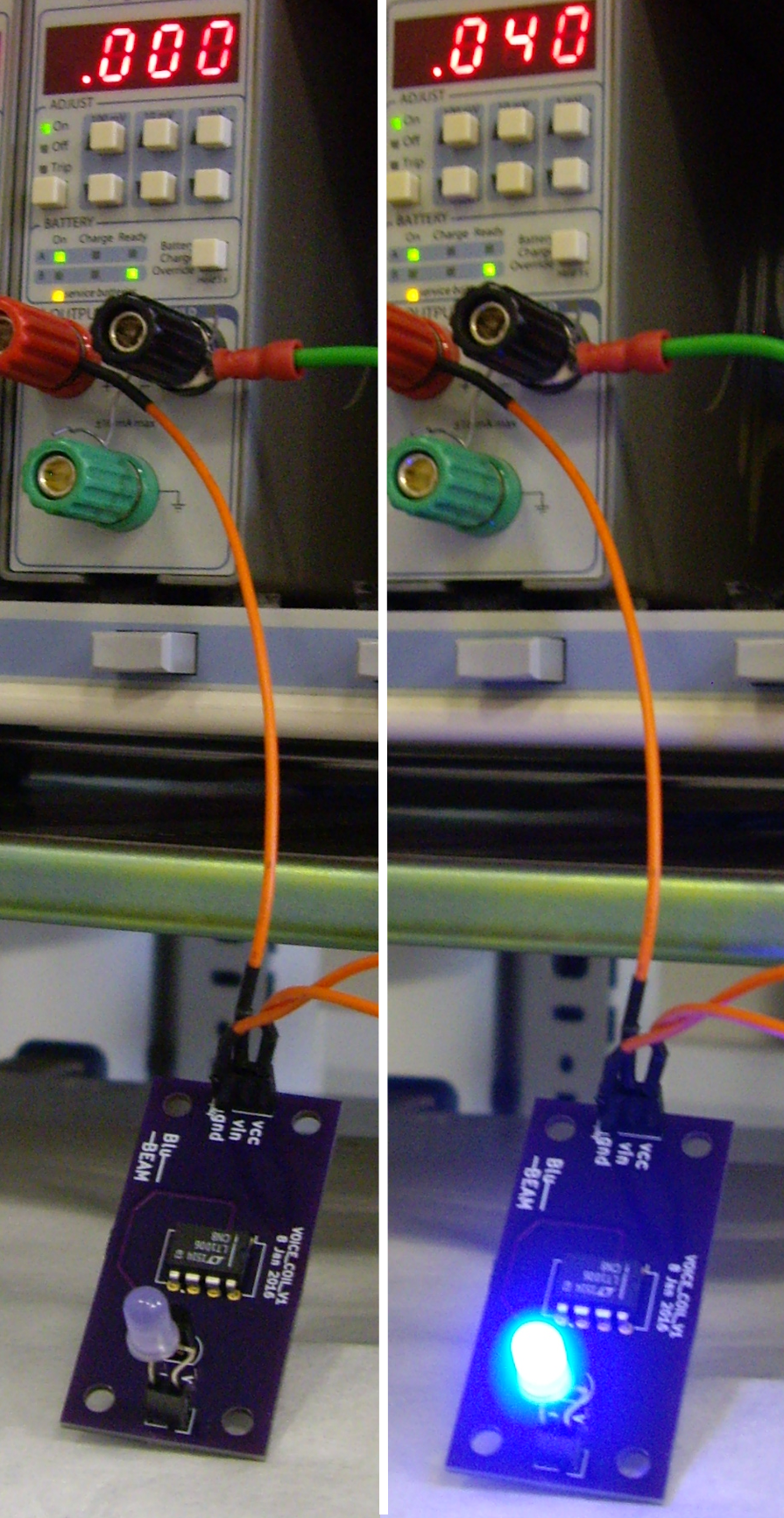
    It allows us to have a dynamic focus range of several mm, paired with μm precision, all controlled by an DC voltage input to the VC driver board. The lens in the assembly is also pretty good, with a numerical aperture NA = 0.85. NA is important especially in microscopy, as it sets the resolving power: the smallest detail that can be resolved by the lens, and thus the microscope, is proportional to λ/2NA, where λ is the wavelength. So, in theory we should be able to separate details that are as little as 240nm apart. In theory...

    We also have a high precision x-y-stage in the setup now. It can displace the sample under the objective at sub- μm precision.
    From tests Andrew did in his amazing Michelson interferometer project, we know the amount of z-displacement per unit current (linear with VC voltage) and can now calibrate the focal depth of our setup: about 1 μm. We get this information by repeatedly scanning across a steep edge and stepping the focus (i.e. the VC voltage) for each line.

    We could of course also use that procedure to focus on the sample, but the astigmatic approach makes it so much faster: All we need is to acquire the quad PD signal as function of VC displacement, as shown below.

  • Read-head mock-up

    andreas.betz02/29/2016 at 11:05 0 comments

    It's been a while now since my last log and here's why: We have been busy building a mock-up of the read-head from larger, conventional optical components.
    The PS3 read-head is great as it got everything we need neatly packed into a small form factor. However, because it's such a well engineered piece of tech, the margins for things like head - sample misalignment are small, very small. In fact that was our biggest challenge with it so far, to get the returning beam to hit the built-in quad-photodiode. A quick and dirty comparison of the quad-diode with diffraction grating showed that it's only a few tens of micrometers in size. Which means that a misalignment of less than a degree already brings us way off the little sensor.

    We still wanted to check that we can focus using the cylindrical lens approach, so we built this mock-up:

    It works in exactly the same way, bringing a collimated blue laser beam through the voice coil + lens assembly from the PS3-head, diverting the returning beam with a beam splitter, and finally acquiring the signal with a quad photodiode.

    The voice coil is controlled by our custom made driver PCB, with the set-point voltage coming from a PC DAQ card. We use the same DAQ for the quad-diode later.

    We also have another focusing and a cylindrical lens between the beam splitter and detector, to give us the elliptical-circular-elliptical shape for focusing.

    The quad-diode itself is pretty big and the last focusing lens is mounted on a translation state, which together allows us to compensate for misalignment in the setup.

    So let's see whether we can now compensate for misalignment and get the elliptical-circular-elliptical data we're looking for.
    Here's what we do to get there:

    The quad-diode is oriented in such a way that the two elliptical out of focus beams will cover two opposite quadrants each. So first of all we adjust the system in such a way that all signals from all four quadrants (A,B,C,D) are equal when we move the voice coil through the focal point.

    You can already kind of guess where that focal point is from the above, but the easiest way of finding the "circle of least confusion" (where the cylindrical lens doesn't distort the beam in any direction) is to compute the so called "S-curve" by calculating (A+C) - (B+D), where A & C, and B & D are opposite quadrants. The circle of least confusion is then at 0, because that's where all quadrants are hit by exactly the same intensity.

    So what we see here (from left to right) is first very little signal because we're way out of focus, then more and more light from one elliptical orientiation. The middle part is what gives this the name S-curve, when we go from one ellipsoid through the circle of least confusion to the other elliptical beam. The photodiode is also picking up a good amount of stray light, which means that the circle isn't at 0 here, but at some offset.

    All in all I'm very happy with these results. We're not using the read-head itself, but with the mock-up we are able to get the auto-focus principle to work and we circumvent the alignment problem by introducing an additional translation element.


  • power line filter

    andreas.betz02/11/2016 at 18:02 0 comments

    The last board I made is a filter for the power supply feeding the previous boards. As with any electrical project it's vital that we have a clean power supply, and in particular we want to avoid burning our lasers.

    I'm using mostly big through hole components here, following this schematic:

    And here is the finished board:

    The big question of course now is whether it actually filters and how much. I don't have access to a network analyzer that goes to very low frequencies, so here's what we're going to do instead:
    Make a function generator send a 1V peak-to-peak sine wave with a 1V offset (so we don't annoy the electrolytic capacitors too much) into port P1. Then look at the output at P2 with a scope reading off Vpp at the frequency we set on the function generator.

    OK, so our filter blocks pretty much everything above a few tens of Hz with the -3dB point at around 10Hz! Promising!

  • Laser driver - PCB & test

    andreas.betz02/10/2016 at 17:23 1 comment

    OK, now that we have control over the voice coil and hence the focus, we need also to be able to control the laser and its power.

    We are going to achieve this pretty much in the same way as we did with the voice coil. After all the core principle is the same: supply a defined current (now to the laser diode), and to make things easier get it linearized.

    However, there are also a few small differences we need/want to account for. First of all, we won't need quite as much current this time. The lasers work at around 20 - 40 mA, compared to the 100+ mA of the voice coil. More important still is the fact that the laser diodes are quite fragile. So in addition to the general current driver circuit we need to include a protection circuit that shorts out the laser if there's too much current or a reverse current. This can be easily achieved with a Zener diode plus a normal diode in parallel with the laser.

    The rest of the circuit is as I said, pretty much the same as the voice coil one, except for the values of components. We are e.g. using a faster op-amp (LT1215) and higher capacitances for the set-point filtering.

    There is another part of the circuit that is obviously different: the opto-coupler part. I am not going to implement it just yet, but it's purpose is simply to allow us to quickly switch the laser off if needs be by grounding the non-inverting pin of the op-amp.

    And this is what the end result looks like.

    The PCB also includes a port to measure the voltage across the 33Ohm resistor (between the BJT and ground), which gives us this plot of current vs setpoint voltage V_set:

    Again, all nice and linear and we can easily reach the 20 - 40 mA we need for the lasers. We could even change the 33Ohm for say 100Ohm if we wanted to increase precision.

  • Voice coil driver -- PCB & test

    andreas.betz02/04/2016 at 11:54 1 comment

    OK, now that we have our PCBs from OSH Park we can get on with populating it and finally checking that we get the linearized current we need for the voice coil.

    So first off, here is the schematic again.

    For the resistors and capacitors we chose surface mount components (size 0805 for easy hand soldering); the op-amp and bipolar transistor are through hole. Note also that instead of a 1kOhm resistor I'm now using 20 Ohms to allow for sufficient current. Depending on how precisely we need to drive the voice coil and what resolution we can get from the set point voltage source (most likely 0-5V), we may have to rethink that value.

    Since the voice coil driver doesn't need to be particularly fast, but should run off a single 5V supply, we're using a Linear Technology LT1006 here. The transistor is a Fairchild PN2222A.

    Here's the finished board. All SMD components are on the back, by the way.

    As you can see from the schematic, Vcc will be a 5V supply and Vin sets the laser current.

    So let's give that a go then:

    First of all, I'm going to test the board and circuit by putting in an LED instead of the voice coil (so much easier to see... :), supplying 5V Vcc and a set voltage on Vin.

    Works nicely. Vin values below 40mV obviously light the LED less brightly.

    Next, I need to check

    a) what current we get as a function of voltage on the BJT base (Vin),

    and

    b) whether that current is linear now. That's the whole point of having an op-amp in the board...

    So let's switch the LED for a resistor and measure the voltage Vr across it vs BJT base voltage Vin. Vcc is 5V as it also supplies the opamp. Ohm's law then gives us the current through the resistor Ir = Vr/R.

    I've tested the current output with two different resistors, a 1k and a 9.7 Ohm. The latter is a much closer match to the actual resistance of a voice coil. As you can see from the graph above we've achieved what we needed: the output is linear with set point Vin, and our range is OK too, as Vin = +/- 2V will result in about +/- 100mA.

  • PCBs!

    andreas.betz02/04/2016 at 11:15 0 comments

    Hooray, our PCBs have arrived!

    All in OSH purple and gold plated contacts.

    Now it's just a matter of getting components soldered on and we can test them.

View all 15 project logs

Enjoy this project?

Share

Discussions

Edwin Hwu wrote 08/23/2018 at 20:20 point

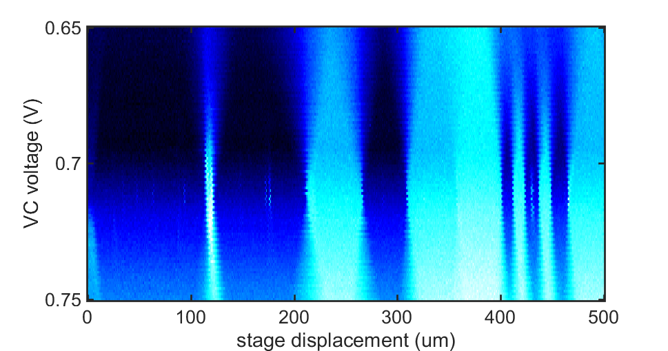
Cool! maybe you can also check my hacking: https://www.youtube.com/watch?v=5bqujaldaCQ

  Are you sure? yes | no

Dylan wrote 10/21/2016 at 08:45 point

The sample reflectivity will influence the laser intensity that illuminates on QPD. This will influence the feedback error signal and therefore the feedback control. How do you solve this problem?

  Are you sure? yes | no

Justin Kenny wrote 07/08/2016 at 04:41 point

What kind of X-Y stage are you using?

  Are you sure? yes | no

andreas.betz wrote 07/26/2016 at 15:11 point

Hi Justin, we're using a stage from Aerotech that is able to move at submicron steps.

  Are you sure? yes | no

Domen wrote 06/27/2016 at 08:33 point

Hi again! 

You have done an awesome job with this project so far, I was happy when I saw you succeeded in takih the first pictures. :)

I'm working on an aeroponics project. The mist should be between 5 and 50 microns for optimal absorbance as NASA found out in their research.

Could this microscope be used to measure the droplet size of the mist?

  Are you sure? yes | no

Andrew Ferguson wrote 06/30/2016 at 09:45 point

Thank you for an interesting question. Not as it stands. It would be interesting to try and do this, and you can be almost sure there is some laser based technique to measure droplet size. 

  Are you sure? yes | no

Gus Fantanas wrote 06/21/2016 at 02:56 point

Hi, Andreas—In your figure above, I think there is an error:  Shouldn't  the polarizing beam splitter be rotated 90° clockwise (or mirrored with respect to the vertical axis), if you want to use the quad photodiode to focus on the sample?


Excellent work!

  Are you sure? yes | no

andreas.betz wrote 06/24/2016 at 20:09 point

yep, that's right. Thanks for spotting that Gus!

  Are you sure? yes | no

Diyouware wrote 06/19/2016 at 09:27 point

Hi Andrea. Well done! Please, take a look at our art. We hacked the PHR803-T Pickup, https://hackaday.io/project/4948-hacking-the-phr-803t-blu-ray-pickup which is similar to the laser unit you are using. Main diference is that we are driving the pickup directly using the own pickup electronics. You will find all the schematcs and tutorials on our site. www.diyouware.com

  Are you sure? yes | no

andreas.betz wrote 06/20/2016 at 20:14 point

Brilliant work! Very inspiring and nice write-up. Thanks for the tip!

  Are you sure? yes | no

andreas.betz wrote 06/15/2016 at 21:15 point

Thanks for your encouragement guys! 

As of a few minutes ago BluBEAM is entered in the "citizen scientist" round.

By the way, if anybody has a good idea for stuff to image, please let us know. 

  Are you sure? yes | no

johnowhitaker wrote 06/15/2016 at 19:06 point

This project is truly terrific! Gets me inspired each time I see an update :) Why isn't it entered in the prize? It's perfect for the 'citizen science' round!

  Are you sure? yes | no

PointyOintment wrote 03/20/2016 at 07:28 point

You should enter this in the Hackaday Prize! It would be a great fit for the Citizen Science round, and would probably get lots of skulls in the current seed funding round (where 1 skull = 1 dollar to you).

  Are you sure? yes | no

John Stockton wrote 03/01/2016 at 13:01 point

Very nicely done.  Getting the alignment right on any setup like that is always difficult.  The cylindrical lens to quad sensor alignment seems tough.  Did you rotate the quad sensor till you had the right A,B,C,D imaging that you wanted?  The good news is that someone else did that already in a DVD head assembly!

  Are you sure? yes | no

andreas.betz wrote 03/02/2016 at 10:53 point

Thanks John.
We're using a fairly big quad diode here (nearly 1cm in diameter), so getting the rotation right isn't too difficult. Getting the focal spot to exactly hit the middle between all four quadrants, that was the tricky bit.

Hopefully we'll be able to image with the mock-up soon, before we tackle the read-head again...

  Are you sure? yes | no

John Stockton wrote 02/17/2016 at 13:09 point

Maybe the quad detector being small is a "feature" in the sense that it effectively might act the same as the second pin-hole.  If it is at the focal point of the receive path then the out of focus light might not be captured as well.  If the laser-side pin hole was the same dimension as the quad detector aperture then you might still have a confocal configuration.  Focusing could still be an issue as you would like the cylindrical lens for the focus servo loop.

On the Y-motion, I'd recommend using the stepper motor and lead screw from the drive.  In practice they routinely control the position of the head to a track-width so that resolution should be good enough.  You can always micro-step the stepper for better resolution.  Since you don't have anything to lock onto as you move the head, just driving it open loop should be good enough.

I don't have the paper, but here is an interesting link: http://www.ncbi.nlm.nih.gov/pubmed/23440071

  Are you sure? yes | no

John Stockton wrote 02/16/2016 at 14:45 point

On the topic of using a DVD head as a microscope scanner - I get how you can have two dimensional movement with the head's internal galvo mechanism (say X and Z), but will you move the head on the rails to achieve scanning in the Y dimension?  Also, don't you need to include a pin-hole in the optical path that isn't there already?  I assume the working distance in Z will be about the same dimensions as what the head height is normally for a DVD drive and the focus range will be about 50um (which I recall as the vertical run-out spec for CD ROM media).  I can't wait to see some images!

  Are you sure? yes | no

andreas.betz wrote 02/17/2016 at 11:04 point

That's right, so far we'll only be able to get line scans of about 1mm or so in length using the voice coil. We're still debating whether to move the head or the sample in the 3rd direction. Either way we're probably going to use a stepper+lead screw (like in a CD drive) or maybe we'll buy a micropositioner and drive it with a stepper.

We should be alright without an aperture and it would be much easier too, but then it's not really a confocal microscope anymore... Also focusing will be trickier without aperture or cylindrical lens. The latter is still my favourite but the quad photodiode in the PS3 head is just sooo small. We really need to be aligned with the sample to less than 1 degree to hit it. So there's some engineering problems we have to overcome but I'm still hopeful :)

  Are you sure? yes | no

John Stockton wrote 02/13/2016 at 02:30 point

BTW - on the voice coil driver, look around at the driver circuits for galvos used in laser light shows.  To get better position accuracy at high speeds, they typically use a closed-loop driver which contains a combination of a proportional, integral and a differentiated versions of the error signal (so called PID loop).   It looked like your drive scheme was open-loop  (without any feedback error information) and this will be difficult to get any long term repeatability.  I'd recommend finding some way to get an error signal back.  Maybe a capacitive sensor or optical, but closed loop systems are much more repeatable than open-loop ones.  If you have this nailed already - ignore this comment :-)

  Are you sure? yes | no

andreas.betz wrote 02/15/2016 at 10:04 point

Thanks for the comment John.
And yes, you're right, we need some type of feedback on the voice coil. Though absolute position isn't the critical parameter, but rather whether we're in focus. For that we're just going to copy what's already in CD drives: cylindrical lens + quad photodiode. That way we always know whether we're too far/near or in focus.

  Are you sure? yes | no

John Stockton wrote 02/13/2016 at 02:19 point

Have a look at this Intersil laser driver chip - Mouser P/N: 968-EL6204CWZ-T7A (for $5.65 each qty = 1).  It can handle the drive current, back facet power monitor as well as the RF ripple current modulation (through an on-board oscillator) to keep the laser in multi-mode operation.  Not very difficult to use and infinitely better than an open-loop drive scheme.  Probably worth a PCB spin just to try it out.

  Are you sure? yes | no

andreas.betz wrote 02/15/2016 at 09:58 point

Thanks John!

  Are you sure? yes | no

John Stockton wrote 02/12/2016 at 14:19 point

On the topic of driving lasers - One of my buddies was a CD ROM optical head designer years ago (I've since lost touch with him), but he was telling that they would add a 900 MHz oscillator output along with the laser current source for writing applications.  The purpose was to keep the laser from operating in a single mode (which would create coherent speckle).  This evidently was critical to keep the optical power level uniform for writing.  This may be something to keep in your mind if you see coherent speckle in your images.  The oscillators are available at Mouser, but I don't recall much about them other than that.

  Are you sure? yes | no

andreas.betz wrote 02/12/2016 at 17:16 point

Thanks for the help John!
I'm not sure we'd be able to modulate at such high frequencies though (need to check the op-amp specs), so I hope we won't get any speckle :)

  Are you sure? yes | no

Paul wrote 02/04/2016 at 15:53 point

Are familiar with the work of Micah Scott, @scanlime? Her Coastermelt project included some brilliant firmware RE work on blue ray drives for guerrilla holography. It may be worth looking into.

  Are you sure? yes | no

andreas.betz wrote 02/04/2016 at 16:02 point

No, I hadn't heard of her or her coastermelt project yet. Thanks for the tip, I'll check it out!

  Are you sure? yes | no

Domen wrote 01/23/2016 at 11:02 point

I'm really hyped about your project :D 

Your writing style is very clear, informative and interesting.

I hope you'll stay as motivated for this project as you were at the start. :)

Best of luck (and motivation)!

  Are you sure? yes | no

andreas.betz wrote 01/23/2016 at 19:01 point

Thanks, glad you're enjoying it so far! :)

  Are you sure? yes | no

andreas.betz wrote 01/22/2016 at 12:25 point

Thanks!

  Are you sure? yes | no

DeepSOIC wrote 01/21/2016 at 15:12 point

Hi!

I hope this will help you get up and running: great info on how CD pickup work.

http://www.repairfaq.org/sam/cdfaq.htm

  Are you sure? yes | no

Similar Projects

Does this project spark your interest?

Become a member to follow this project and never miss any updates