0%
0%
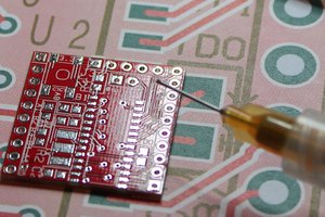
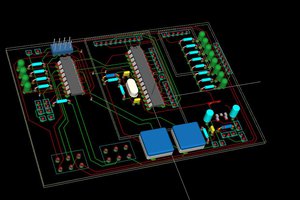
10DOF FeatherWing
a 10DOF board for Adafruits Feather
 turbinenreiter
Become a Hackaday.io member
Already have an account? Log in.
Just one more thing
To make the experience fit your profile, pick a username and tell us what interests you.
Pick an awesome username
hackaday.io/
Your profile's URL: hackaday.io/username. Max 25 alphanumeric characters.
Pick a few interests
Projects that share your interests
People that share your interests

 Michael O'Toole
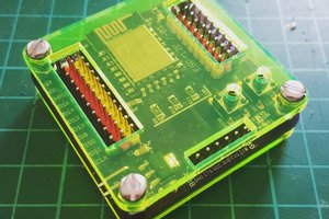
 davedarko
 Ted Russ
Nice board! About the silkscreen, maybe those missing labels aren't in the t/bNames layer? t/bValues mostly get ignored.
On another note: you might want to remove the epf file from your github, since it stores informations about your system and isn't really needed for sharing. Just put it in your .ignore file and may be look into this http://stackoverflow.com/questions/3458685/how-can-i-completely-remove-a-file-from-a-git-repository