 Tobias
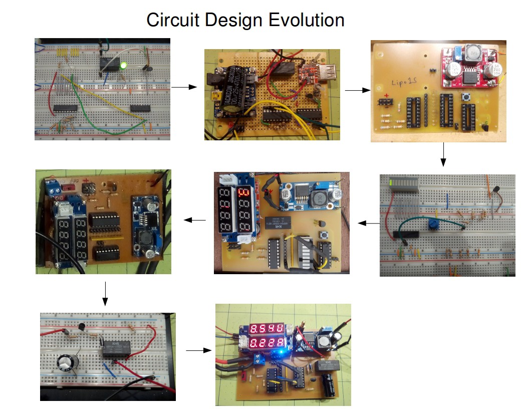
I started out with the goal of powering a single computer board with a solar panel and a battery backup.
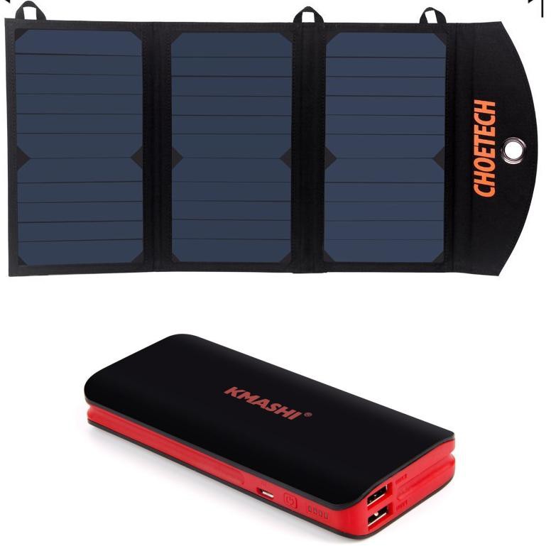
The simplest solution appeared to be: A USB charging solar panel with USB power bank
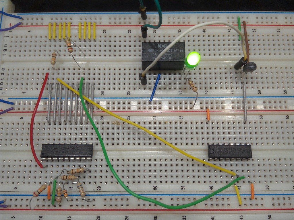
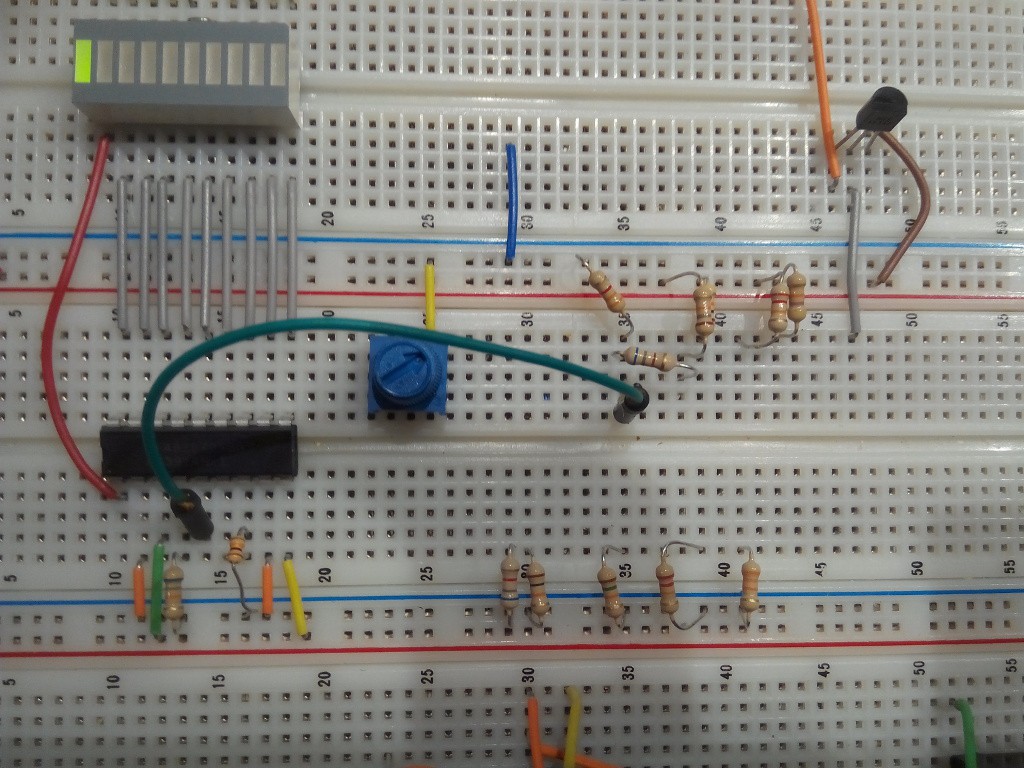
This did not work because some USB power banks do not output power when a charging cable is plugged in. In addition, I noticed that the Banana Pro will stop running when the battery voltage drops too low, but it will not reboot when solar charging increases the voltage because the voltage never went to zero. There is a region of voltage in which the microcontroller could be stuck for a long time, without actually running. So I came up with the idea of a circuit that has multiple comparators and a latch for hysteresis so that a controlled computer shutdown/ reboot can be accomplished. Here is the first breadboard implementation:
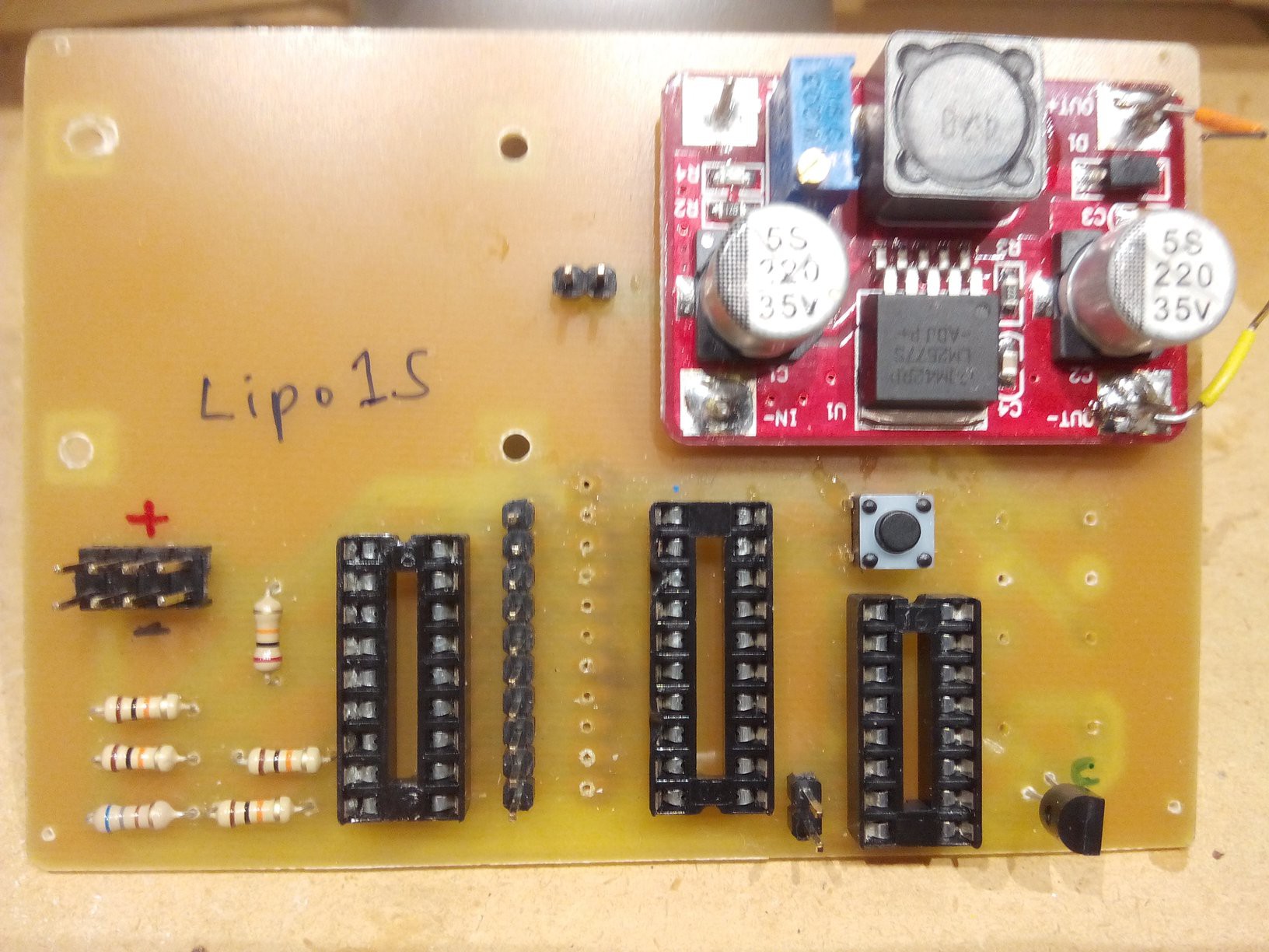
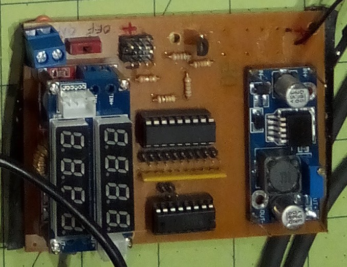
and the first protoboard implementation:
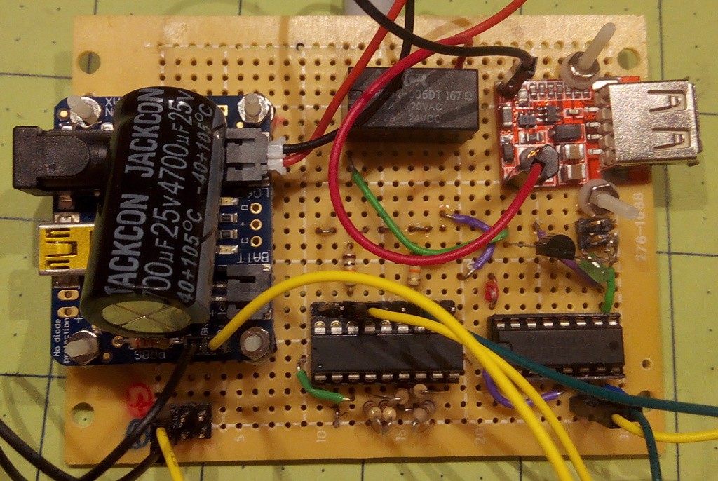
On the left is a Adafruit solar charger controller and on the right is a step-up boost converter to convert the 3.7 Volt of the Lipo battery to 5 Volt. The shutdown and the bootup voltage can be selected by choosing any of the pins on the pin header next to the LM3914.
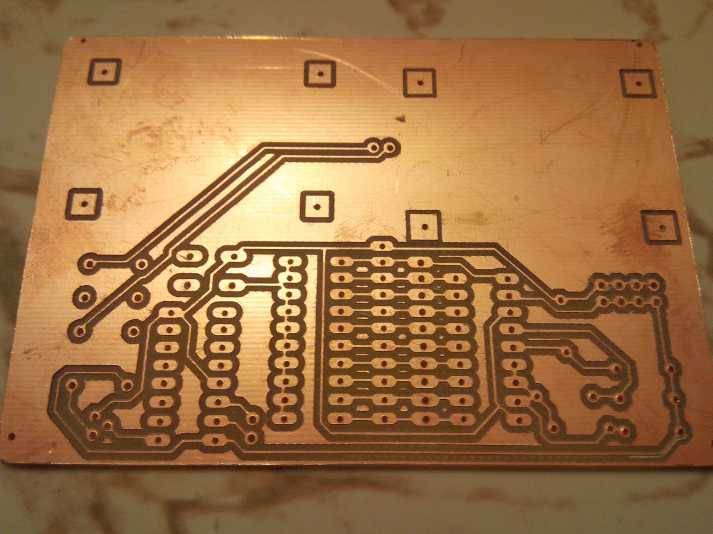
Since I was now making PCB's regularly, I also put together my Zen Toolworks CNC for PCB milling.
This worked for a while, but eventually the boost converter burnt out, and I noticed that during boot, over 1 Amp can be pulled from the board! At the time, I was also looking for a rover platform, and the one that I chose has motors that need at least 6 Volts to run. So I decided to switch to Lipo 2S batteries which can provide between 7.4 and 8.4 Volts. This turned out to be a good decision because now, the microcontroller-caused current never goes above 300mA. I am convinced that buck-down conversion is more efficient than boost-up conversion, at the least, lower currents cause fewer problems. I would never voluntarily run a 5 Volt microcontroller from a 3.7 Volt battery again.
The circuit for the LED controller had to be changed so that its turn-on and turn-off point could be set between 7.4 Volts and 8.4 Volts.
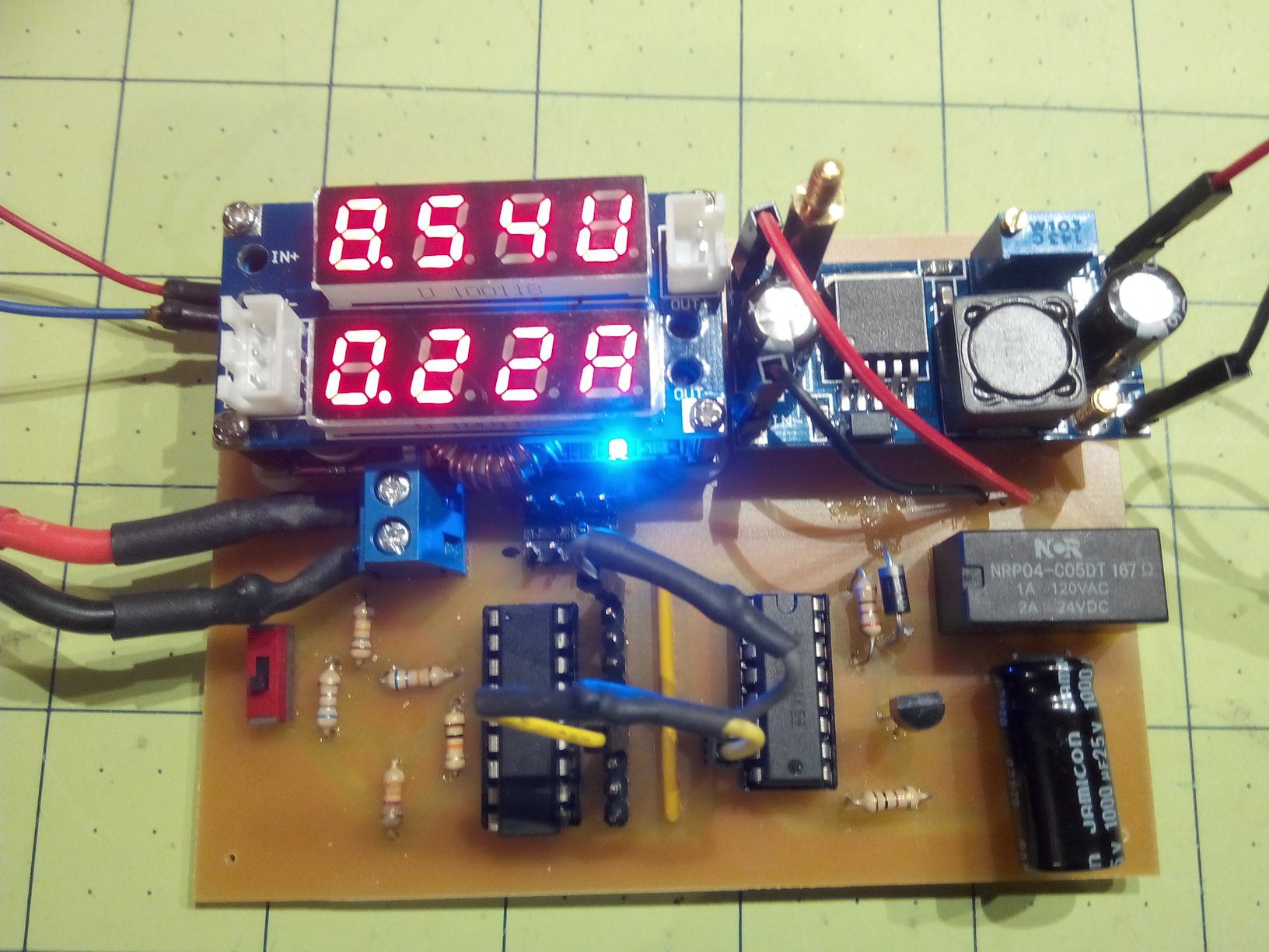
Since I was using a new voltage, I had to get a new charge controller. I looked for lipo2S solar charge controllers and only found two on Ebay, both of which I ordered and both of which do not work (at all). So I used a step-down converter from a 12 Volt solar panel to 8.4 Volt with current limitation. The one that I currently use has a voltage and current display which is very useful.
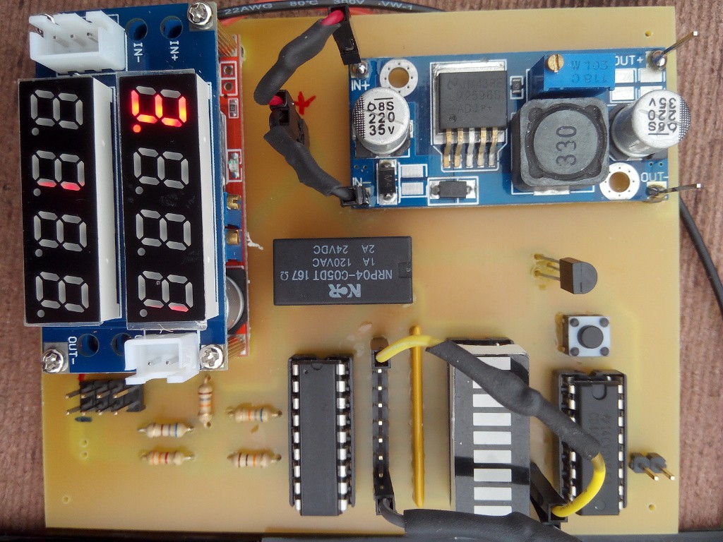
On the left is the buck converter for the solar panel and on the right is the buck converter to the microcontroller.
I also added a 10-LED bar display to show the battery voltage, but removed it in the next revision because it interferes with the outputs to the latch.
One problem I had with this circuit is that when I connected a solar panel under low lighting conditions, the relay would turn on and off at a high frequency (rattling sound) and eventually, the circuit stopped working, probably because the transistor or the relay burned out.
I decided to try a time delay circuit, based on a capacitor, and also finally added a flyback diode
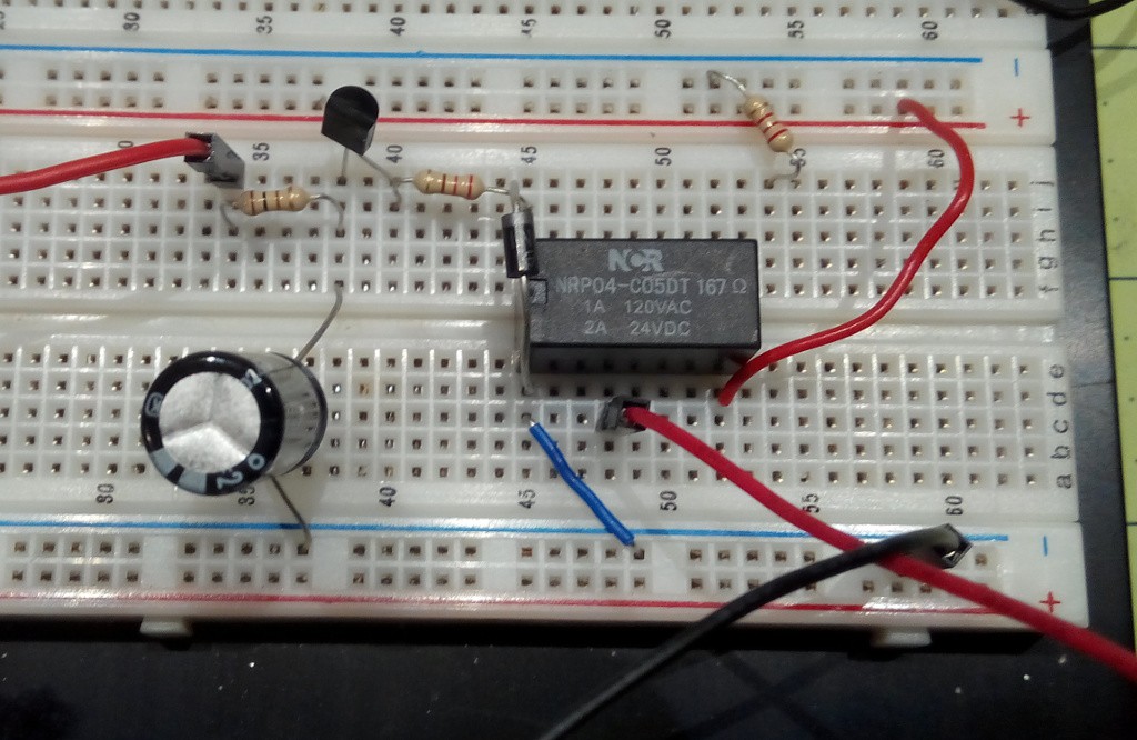
In addition, I put a 200 Ohm resistor between the voltage source and the relay and the current dropped from 40 mA to some single digit number that is not even showing on my power supply's decimals. You can literally hear the difference in the relay sound when you increase the resistance. One of the reasons I like the relay over a solid state relay or a MOSFET is the audible feedback, and when the relay is off, it is really off.
I took the board out in the sun today and exposed it to low light conditions where it turned on and off periodically, but this time, the frequency was less than once per second which is not going to destroy the relay. This condition only occurs under low light and when no battery is connected, which is only during maintenance, but now, that can't destroy my board either.
ref: Designing a Li-Ion Battery Gauge with the LM3914 - EEVblog #204
Discussions
Become a Hackaday.io Member
Create an account to leave a comment. Already have an account? Log In.