 Yann Guidon / YGDES
The new oscillator works well but it is quite sensitive to the power supply's voltage. A change of 0.1V requires the trimmers to be re-tuned.
A very good voltage regulator is necessary to preserve the frequency accuracy. This is the only exception to the "no IC" rule I've set myself.
Initially I have chosen 2.5V because there is 0.5V of margin from the 3V input supply and it's easy to obtain with the LM4041-ADJ shunt regulator (a pair of resistors of identical values increase the 1.25V output to 2.5V). The goal is to have a stable, temperature-independent voltage for the oscillator to reduce long-term drift. But it's not so easy in practice.
The LM4041 needs 60µA and draws more from the shunt operation. This is getting ridiculous because the oscillator draws less than 40µA. Overall, the power consumption is more than doubled!
One solution is to use a voltage regulator in SOT23, for example, though these chips are designed to handle more current, while absolute voltage accuracy is a second thought. I should instead use a micropower 2.5V voltage reference !
Digging in my old collection of samples (they were gathered to experiment with voltmeter accuracy) I find the following parts:
- REF3125 (Thank you TI!)
- REF3225 (Thank you TI!)
- MCP1525 (Thank you Microchip!)
- MAX6002 (Thank you Maxim !)
Speaking of current, the 3 first references are rated around 100µA, which is more than the LM4041 alone, but without the hassles of calculating the series resistor of the LM4041, which risks drawing even more current when badly chosen, so this is equivalent. There is no risk of losing regulation, if the input voltage drops dangerously low, and the current draw is almost constant.
The MAX6002 has a 100ppm/°C tempco, which is too much, despite the lowest current needs (45µA). I only have 2 samples so I can't go far and it's ruled out. Same for the bigger brother MAX6102 (only 1 sample left) with a bit more stability but more current as well (90-120µA)
The MCP1525 draws about 100µA (90µA typ. according to the datasheet, around 80µA@3V@25°C). The tempco is better (27ppm typ. at full temperature range) and I got 5 samples, I can go further than with Maxim.
The REF3125 has more samples left (7) and has better drift performance (15 ppm/°C max, 5ppm typ at ambient temperature). Noise characteristics are important too : 48 μV RMS from f = 10 Hz to 10 kHz but we'll talk about it later. Quiescent current is announced around 100µA (typ.@25°C). Sounds good.
Now the more recent REF3225 has 10 samples left, maybe because in the past I might have been afraid of the SOT23-6 package. It's still drawing around 100µA but the drift is typically 4ppm/°C. This is stable ! It seems that this is the winner.
If you have better suggestions, please contact me and/or send me samples!
Noise is another thing. Voltage references are noisy. I learned it the hard way, for an audio project, but here, I'm not doing a VHF, ultra-low-jitter oscillator. As long as the frequency is stable over the long term, I'm fine.
So, filter or no filter ? The power supply/input must be filtered with a LC cell to prevent switching noise from disturbing the clock. The output however is something else. I am tempted to over-filter it but this might not be the most efficient approach. The noise might actually help the oscillator to startup faster and the reference might react to the changes in load, which could actually help.
Looking at Fig.17 and Fig.18 of the REF3225's datasheet, I'm tempted to add a small capacitive load to make a long enough "bump" that helps with the startup.
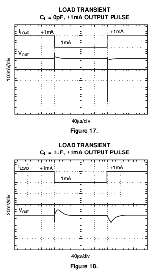
On the contrary, without capacitor, the change in load will make a very short spike that will not bring some rebound to the quartz.
I'm thinking about this because the goal is to startup faster, if needed with the help of an external device or button. I still have to experiment with a shorting MOSFET.
It must be noted that these parts work with light or even no load. It shouldn't be a problem to draw only 37µA, unlike other larger regulators.
Discussions
Become a Hackaday.io Member
Create an account to leave a comment. Already have an account? Log In.