 Alan Chambers
Initial Plan
This is a project I have undertaken since joining the UoM Robotics Society. It is presented in blog form as it happens. For this reason it may contain errors. I intend to leave these in, along with the solutions when I find them so that others may learn from my mistakes. Once the project is finished I will rewrite it so it reads better; for the meantime expect some rambling.
I figured that supplementing a mechanical engineering degree with some practical electronics will improve my skill set and make me more employable. I also thought that, being a student, I would be spending a lot of time procrastinating on doing actual uni work (apparently that's what you do) so if I have something productive to do while I'm procrastinating it's not a waste of time.
Previous experience with robotics and electronics is non existent. 2 weeks before introducing myself at the freshers fair I had not heard of raspberry pi, arduino, python etc; it is safe to say I have started from scratch.
The brief was to create a robot that would operate within a predefined course; it's a sandbox challenge so I could decide on my own goals.
The course:
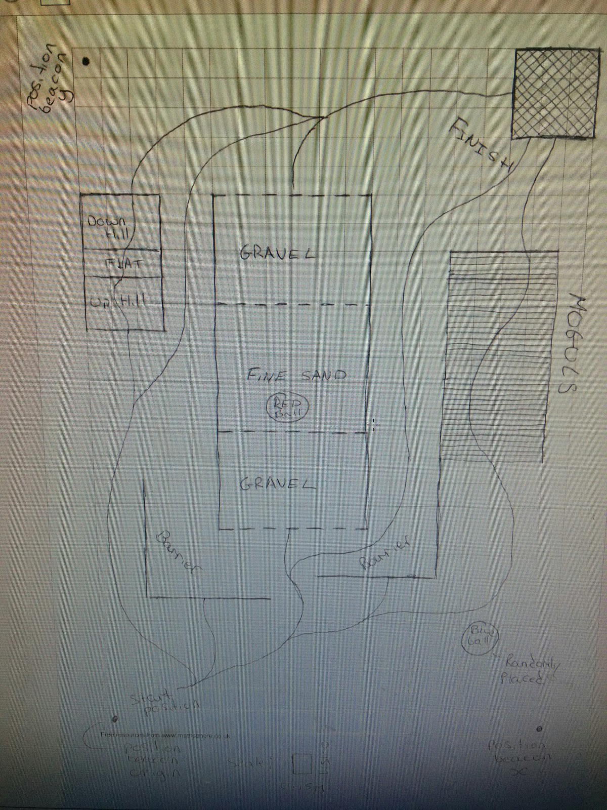
I decided to make a wheeled or tracked vehicle that would follow a line and not crash into a wall (one of the lines goes into a wall).
I wanted to keep the robot fairly simple and my personal goals are:
1: learn how to connect the various components (power supply, motors, drivers, sensors, controllers etc
2: learn some programming
Depending on how this goes I will make the decision to increase the complexity later on. A couple of ideas are to make a tilt and pan mount for the ultrasonic sensor and to install the radio beacon things which may help to determine whether or not the robot knows it is at the finish. If I could also then make it do something to signal it thinks it is at the finish that would be cool.
Component selection
I had a look at raspberry pis and thought that this would be a good start as I was already doing some stuff on code academy in python. I also liked the scratch language that can be used for exploring the concept of programming without getting bogged down in the detail of the code.
I set up a pinterest board and started getting a shopping list together. The pinterest board can be seen as a bibliography, everything on their has had a direct influence on my thinking and the projects progress:
https://uk.pinterest.com/Ageorgechambers/robotics-project/
I quite like this as it enables me to have a visual reference for relevant stuff rather than trawling through a list of bookmarks.
Basic shopping list was: battery and method of distribution, pi 2, motor driver, motors x 2, ultrasonic and line sensors. I didn't know what else I needed at this point.
Ben at the robotics society helped me out, I was given a Pololu dagu rover 5 tracked chassis with built in motors and encoders, a motor driver, raspberry pi 2, some radio receivers, an sd card for the pi, a couple of servo's for a tilt and pan mount and an arduino.
I liked the look of the arduino as it was smaller than the pi and it seemed to be more intuitive to connect due to the pins being labelled.
I then went on ryanteck and picked up some connecting wires, a line follower, resistors, tiny snips and tweezers as the tools I use for my bike were way to big to be used effectively.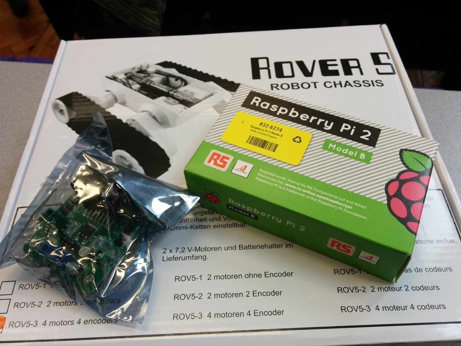
First go at connecting everything up
I decided to get the arduino set up on the Saturday. This was 5 hours of pain.
Getting IDE installed was fine; I could not get the drivers installed no matter what I did.
Whether it was a hardware wizard or manually installing drivers I had downloaded I could not get it done.
In my device manager it did not say 'ports com' as it should, instead just saying 'other device' which I could not get to work. I found myself typing stuff I didn't understand into google and then getting frustrated that I didn't understand the suggestions.
I gave up and decided to have a look at the pi. This is the point I found out that most old pc monitors do not have an hdmi connection so I couldn't play with this either.
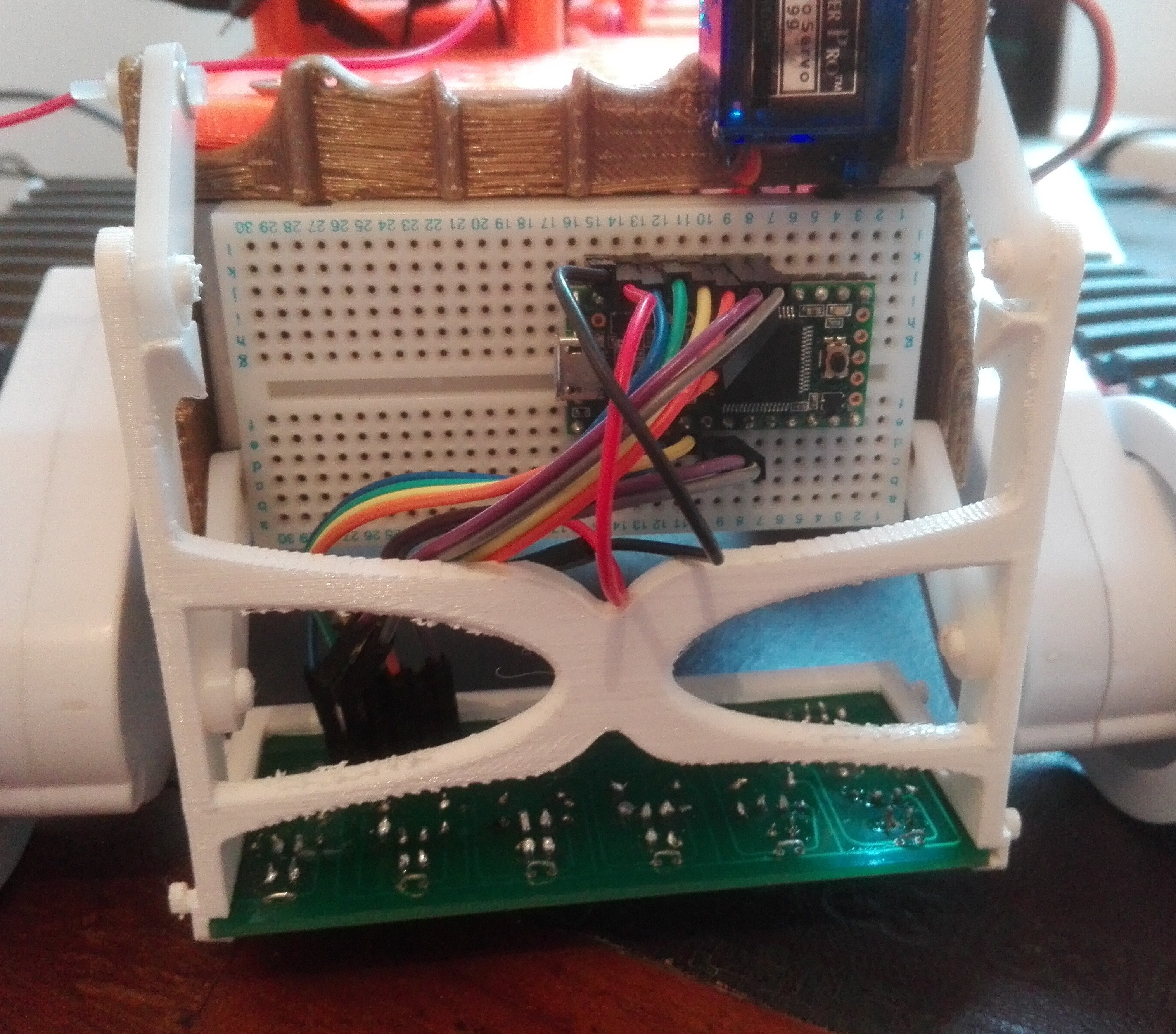
Saturday and sunday night I decided to get the components wired together. I thought it would be best to just use the gpio pins on the pi and leave power distribution separate from the board so I didn't blow anything up. I could then lay out the power circuit on a breadboard and install resistors as necessary.
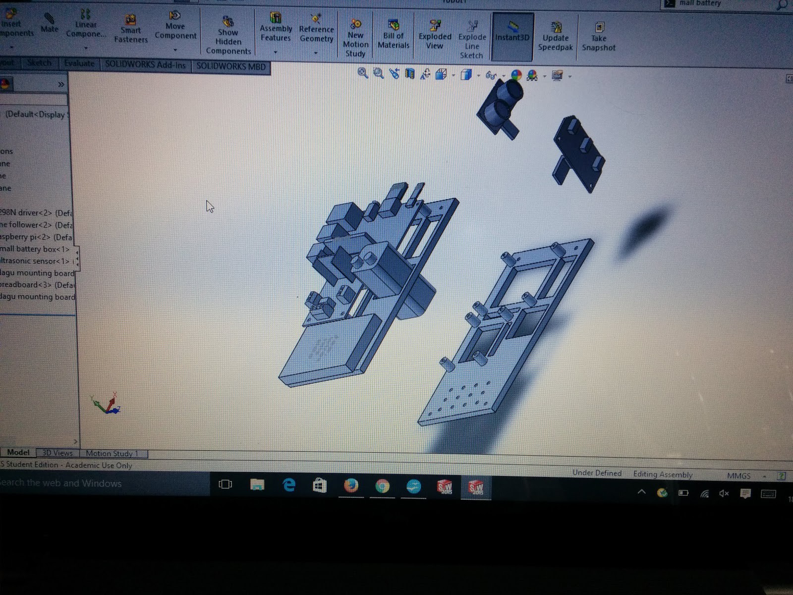
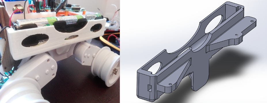
I got the control bits done by the end of the weekend. It looked like this: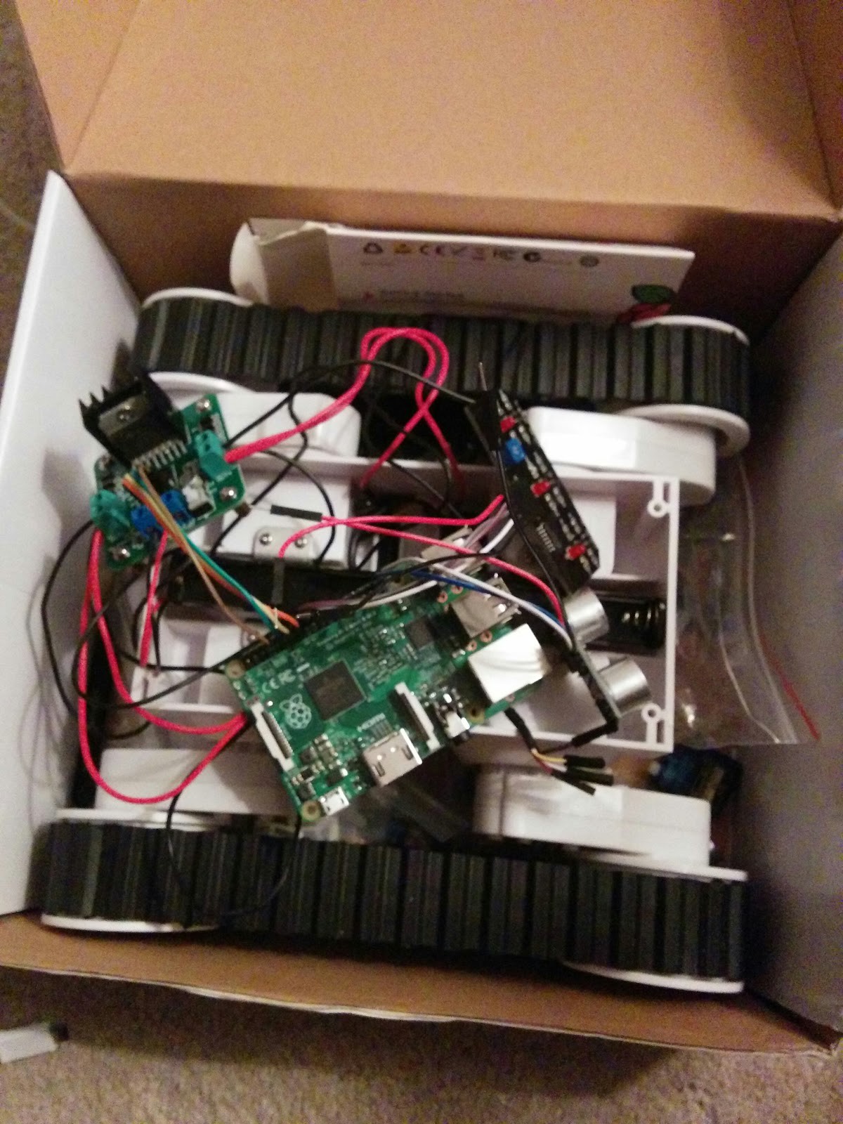 I think at this point I realised that one of my project goals should be to design and build something to hold all this in a way that makes it easy to work and looks nice. I decided to get it done on solidworks and 3d print it. I had used solidworks for the first time the previous week so it was a good bit of practice.
On Monday I went to see Tom in the robocave for some help with the arduino. We got mine working on a different laptop and none of the working nanos would get recognised by my laptop. Turns out that if you have an arduino nano with an unlicensed driver chip then there is a high chance it will stop your laptop from working with any arduino nano.
Once again I got hooked up; Tom sorted me out with a teensy which is much better than an arduino nano and can be made to work with the IDE software by installing something called teensyduino. Unsurprisingly, it's tiny.
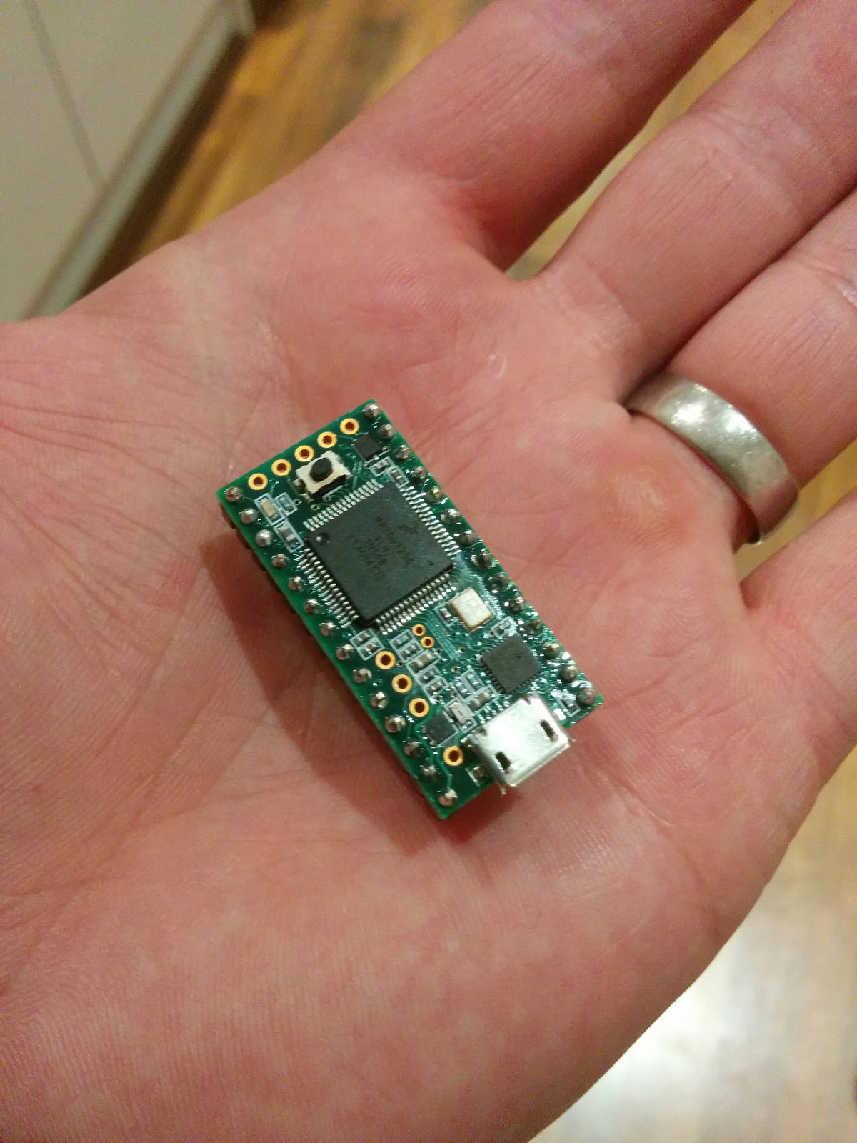 The teensy has the ability to convert analogue signals to digital, something I later found would be quite handy.
Designing a mounting board
I modelled all the boards etc on solidworks so I could play around with the layout of the components.
I designed a board to mount on top of the dagu tracked base which would enable me to mount everything neatly and route the wires.
I had aimed to make separate mounts for the line sensor, ultrasonic sensor etc so I put a pattern of holes at one end of the board to allow things to be switched out. This is also a good size for a small adhesive breadboard.
It fits a 4 x AA battery pack or one of ryanteks Pi power packs (check components for link).
If I were to make another one I would move the motor driver towards an end so that the motor battery wires can be connected more easily.
it looked like this:
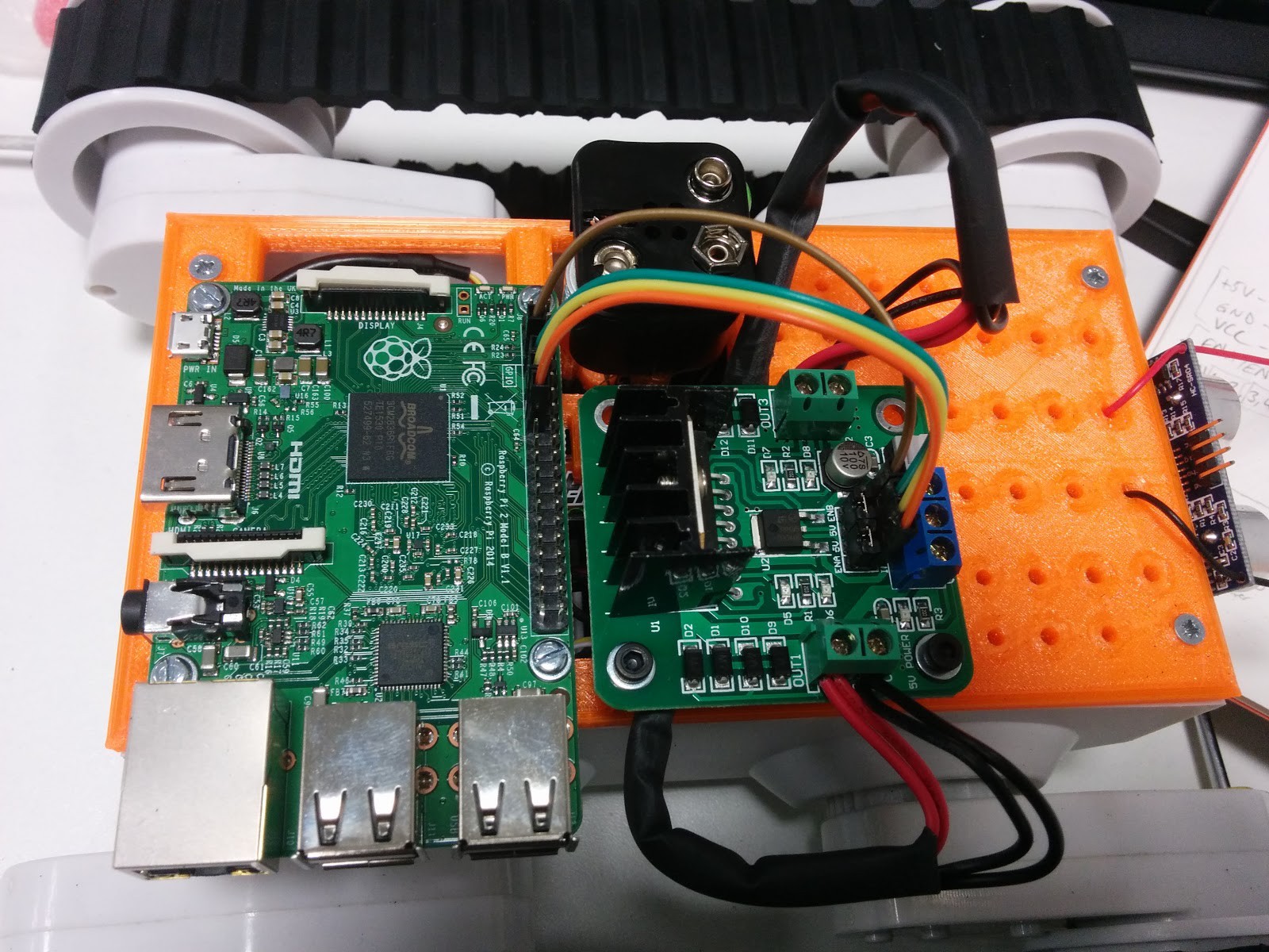
I got my mounting board printed in hot orange and the measurements were fine however I had trouble mounting the motor driver board due to the bolts I was using being to long and hitting the chassis battery pack. Still, 2 of the bolts were fine so I just used 2. If the mounting plate was jacked up using spacers or shorter bolts were used then this would not be an issue either. There is an STL file available in this projects files if anyone wants one.
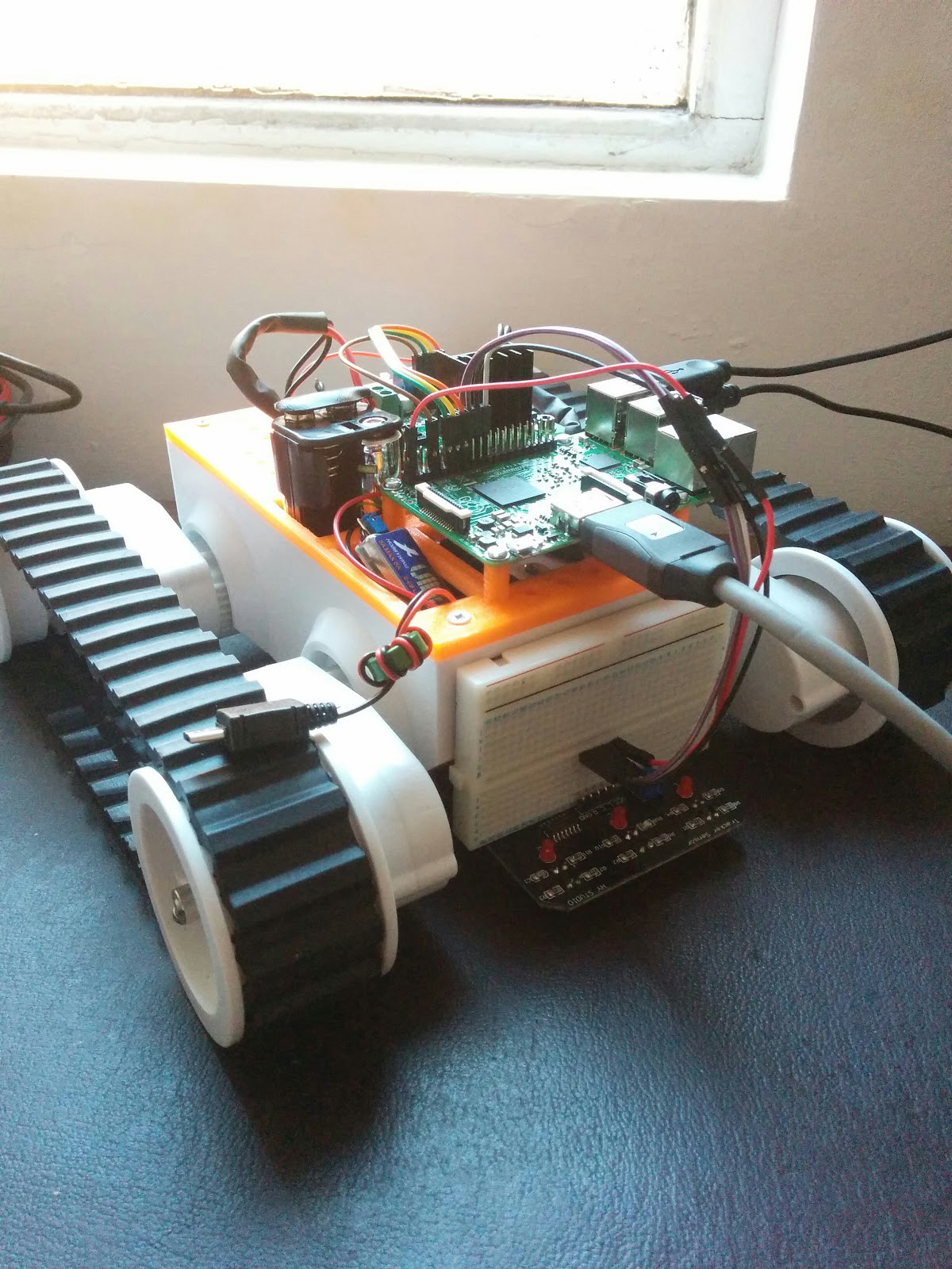
I spent some time on Friday evening wiring it up, on Saturday morning the ubec cable I had ordered was delivered so this got attached too, I was now at the stage where I could get it to do stuff:
Line sensor
I had a line sensor but there was no information available about how far off the ground it should be. The dagu chassis I'm using also has adjustable ride height so I thought I would experiment with the height of the sensor and see what sort of effective range it has. After thinking about designing a height adjustable mount for it which I could 3D print I realised that I could have the same thing by sticking a breadboard on the front and using the different connections to play around with the height. I guess it will affect ground clearance but I only want it to move around on a relatively flat surface; I'm not building a new mars rover.
Next step is to see how it moves and play around with the motors. After that I'm going to play around with the line sensor and see what it can and can't do.
Mobile power
I happened to be in the right place at the right time at uni and was given a mobile charger for my phone by Rachel the careers adviser. After checking the specs it seems it delivers just the right amount of juice for a pi, 5V at 1A. I did some double checking and it seemed to be just the right spec to power the Pi for a couple of hours:
 It was a great fit in the chassis too:
 Seeing as I got given this for free I thought I would give my battery box and ubec cable to another member of robosoc who didn't have a way to power their pi on the move.
L298 driver issues
I struggled to get the robot to do anything and after what seemed like an eternity I realised that the L298 driver has an on-off button. I could not find any mention of this on google so for the benefit of anyone googling 'L298N motor driver does not work' the answer is simple and looks like this, the square white thing with S1 next to it:
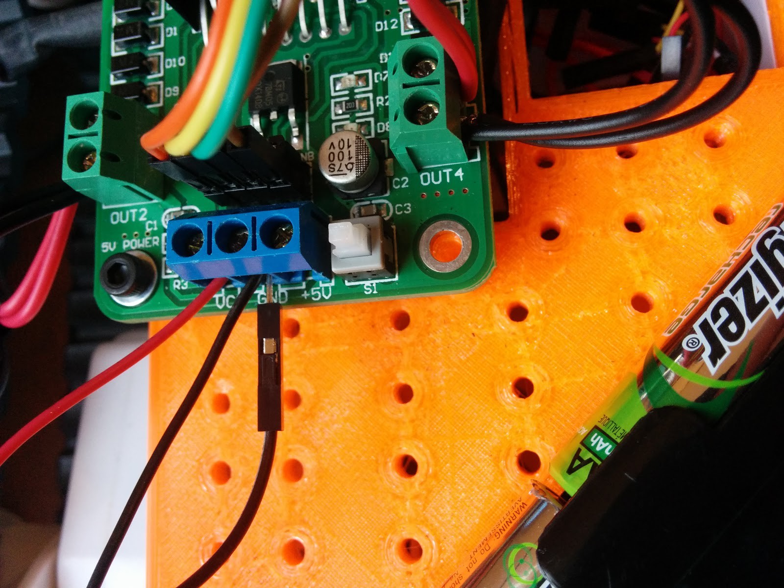
It's also worth noting that the processor needs to have a common ground with the driver, it seems obvious now but it did take a few days for the penny to drop.
Test Code
Next step was to feed it some code to establish the motors did what they were supposed to so I wrote a little test program. I don't think the threading library was necessary but seeing as I was keen to get the thing moving I found some code online and then adapted it for my own purposes. I didn't make a note of the author but its not a straight copy and there can only be so many ways to write a program like this so I'm not too worried about recieving a cease and desist letter any time soon:
import RPi.GPIO as GPIO, sys, threading, time
#use physical pin numbering
GPIO.setmode(GPIO.BOARD)
#pins: 7:motor4, 11:motor3, 13:motor2, 15:motor1.
GPIO.setup(7, GPIO.OUT)
GPIO.setup(11, GPIO.OUT)
GPIO.setup(13, GPIO.OUT)
GPIO.setup(15, GPIO.OUT)
#motor test
GPIO.output(7,GPIO.HIGH)
time.sleep(1)
GPIO.output(7,GPIO.LOW)
time.sleep(1)
GPIO.output(11,GPIO.HIGH)
time.sleep(1)
GPIO.output(11,GPIO.LOW)
time.sleep(1)
GPIO.output(13,GPIO.HIGH)
time.sleep(1)
GPIO.output(13,GPIO.LOW)
time.sleep(1)
GPIO.output(15,GPIO.HIGH)
time.sleep(1)
GPIO.output(15,GPIO.LOW)
time.sleep(1)
GPIO.cleanup()
This code worked fine.
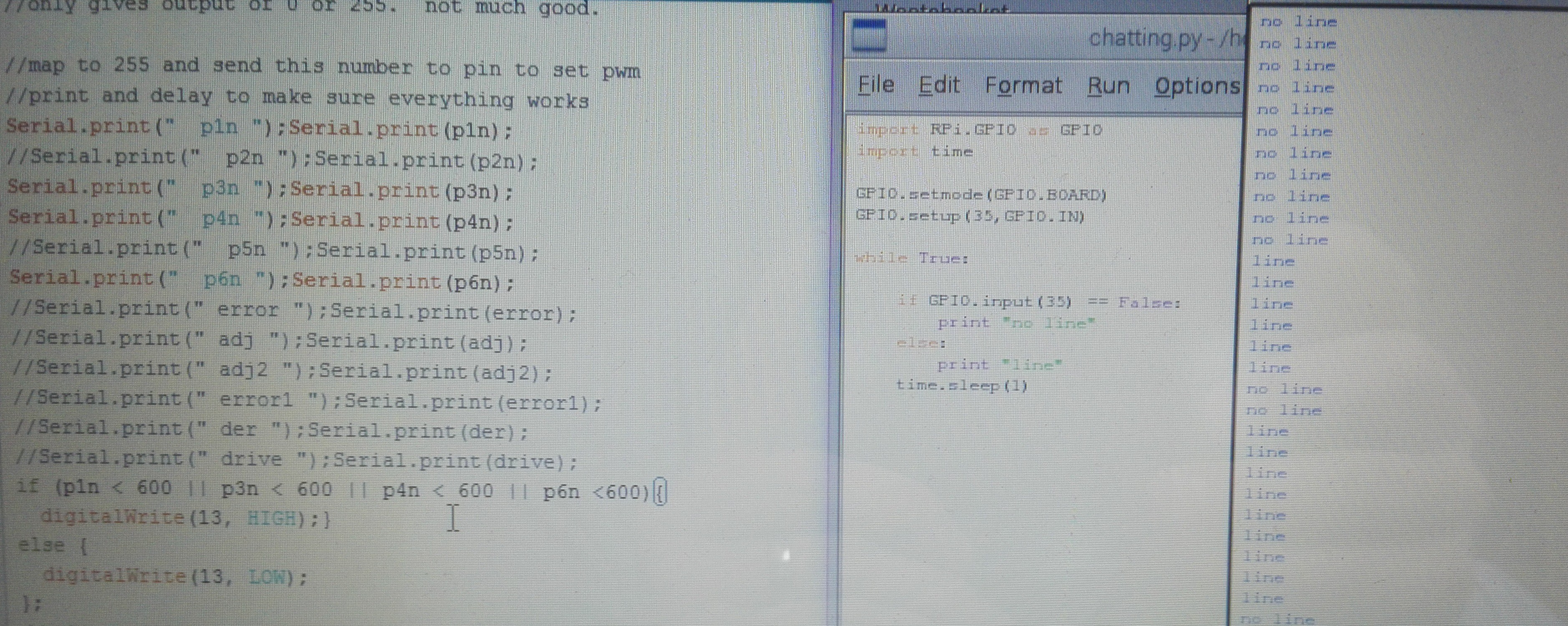
Line following code
This is the code I wrote for the line follower. I decided to have two turning speeds so that it could cope with different radius curves when its trying to work out where to go. I would like it to be as smooth as possible. This worked in a fashion; when I had the robot up on a stand it would pick up a black line on white card and behave perfectly. In practice, once I had taped a course on my kitchen floor, it was erratic. It seemed to prefer chasing the reflection from the ceiling lights rather than follow the line.
import RPi.GPIO as GPIO, sys, time
#use physical pin numbering
GPIO.setmode(GPIO.BOARD)
#pins: 7:left rev, 11:left for, 13:right for, 15:right rev.
GPIO.setup(7, GPIO.OUT)
GPIO.setup(11, GPIO.OUT)
GPIO.setup(13, GPIO.OUT)
GPIO.setup(15, GPIO.OUT)
def Stop():
GPIO.output(7, GPIO.LOW)
GPIO.output(11, GPIO.LOW)
GPIO.output(13, GPIO.LOW)
GPIO.output(15, GPIO.LOW)
def Forward():
GPIO.output(7, GPIO.LOW)
GPIO.output(11, GPIO.HIGH)
GPIO.output(13, GPIO.HIGH)
GPIO.output(15, GPIO.LOW)
def Reverse():
GPIO.output(7, GPIO.HIGH)
GPIO.output(11, GPIO.LOW)
GPIO.output(13, GPIO.LOW)
GPIO.output(15, GPIO.HIGH)
def Left():
GPIO.output(7, GPIO.LOW)
GPIO.output(11, GPIO.LOW)
GPIO.output(13, GPIO.HIGH)
GPIO.output(15, GPIO.LOW)
def Right():
GPIO.output(7, GPIO.LOW)
GPIO.output(11, GPIO.HIGH)
GPIO.output(13, GPIO.LOW)
GPIO.output(15, GPIO.LOW)
def Hardleft():
GPIO.output(7, GPIO.HIGH)
GPIO.output(11, GPIO.LOW)
GPIO.output(13, GPIO.HIGH)
GPIO.output(15, GPIO.LOW)
def Hardright():
GPIO.output(7, GPIO.LOW)
GPIO.output(11, GPIO.HIGH)
GPIO.output(13, GPIO.LOW)
GPIO.output(15, GPIO.HIGH)
#speed is 0.2 m/s
#1 second hardleft or hardright = 45 degrees
#left/right is slight change in direction
#line follower
#IRleft = 16
#IRcentre = 18
#IRright = 22
GPIO.setup(16, GPIO.IN)
GPIO.setup(18, GPIO.IN)
GPIO.setup(22, GPIO.IN)
try:
Stop()
raw_input("Say hello to my little friend.")
while True:
lineleft = GPIO.input(16)
lineright = GPIO.input(22)
linecentre = GPIO.input(18)
#if it picks up a line the input is 0
if linecentre == 0:
if lineleft == 0:
Left()
elif lineright == 0:
Right()
else:
Forward()
else:
if lineleft == 0:
Hardleft()
elif lineright == 0:
Hardright()
else: Stop()
except KeyboardInterrupt:
Stop()
GPIO.cleanup()
Line sensor position
I played around with the IR sensor at different heights, it has a good range and worked ok in the highest position, about 20mm above the ground. The higher it was positioned the more sensitive it was regarding it's position relative to the line. There was also a finer range of adjustment on the sensor itself, which I guess is to be expected.
It was good to play around with the height and the breadboard was ideal for this purpose but using the electrical pins as a mechanical support was not ideal; as soon as the robot turned or hit a bump the sensor wobbled, the robot then tried to adjust itself according to the wobble and not just the line.
I think the maximum usable height for one of these would be about 10mm, I'll use that as the basis for 3D printing a mount for it and see how it goes once its stiffer.
I made a shield out of cardboard for the sensor so that it didn't pick up the reflection of the ceiling lights. This helped a little bit but one sensor in particular was not doing what it should do; I think this may be because I rested a screwdriver across the contacts which made smoke come out.
Second semester plan
The plan for the second semester is to build on what I have already achieved rather than to try something new. I will tweak the code so that it will work with a black or a white line, this could be defined by a user input at the beginning of the code.
I'm also going to see if I can get it working with the teensy because the Pi is frustrating to use if you don't want to carry around a spare monitor, mouse and keyboard. If I can get it working with just one brain then I'll be very happy.
I also intend to design and make a new sensor using eagle which will give an analogue output. This in turn will be used to calculate a value for the pwm for the motors and allow more variety in terms of turning circles. I've been reading about PID controllers and I like the concept, this will be part of the design provided the initial steps go ok.
Once it follows a line perfectly I will connect the ultrasonic sensor so that it doesn't crash into walls; i will also give it something to do when it can't pick up a line. The course has a couple of sections where the line disappears and If it chooses to take one of these paths I don't want it to stop.
I've been advised to create a github account for my code, once I find out what a github is I will have more to say on it.
Semester 2
The main focus at the start of February is to build a sensor array that will give an analogue output. I picked up some photoresistors, leds and IR emitters and had a go at making a circuit. I downloaded he icircuit app which proved to be very useful; if you're like me and have no prior knowledge of circuit design/analysis then it's a great way to get a head start. It also allows you to prototype basic circuits without blowing anything up.
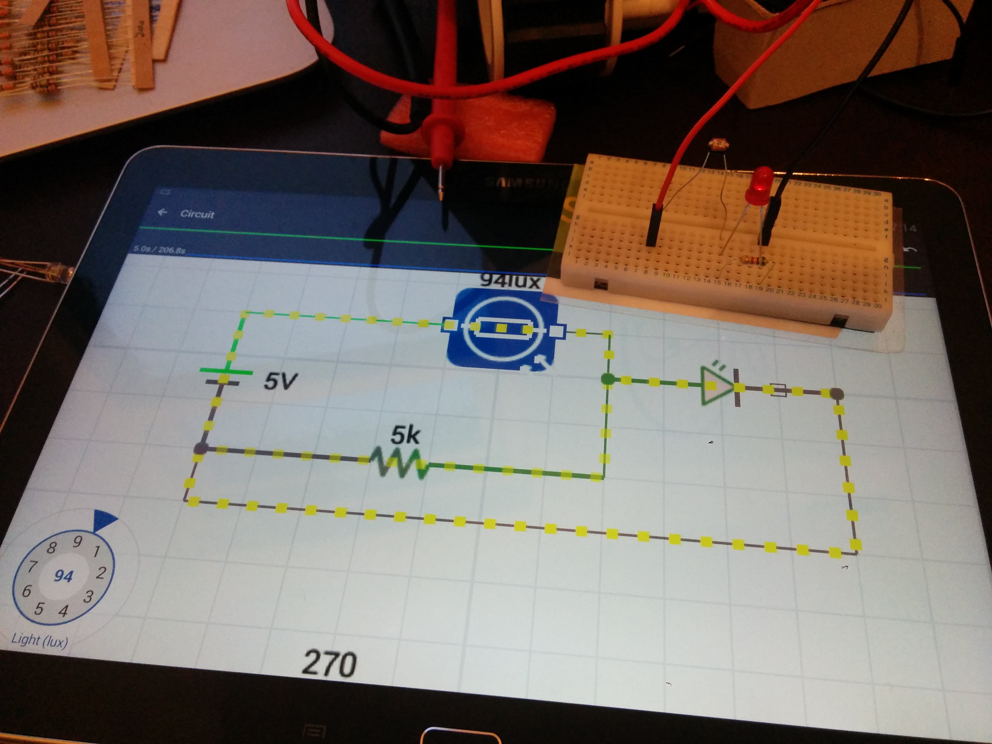
First up was a basic photoresistor circuit, I think I'm correct in saying its a potential divider. The resistance across the photoresistor was around 50k when in the dark. I started like this because it enables me to add one thing at a time, making sure I get it right and then increasing the complexity.
This worked ok, when I shone a light on it the LED lit up and vice versa. The bought line sensor LED was either on or off however this circuit makes it come on gradually, as expected and desired.
Once I was happy this worked I then changed the circuit to send the teensy a signal when the photoresistors (I'm calling this a PR now) resistance dropped. I didn't connect it up as I'm going to go and speak to some friends studying electronic engineering and get it all double checked as I don't want to blow anything up. Once this is done I then need to scale the circuit up to include another 4 of these, I also need to find a way of running the IR emitters from the same voltage source. Currently my design with the IR emitters included leads to them turning off when the PR picks up light; this is obviously going to create a feedback loop. It has just occurred to me that maybe the PR only works with light on the visible spectrum. I will need to test this.
Having done some reading and some of these PRs are sensitive to IR but it can lead to heat build up. This will be added to the test criteria for the PRs I have. For those interested http://www.resistorguide.com/photoresistor/
I had a chat with Ben on Monday about the basic circuit; This confirmed I was on the right track and he also talked me through using a current reducing resistor on the emitter so it doesn't drain the circuit.
Feb 16th. I connected up the IR emitter this morning and this confirmed my suspicions, the photoresistor only works on the visible spectrum. I could use a white led instead of the IR emitter or I could change the photoresistors to photodiodes or phototransistors.
The emitters worked fine and I didn't notice any excessive heat build up.
Another issue I have been struggling with is the scaling up of the system; the teensy should be able to handle one sensor but once four or five are connected with emitters it places too high a demand for current on the teensy. If they are arranged in series they get the current they need but not the voltage; if in parallel then they get the voltage but not the current. (I learnt about Kirchoffs voltage and current laws this week which helped).
I spoke with Raul, a guy I know studying Mechatronics and he said that it is not always normal to have all the sensors on all the time due to the issues I am having. A solution to this is to cycle the sensors so that they come on individually for a short time interval (typically in the ms range). This should improve battery life and make sure every sensor gets the current it needs without affecting the effective response time of the robot. This would require a buffer and some extra code. He also recommended getting a paired emitter and sensor after my realisation this morning that the ones I had bought were incompatible. I think it's dawning on me that the decision to make my own sensor array and use it as part of a proportional control system is a much bigger task than I thought; still, I've started now so I may as well just crack on and pick up the prerequisite knowledge along the way.
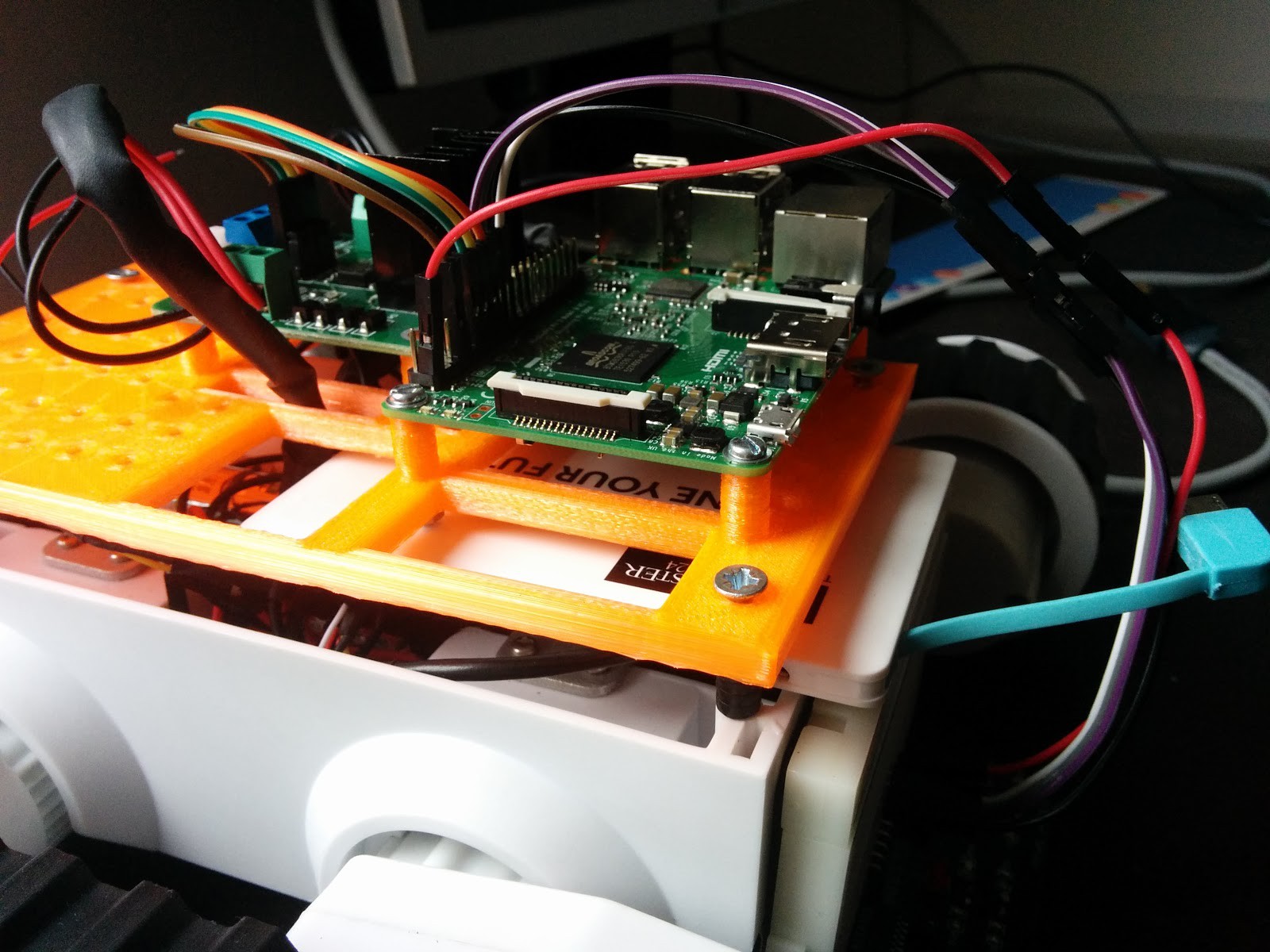
Teensy mount
I modelled and printed a mount for the teensy this week; I had a look at some that others had made and used some of the ideas. The inspiration came from here: https://forum.pjrc.com/threads/25115-How-are-you-Mounting-Teensy-3-3-1
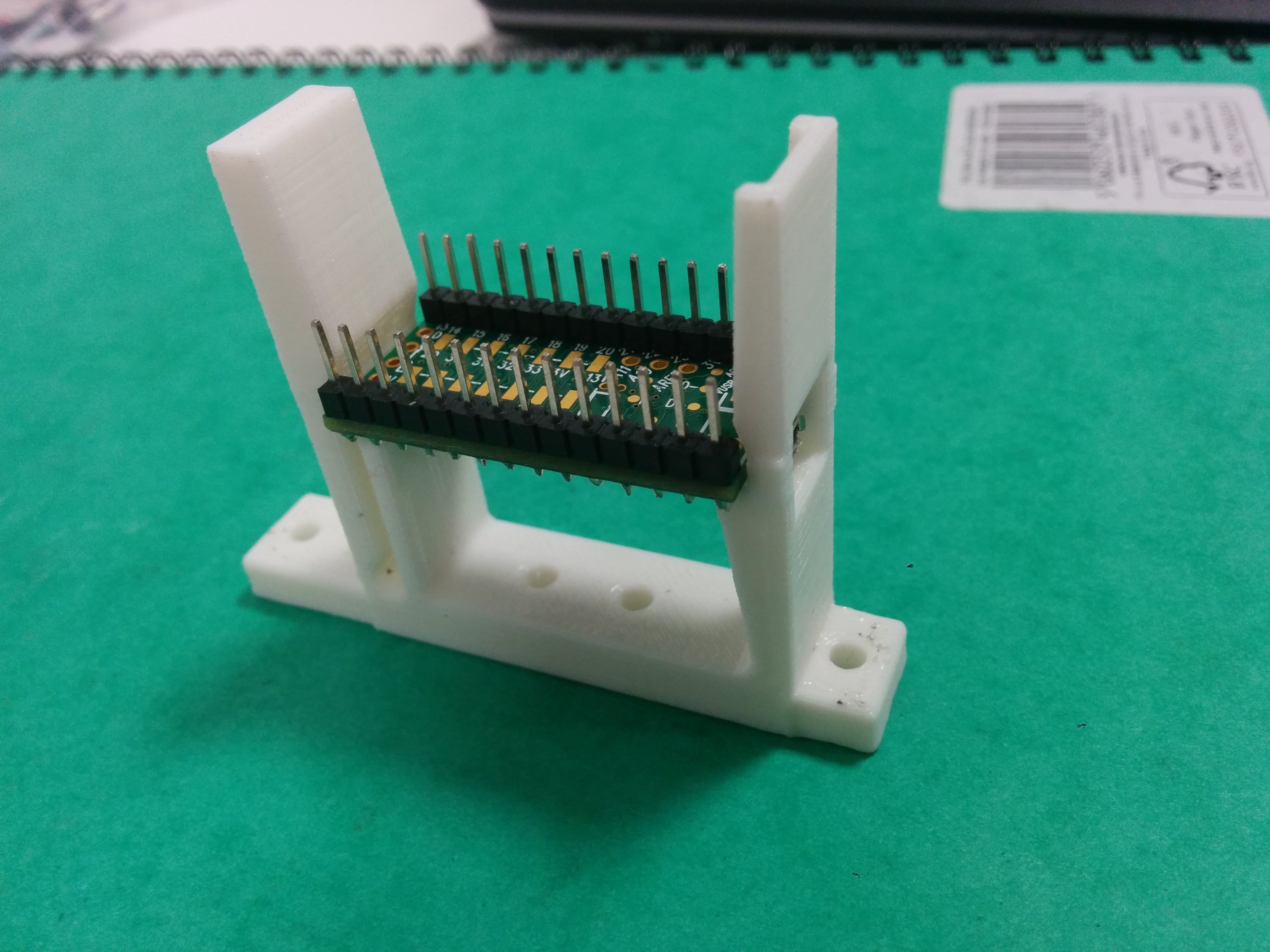
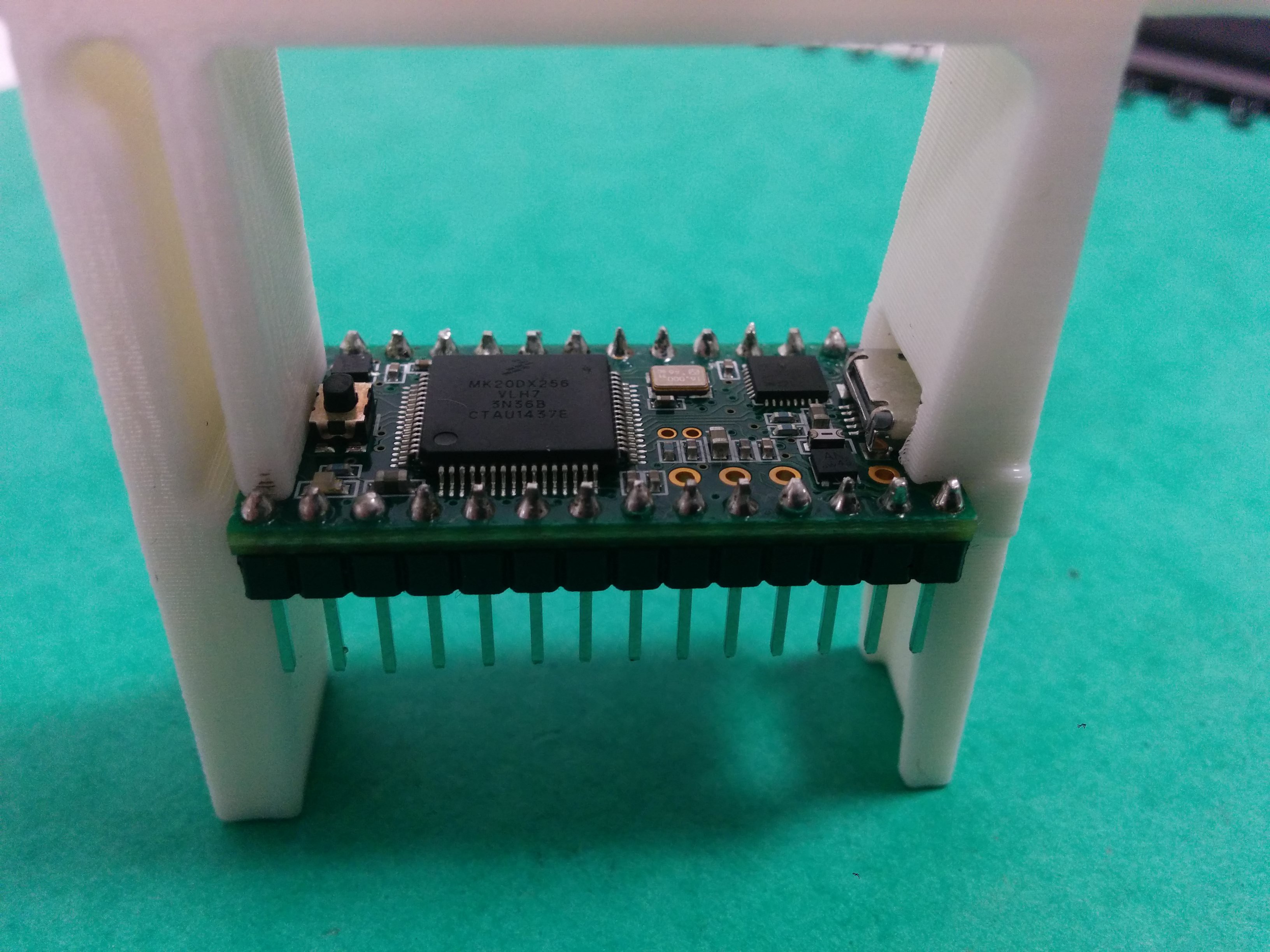
I felt this was a good design, it was easy enough to model and seemed easy to use. Mine would not be a good fit for this because the pins I had soldered on would point down, not leaving any room for actual jumper leads to be connected. I took the basis of that design and adapted it so that a teensy could be installed either way up. The 3.2mm mounting holes are spaced giving options of 10, 20 and 30mm; I also put some in to make it compatible with a pi 2 mount i.e. 49 and 58mm. I like options.
It was interesting printing something which needed finer tolerances; due to expansion in the material the holes shrunk in diameter to 2.7mm however the actual distance between them was unaffected. The way the machine actual lays the material up leads to anistropy in the part. The bond in a particular layer, the x-y plane, is stronger than the bond between layers because the material in the x-y plane is deposited and starts to cool at the same time whereas the next layer will be deposited later and not be in quite the same state as the the previous layer. I think if I was going to do anything structural I would bear this in mind but for this sort of application I don't think it matters.
It's also worth pointing out than when an item is 3d printed it is not a solid object. There will be a solid wall but the inside is a honeycomb structure. This means that you should decide what holes you want and where before printing because you won't really be able to drill them afterwards.
Here it is, stl file in the files section if you want one. Printed on a makerbot at 0.2mm layer thickness, supports and rafts on, 3 shells and 15% infill. It took 40mins and around 11g of material:
Sensor prototype
I managed to get together everything for the sensor and prototyped it this weekend. It consists of 4x tcrt5000 sensor/emitter pairs, 4 leds, 4x 330 ohm resistors, 4 x 10k resistors and a load of jumpers. I found this was a learning experience yet again, it is only the second circuit I have put together and I made more than a few fundamental errors, mainly wiring LEDS backwards (diodes only allow current flow one way) and not reading the datasheets first leading to wiring up the emitters as sensors and vice versa. After a few hours it worked, it could pick up a line on some paper as I waved it over the top. This was slightly overshadowed by the fact I managed to fry 4 LEDs and one of the tcrt5000s. Next step is to see if it will run off 3.3V from the teensy and have a go with the arduino analogue read function. If it doesn't like running off 3.3V then I will have to connect up the ULN2003 buffer to cycle through the sensors individually. Here's the basic circuit, schematic to follow:
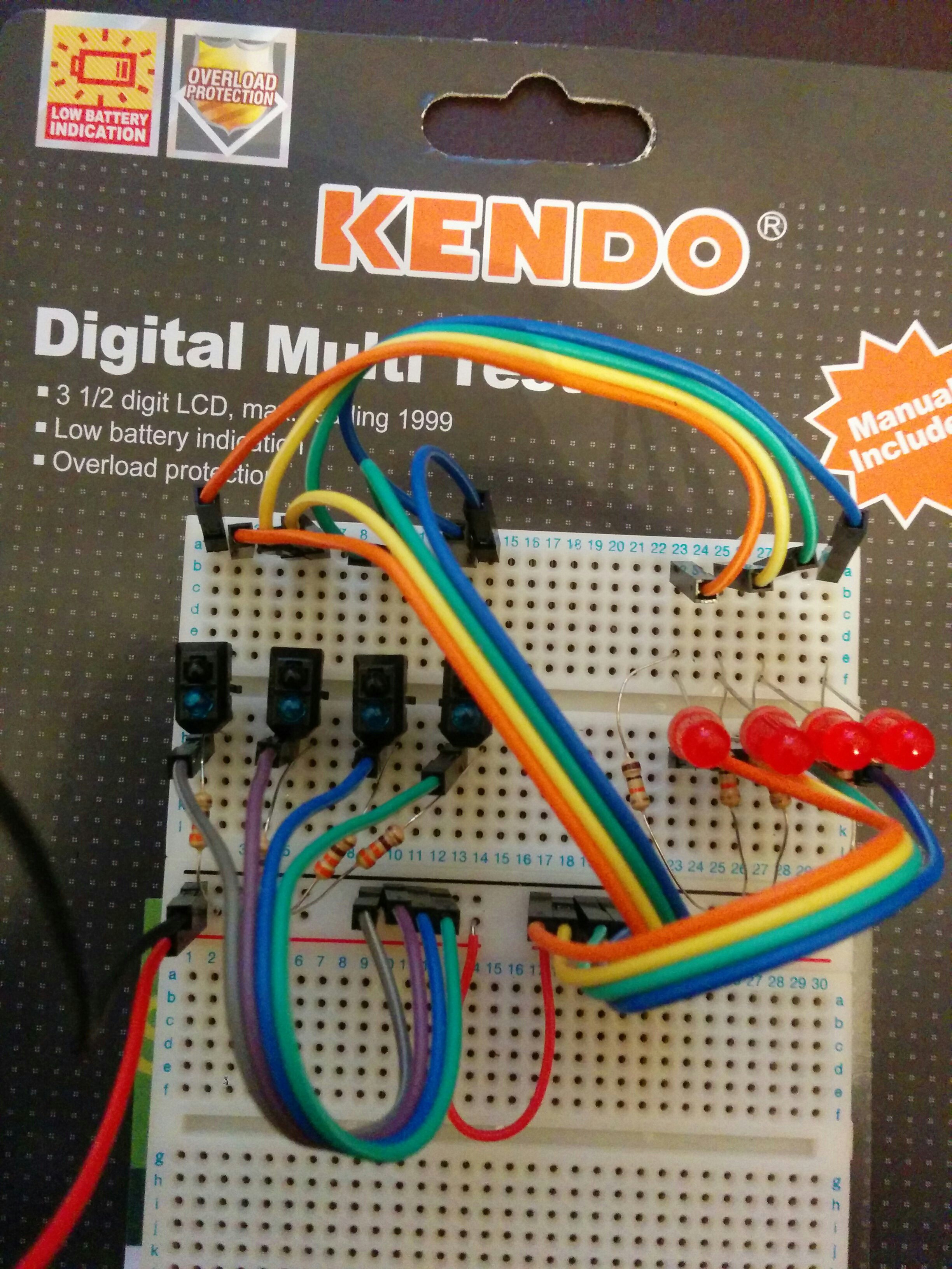
One final thing I learned while doing this is that the motors in the rover chassis are magnetic; I discovered this after searching for about 15 minutes for a strip of 10k resistors and finding them stuck to the underside of the chassis. When it comes to learning theres no way like the hard way!
24-02-16
The sensor array is now connected to the teensy. The red LEDs no longer light up, I don't know why but the circuit seems to work ok. Ben suggested that they are not getting enough current; the LEDs aren't a deal breaker as the circuit works; it has put a dampener on my dream of having a robot like knightrider. I wrote my first arduino sketch which I managed to get together using only the arduino library pages. The arduino language (C?) is now the third language (if matlab counts as a language?) I have written a program in and I think I like it; it's a lot less shouty than the python used on the pi. It took me a few minutes to realise why none of the analogue functions worked at first: our transatlantic friends who wrote the arduino language seem to have a problem with spelling. If I was going to start this whole thing again I'd probably start with an arduino; its a lot easier to get started with.
The program measures the inputs across 4 pins and weights them to give a +ve or -ve value which is then summed and scaled and used to control pwm to one or two pins. The term 'weighted' means that the far left would be multiplied by -2, inner left by -1 and then the inner and outer right by 1 and 2 respectively. When these are added together you get a reading that is positive or negative and the magnitude is proportional to how far away from centre the line is. This is where the P from PID comes from. The scaling is because the analogue reading is from 0 - 1023 and the PWM is 0 - 255. At present the scaling in my code is off because I just divide the sum of the weighted readings by 4; I have read about the 'map' function which scales one range of numbers to another one. I intend to use this in the next iteration of the sensor/code. Tis just made me think about the definition of a sensor, is it just hardware or is it also software? Anyway, I'll leave the philosophy to the art students.
I ran a 2 second delay and printed the values on the serial monitor so I could make sure I was getting the readings I was expecting; the delay will need to be changed once it goes into the rover. I connected 2 leds and used the analogue write function to turn them on and off depending on the values calculated. They were either on or off but I just looked at the teensy pinout and the pins I had connected them to were only digital write pins so theres another lesson: use the correct pins. Just because it is an analogue pin does not mean that it can support the analogue write command. A final thing that it took a while to get to work was using the analogue write function, this is the section of code that works:
if (linepos > 0)
{
analogWrite (1, linepos);
}
else if (linepos < 0)
{
analogWrite (2, linepos*(-1));
The thing to note is that when using the sensor output to set pwm, if you are using a negative input value from the sensor for the pwm then multiply it by -1 or it will try and set the pwm as a negative value. I'm not sure how this would work with a dc motor but it definitely doesnt work with LEDs, as I discovered on Sunday.
I'm going to try and expand it to 6 sensors and incorporate the ULN2003 buffer next.
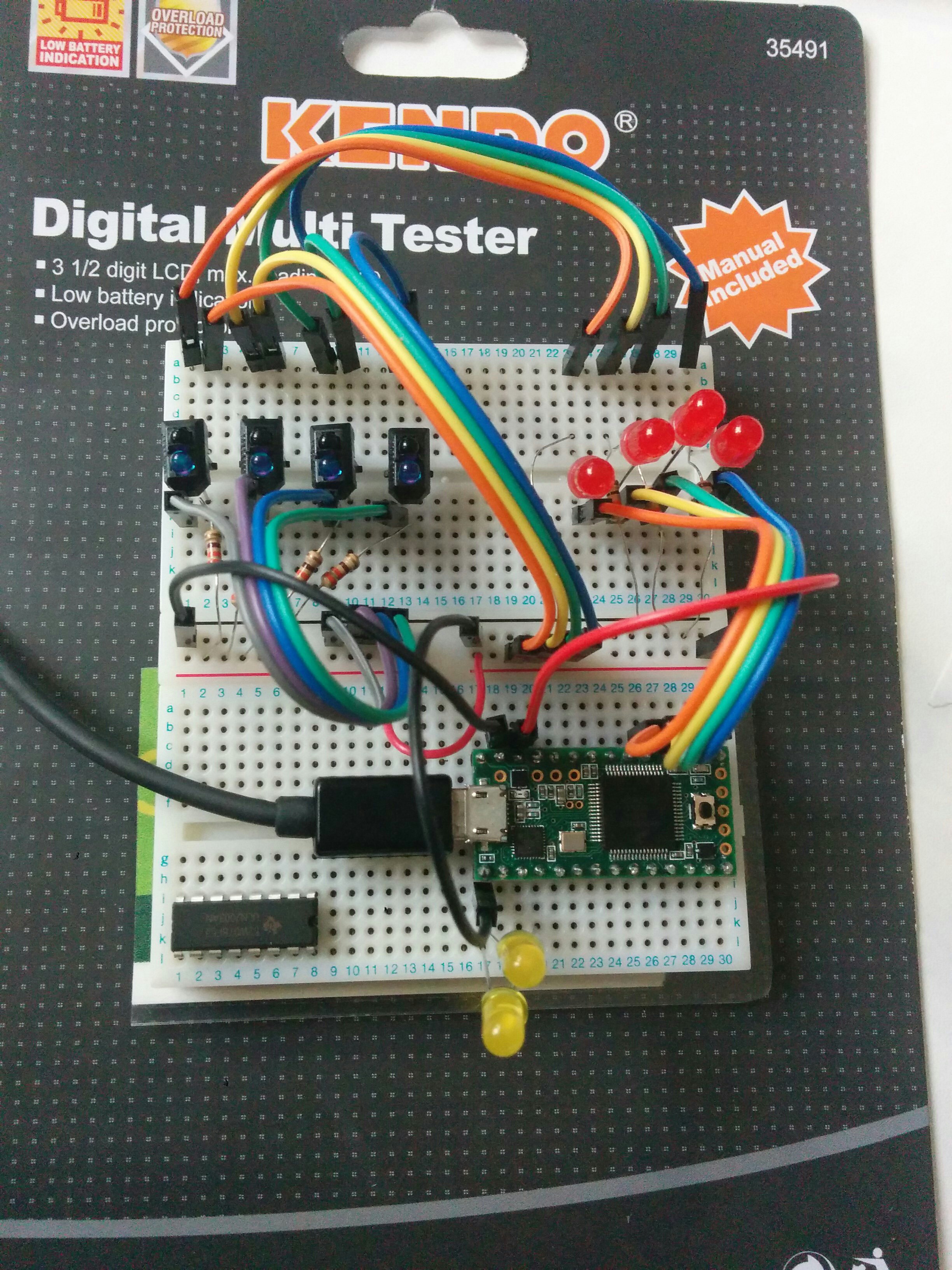
Today's code is in the files section (analoguepwmconcept) and the breadboard now looks like this, not sure if the teensy needs a ground for digital and analogue but one thing i'm doing now is grounding everything!:
25-02
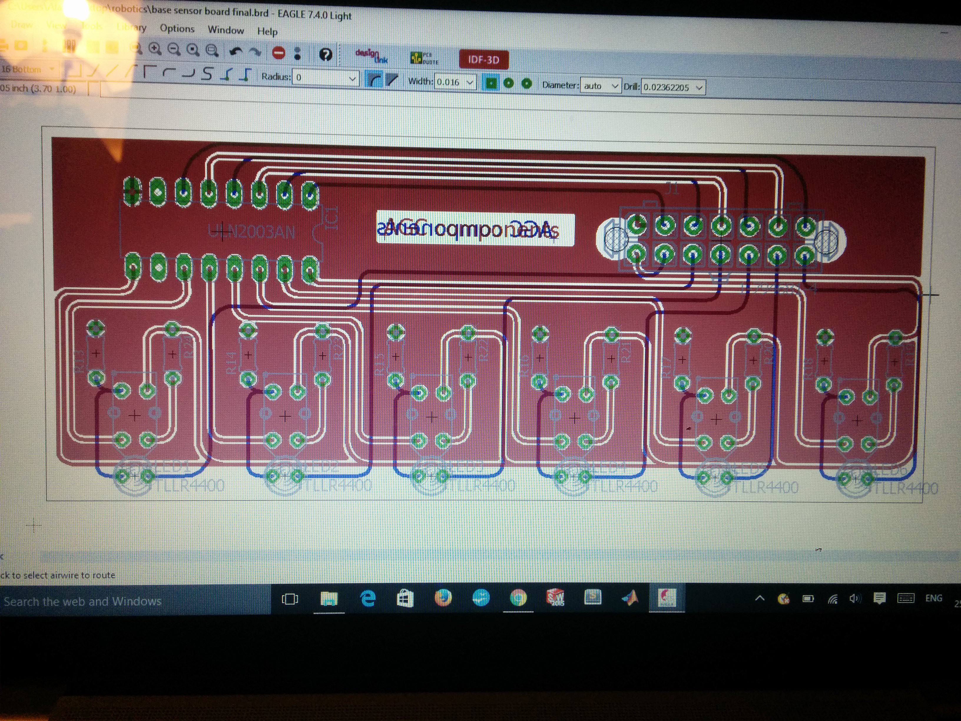
I had a go at eagle today, it seems fairly intuitive once you get your head around it. I quite like that you can change the schematic and it automatically updates the board.
I included a ULN2003 buffer on the board; this should help with the drain on current and also it should help with crosstalk. I had an idea about shielding each sensor from the next but if the sensors are cycled and readings only taken for one sensor at a given instant then there should be no confusion between them.
I'm not sure if it works yet, Ben is checking it over before it gets sent off for fabrication, there's also the small matter of populating it and seeing if it actually works.. Once I know it works ill share the files, here's a sneak preview:
ideas time:
mount for the sensor: instead of bolting it in, have a slot and click (similar to teensy mount). Also, have tabs around the outside to attached a shield to protect from interference from surroundings. I'm thinking the shield could be a piece of an old bicycle inner tube so its is not reflective and is flexible if ground contact happens.
Have a height adjustable sensor using a servo; this could be manually operated from a pot or there may be some way to use the sensor readings to determine the height and adjust automatically (total reflectivity reading/us sensor pointed at ground may be too short range). The servo moves in an arc so this could be used to move the sensor in when the rover is in short wheelbase/high mode and viceversa. use a simple linkage to ensure sensor stays parallel to surface.
Code: use sensor data to determine path if it comes to a junction, set threshold reading and designate as on/off. If all off then maybe a junction. If all on then maybe line has disappeared - determine actions at these points. need to integrate into pwm code so there is no conflict.
derivative: can be used to give a weighting to pwm settings but can also give an idea where a line should be should the robot understeer and lose the line. use this to help find its way back.
Wheelbase: shorter should turn quicker so the speed could be increased. change gearing in gearbox to increase speed.
pan mount for us sensor to detect if an obstacle is in the way. use this as a failsafe rather than determining primary behaviour.
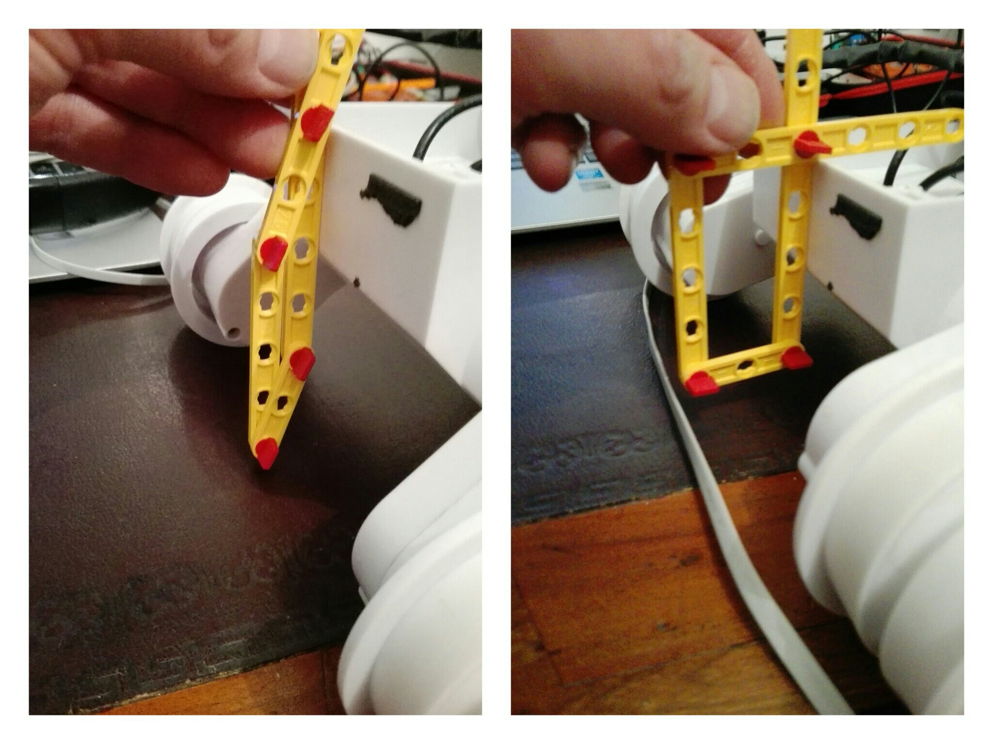
02-03 It's not a toy
I had an idea about a linkage to adjust the height of the sensor at the front, the chassis has adjustable ride height/wheelbase so I thought it would be appropriate to build in some adjustment for the sensor. I got out the fishertechnik I bought for my foundation year project, a passive dynamic walker (informal write up to be done over summer, video here ), and put together something simple. The idea is that when the chassis is in high mode the sensor is brought in and down so that it is close to the ground but does not stick out at the front. The opposite should happen when the chassis is put in low mode; the wheelbase extends so the sensor will need to come up and out. From reading about line sensors it seems that the further away from the axis of steering the sensor is, the better it is at reacting to changes in direction. I need to model a mount and linkage on solidworks but this seems to what I should be aiming at:
I would like to have this actuated with a servo controlled by a potentiometer so it can be set up quickly, this would also give me the option of automating it later on, if I wanted to. I'm not sure how I would do this, the distance from the chassis to the ground is not massive and I don't think an ultrasonic sensor would be effective at such short range. I don't need to worry about this now though...
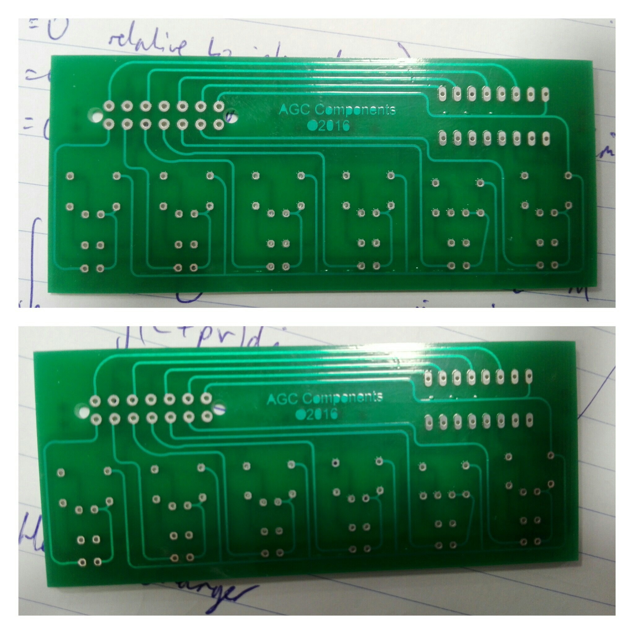
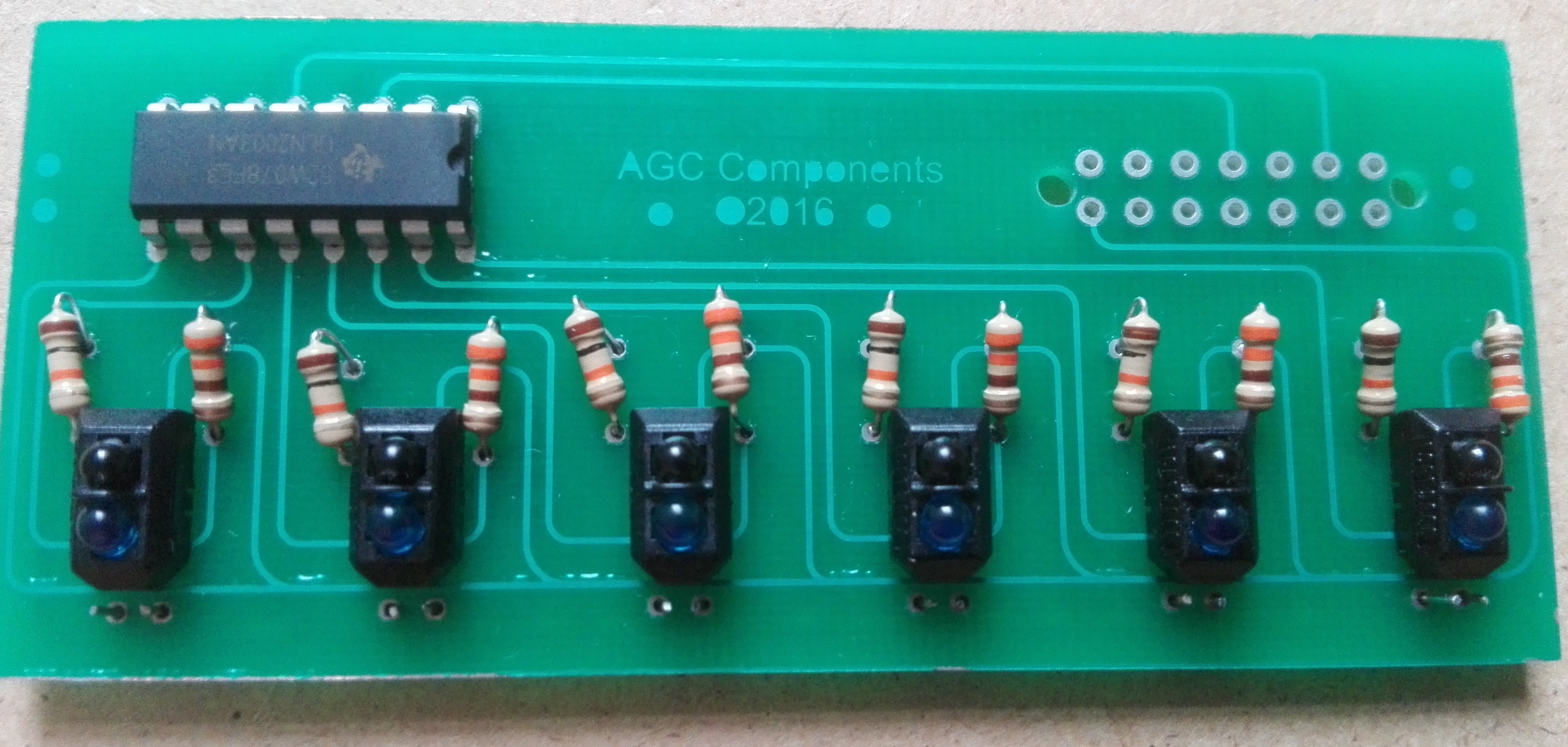
PCB
I picked up the PCB yesterday, all looks good and I'm looking forward to getting all the bits soldered on. I also had a chat with Pepe and Tom about laser cutting, the material they showed me looked much more appropriate for the linkage I have planned given that it is both stiffer and has a lower coefficient of friction. Its limited in that it can only be used with 2D patterns but I think that should be easy to design around.
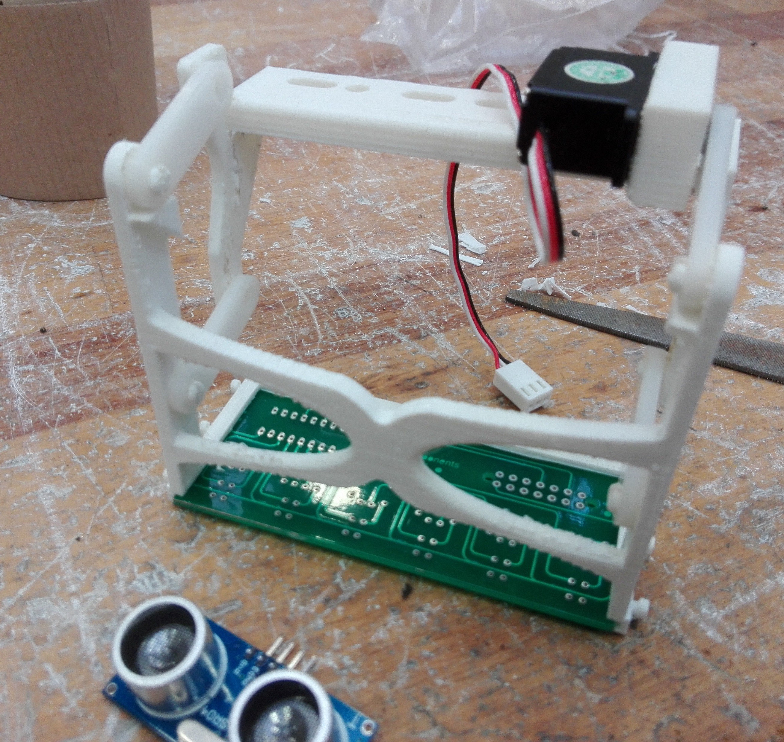
Sensor mount printed 08-03
I modelled a mount for the pcb that would enable it to move up and down, because it moves in an arc it helps to stop it protruding out of the front of the rover regardless of wheel height. I got the linkages laser cut, this is a very quick and cool process, it took less than 30 seconds to get the link plates done. I had modelled the splines for the servo myself and the plate was a bit loose on the servo shaft; Tom came to the rescue (again) and gave me a servo from a different manufacturer which fitted perfectly.
The printed items seemed more brittle than the teensy mount and unfortunately I managed to break 2 of the 7 tabs when attaching it all together. I'm a bit disappointed by this because I will have to fix them up with a screw and a washer; I was hoping to eliminate the need for tools wherever possible and this will now sadly not be possible.
The pcb was a good fit, as was the servo after some filing. Neither of these will need any extra retention devices as they are a snug enough fit to stay put. An after thought is that I can mount the ultrasonic range finder on this, it is a nice fit on the front struts and I should be able to attach it with some twisted wire.
I would share the file but a) its not perfect and b) its specific to the custom pcb and rover component mounting board I made so it's probably not much good to anyone other than me.
Here it is, more pics to follow once its on the rover with its snazzy rubber shield, and maybe a populated board if I get time tomorrow (I have 4 pieces of coursework for my actual degree due next week so they have to take priority):
09-03
I attached the mount last night and in doing so managed to snap off another tab for the link plates. Interestingly, all of the broken tabs were on the back section of the mount. I went to speak to Dan in the 3D printing lab and, as I suspected, the 2 sections had been printed in different orientations. The front section had been printed with the layers aligned with the axis of rotation of the plates whereas the back section had been printed with the layers aligned perpendicular to the axis of rotation (i.e. in the plane of rotation, hope this makes sense). This had a significant effect on the flexibility of the tabs, resulting in the snapping described. The top section of the rear mount was a good fit in general terms on the chassis but once I started to attach other pieces I realised that there were a few issues with 2 components wanting to occupy the same space. The upshot of this is that I will need to modify the design the backplate and reprint it, either with redesigned tabs or just make sure that it gets orientated correctly in the printer. We learned about 3D printing anisotropy in our lecture last week and I feel that actually seeing the effect of this has been very handy.
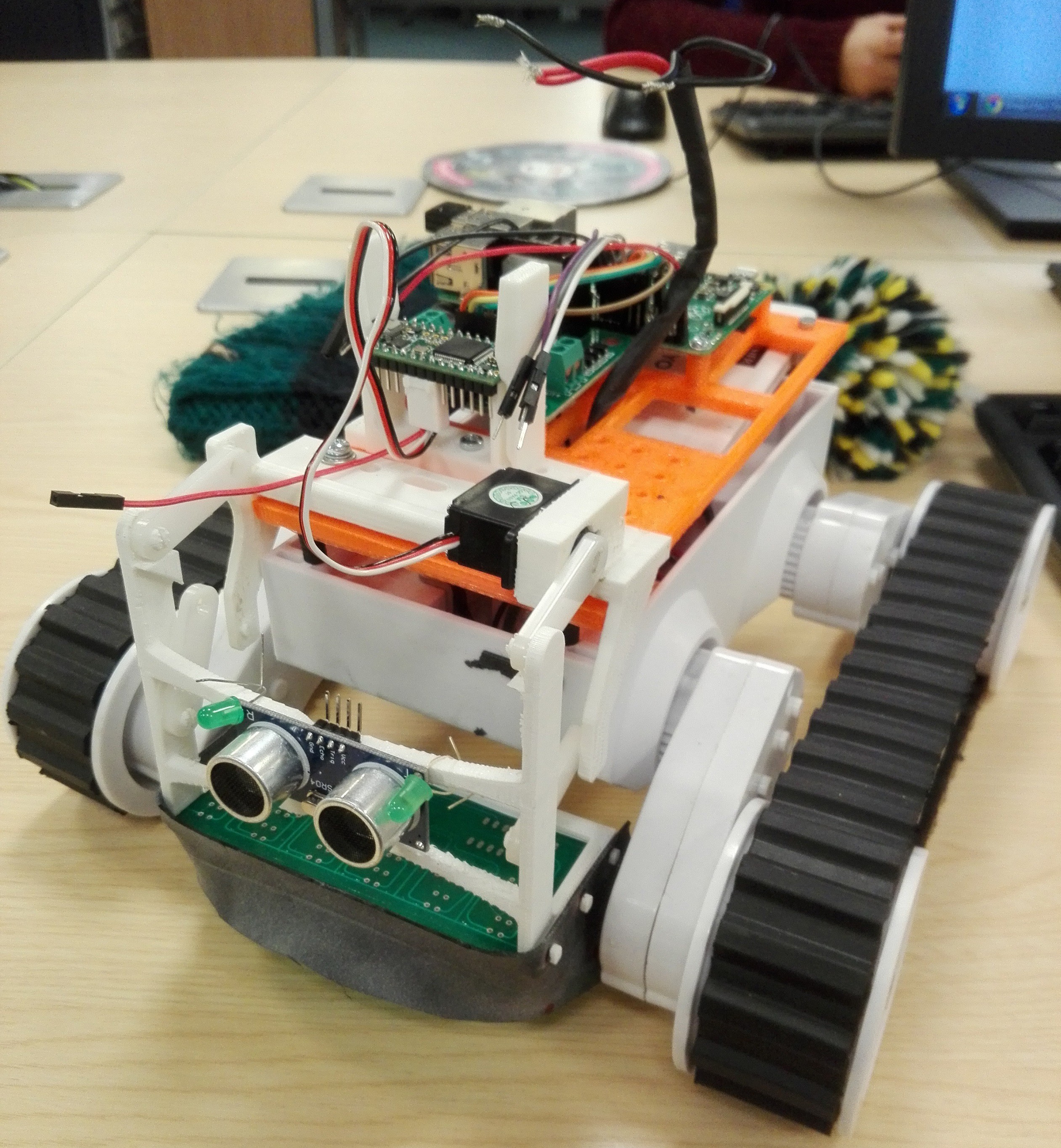
Here it is, including a rubber shield made from an old inner tube:
21-03
I've not posted any updates for a while as I've been doing some work for my actual degree and most of the stuff I've been doing on this project has been reworking the front sensor mount and learning more about 3d printing, specifically what happens when it goes wrong.
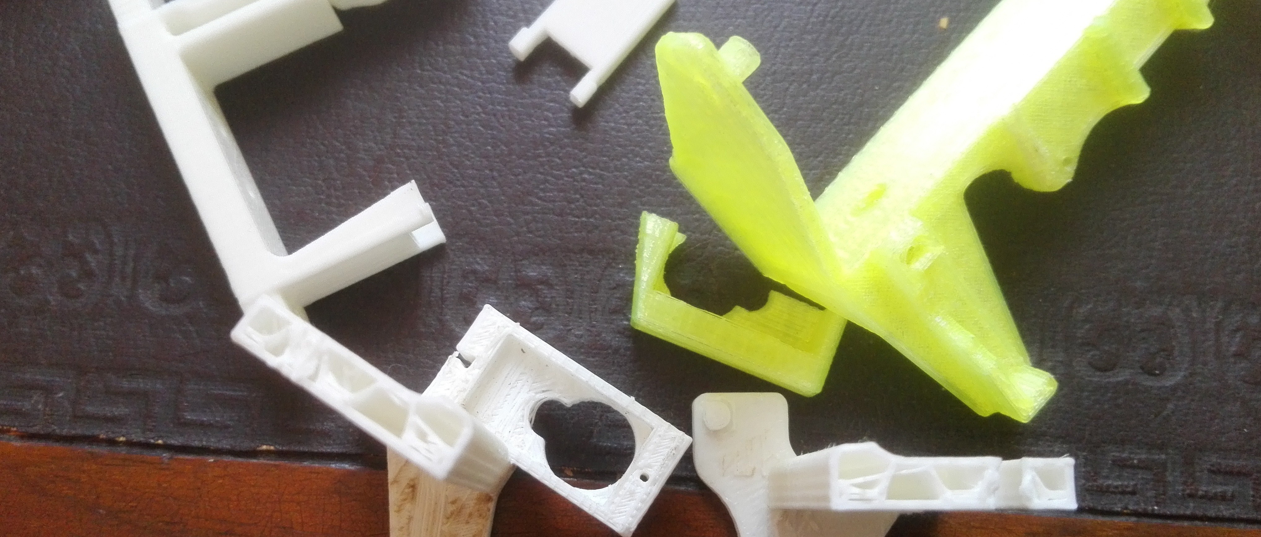
I redesigned the back section of the mount 3 times, each time it was printed a different way up so the layers and support structures were different, also the material was different. All the material used is a thermoplastic made from a maize extract; even though they are from the same manufacturer, the additives to give it colour changed the way it behaved. This had a significant effect on the mechanical properties of the printed part; the white stuff had some flex in it but the fluro yellow stuff seemed to be quite brittle, The gold stuff seemed to be in between and seems to be holding up nicely. The teensy mount I printed also snapped, unsurprisingly on the same plane as the way it was layered up. One benefit of these snapping parts was that I could see what the stuff was like on the inside, It is hollow with a hexagon support structure as shown here with my pile of broken bits:
The changes to the back part of the sensor were to the orientation of the servo and I changed the design of the tabs for attaching the link plates. It was also designed with the printer in mind; I knew where I wanted the strength to be from where it had failed (see above picture) so I tried to shape it in such a way that it would be easiest to print the way I wanted it printing. It left some pretty scruffy looking details where the part was printed on the supports but it seems to be sturdy. I also stuck the breadboard back on the front; the teensy mount has broken and it also does a nice job of keeping the link plates in place (an accident rather than by design).
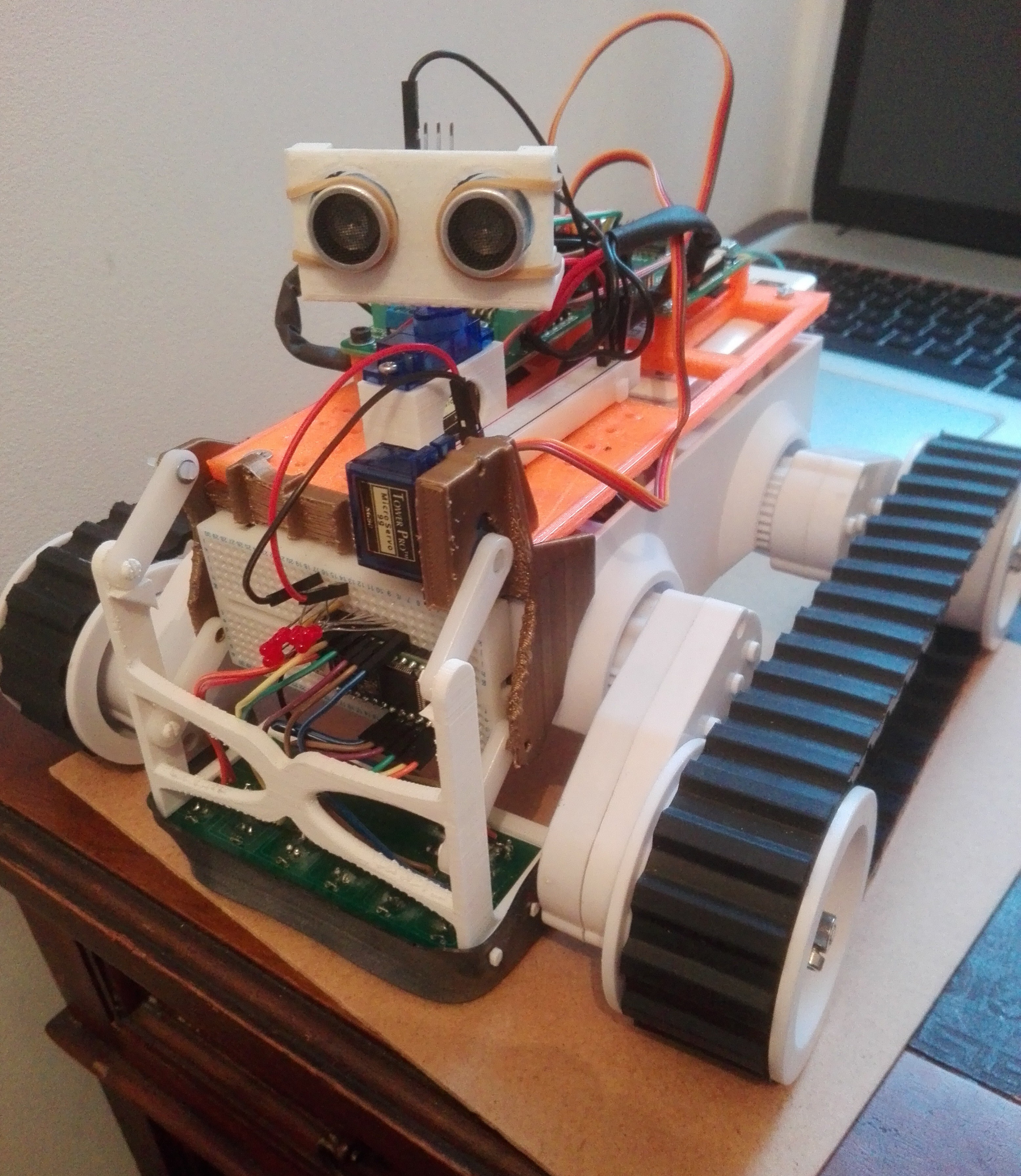
I was going to mount the US sensor on the gold section, it has holes for a 1mm bolt (these exist) but I think now the teensy is on the front and I've got a load of room on top, it's time for a pan mount for the US sensor.
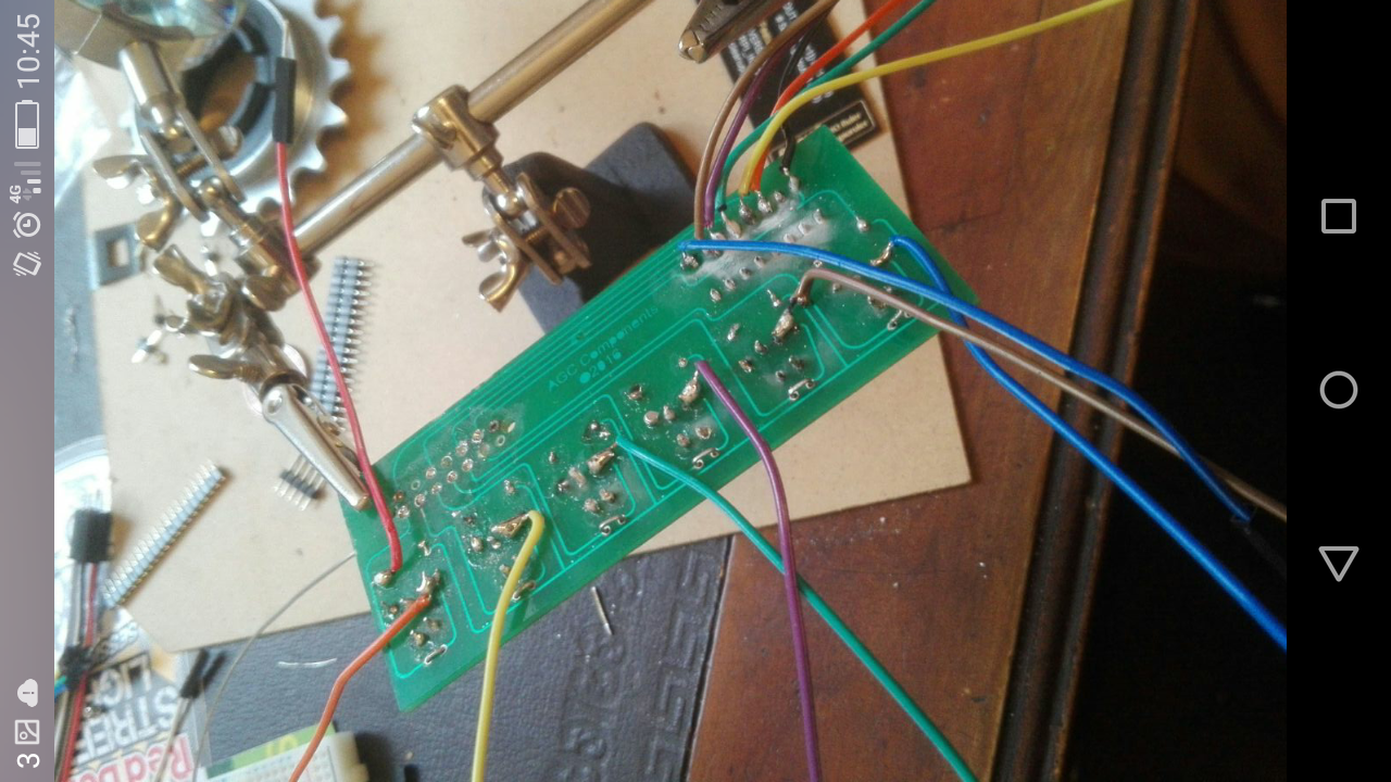
Finally, I got the board populated with everything but jumper connectors. I'm not sure who came up with the design for a soldering iron, they seem to be specifically designed to burn you as soon as you hand forgets it's not holding a pencil.
I left the leds off because the voltage drop across them meant there was virtually nothing left to read once the signal got back to the teensy, this resulted in problems with scaling for pwm. I have found a way to have both a usable reading and have flashy lights but it requires the board to be reprinted so I'll have to just go with the setup that works.
further ideas: Connect up the encoders to improve the accuracy of the proportional control - build in calibration to a setup cycle?
if the encoders can help establish position then maybe the data from the IR sensor could be used to map the course?
have a visual display (eg 6 leds) on top to give approximation of sensor data, to replace the omitted LEDs on the pcb.
1st April
Having spent the last week preparing for intern ship interviews I have not got much blog done; there has been some progress though. I designed a servo mount and printed a sonar mount I got off thingiverse. The mount I designed was perfect but the sonar mount was a funny fit which led to a novel way of mounting it: an elastic band. seems to do the job. I managed to get some LED's parallelled up with the sensor outputs by cramming them onto the breadboard. I did have a problem when I soldered the jumper pins onto the board, I soldered them on the wrong side. Once I had got them back off it was near impossible to solder them onto the other side so I just attached the wires to the nearest component I could:
I have since found out that there are things called desoldering guns and desoldering braid, I think these are going to be an essential bit of kit.
All I need to do is check this still works, work out how to get the teensy and pi to have a conversation and I'm good to start tuning the controller, which I'm sure will not be easy:
I spent the day playing around with this, I removed the LEDs because, although they worked, they were not very bright. They also got in the way. Also, I'm not sure the height adjust servo is going to be a good idea; having the teensy on a breadboard at the front means that the mount and the jumper leads are competing for the same space. I'll leave the servo on because it's still very easy to adjust the height and it stays put once you've set it.
Initially I was getting low readings, I found that sticking a small delay after switching a sensor high was all that was needed, this still gives you around 16 position checks a second. If you're not using a buffer I don't imagine that the delay is necessary:
digitalWrite(10, HIGH);
delay(10);
int p2n = analogRead(A5);
Also, I found that the sensor worked with both 3.3 and 5 volts but I got better results with 5v so I'm sticking with that.
I had a problem with sensors 2 and 5, I couldn't get them to give a reading above 15 (out of 1023) using the analogue read, the average when the rest were reading max was around 6. After loads of checking and asking around I came to the conclusion that I had fried them while soldering up the board. Luckily the 2 problem sensors are symmetrical so I figured I'd try and code my way around it. I thought about mapping the individual low values to a larger range (0-1023) but in general this didn't work due to the values being too low.
I will keep this idea in the bag though, I might build sensor calibration into a start up routine, e.g set the sensor over a uniform part of the surface the line is on, take a max value for each sensor (call this value a) then map the range (0 - a) to (0 - 1023) for each sensor, giving a more accurate overall reading.
managed to get the sensor working with only 4 sensors, reckon it might behave a bit funny but that's half the fun. I also managed to get a derivative value to help weight the pwm, I'll post today's code at another point, I've been staring at a screen so long I'm convinced that error is not meant to be spelt like that. It doesn't even look like a real word any more.
update: todays code is in the files section, not the finished article but it works. It also shows one of my favourite thngs to do, add a delay at the end of the loop so it's easy to read and assess whats gooing on via the serial monitor.
2nd April
I switched the pi back on this morning and managed to setup remote desktop thanks to Josh at uni, it was dead easy, and life changing! For googlers REMOTE DESKTOP ETHERNET RASPBERRY PI WINDOWS:
Using the normal monitor/keyboard/mouse arrangement turn on the pi and type
sudo apt-get install xrdp
then type this to find your pi ip address (its a capital i at the end not lower case L)
hostname -I
write this down *** alternatively download angry ip scanner and use that to find the ip from your laptop**
get ethernet cable and connect laptop and pi;
on laptop: open remote desktop app in windows, type the pi ip address in
You should get a window asking for your pi username and password, type these in and you're good to go.
I'm now in a position to try out getting the 2 processors to talk, which I will do this afternoon.
4-4-16
I had a go at setting up comms between the rpi and the teensy but didn't have any luck. I was trying to use the serial communication method now that I don't need the serial port on the rpi (if you use remote desktop then the rpi doesn't need to give an out put to a monitor - disable the serial port and you can use it for something else).
It also occurred to me that my proportional control needs tuning, I think maybe it's better to see this through before trying to setup i2c, theres no point them talking if they dont know what they want to say yet. I did some more reading on pid and realised that there is an arduino library with this function built in. I think this has helped me understand a bit more about how these things work and how I can use this to structure my code. I've had a quick play with the PID library and it gives an output of either 0 or 255. This is a less accurate proportional control than the one I made using if + and + or statements before christmas. The decision now is to try and tune the pre-written code or carry on with my own pid code...
I've decided to carry on with my code and have had some success with this. It's been a bit of a challenge turning one error value into a pwm setting for 4 pins (left and right, forward and reverse). Interestingly, if I try and run the motors with a pwm of less than 50 the motors don't turn, they just hum. I remember from spending a day or two at a motor rewind place years ago that this is not good. For this reason I am going to map the pwm range from 70 - 255. I'll also need to tune the adjustments so they actually help it follow the line; I think it's better to over compensate to start with so it at least follows the line in a fashion. I got this to work just before my wife Jane came home which put me in a very good mood.
5-5-16
I had an idea this morning, instead of setting up serial or i2c communication I could just use digital high and low signals. If there is an obstacle in the way the pi tells the teensy to stop sending pwm and takes over the running of the motors, the teensy can still sense a line and if there is one it sends a pin high to tell the pi its found a line again. This could all be done using digital 1/0 signals rather than sending packets of data.
8-8-16
I made a load of progress over the last couple of days. I was getting fed up with the rover battery pack being inside so I designed and printed an external battery box, there is an stl file in the file section. It enables you to run a mounting board on tom and have access to your batteries when they die without dismantling the whole thing:
I've also managed to get the sonar and its servo working. The servo is jittery as hell but seems to give a good enough reading to do something with; I wouldn't trust it to do anything precise though.
I've also got the two processors talking, I used the digital write/read functions just to send a message from the teensy. If there is a low reflectivity reading on a sensor then that denotes a line. If the sensor has picked up a line it tells the pi by setting a pin high (I used the led pin which also gives you a visual), if the line disappears then the pin goes low. I'm pretty sure I can reverse this by getting the pi to tell the teensy if there is an obstacle in the way. The idea is that using these yes or no style inputs I can let them make the decision about who controls the motors. If there is a line and no obstacle then the teensy can crack on, if there is a line and also an obstacle or no line and an obstacle then the pi can take over until such a time as the teensy picks up a line again.
14-04-16
My pi stopped working before I had a chance to get the rover moving properly so I had a go at just using the teensy. It follows a line pretty well and stops at obstacles. I decided to stop and check for an obstacle every couple of seconds or so because the rover kept losing the line if it was done every loop. It does sometimes calculate a distance of 0 for an obstacle so I'm going to need to code my way around that somehow. Here's a vid of it following the line then stopping once its at an obstacle:
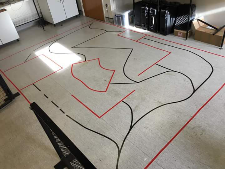
This week we also got a look at the course, theres a couple of tricky little bits to navigate eg the dashed line sections and some junctions that could send it back to the beginning. the red bits are the outline of walls/obstacles/ramps/uneven sections:
19-04-16
This weekend I managed to get the rpi to control the chassis in a kind of random explore setting. The initial idea wasn't to have random movement but I was struggling to even start with the code, it either only did one thing or did nothing at all. I was now at the stage where the teensy could follow a line and detect/avoid obstacles and the pi could randomly explore the course without bumping into anything.
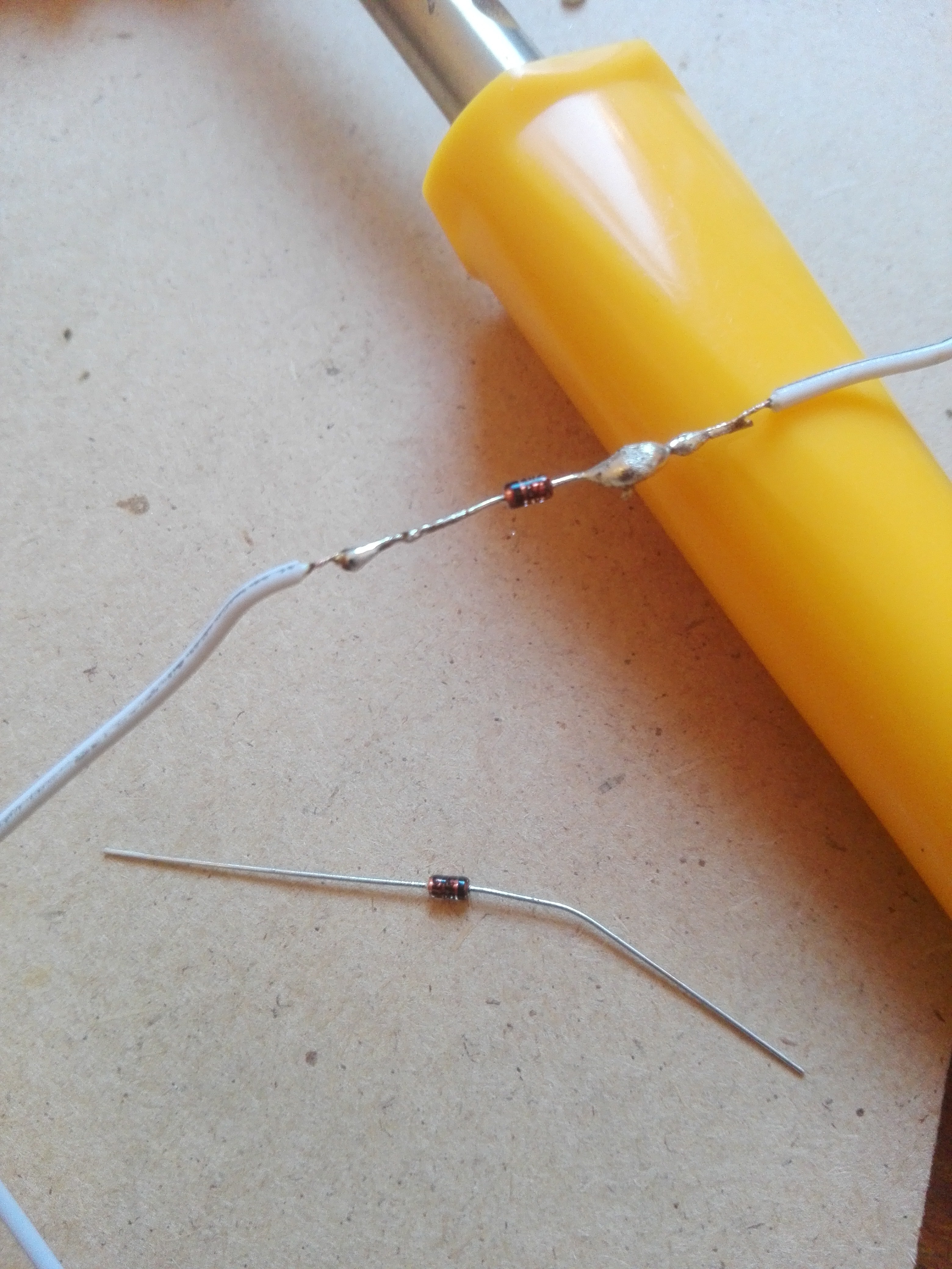
My problem was that if I connected both processors to the motor driver, neither of them could make the rover go. This was because the logic signals bypass the driver and just go to the other processor. DIODES: the solution to this was to put some diodes inline between processors and driver. They are non-return valves for electricity. Once these were installed I could get the processors working together. they look like this, please excuse the sloppy soldering:
While each program seems to work fine on its own the rover is a bit glitchy when they're all run together, there seemed to be a bit of a lag on line detection so I had to slow the motors down when the pi was driving. I did this by writing some crude pwm stuff into the code:
Pseudocode:
forward(); delay(2 ms); stop(); delay(20 ms);
have this ^ looping while pi is telling it to go forward, slows down movement enough to pick up a line. I thought about using the pi's pwm but after playing with it on a servo I've come to the conclusion that pi and pwm don't play well together.
Basically, if there is no obstacle and no line, the pi drives. any other situation and the teensy drives either by line following or obstacle avoidance. The teensy is always telling the pi about line/obstacle detection whether its driving or not.
I set up a test in my dining room and it seems to think the knots in the wooden floor are lines which throws it off a bit. I'm not too fussed about this as I can tune the line detection to the floor where the competition will be p