 julien
Project Status
- Designs finished
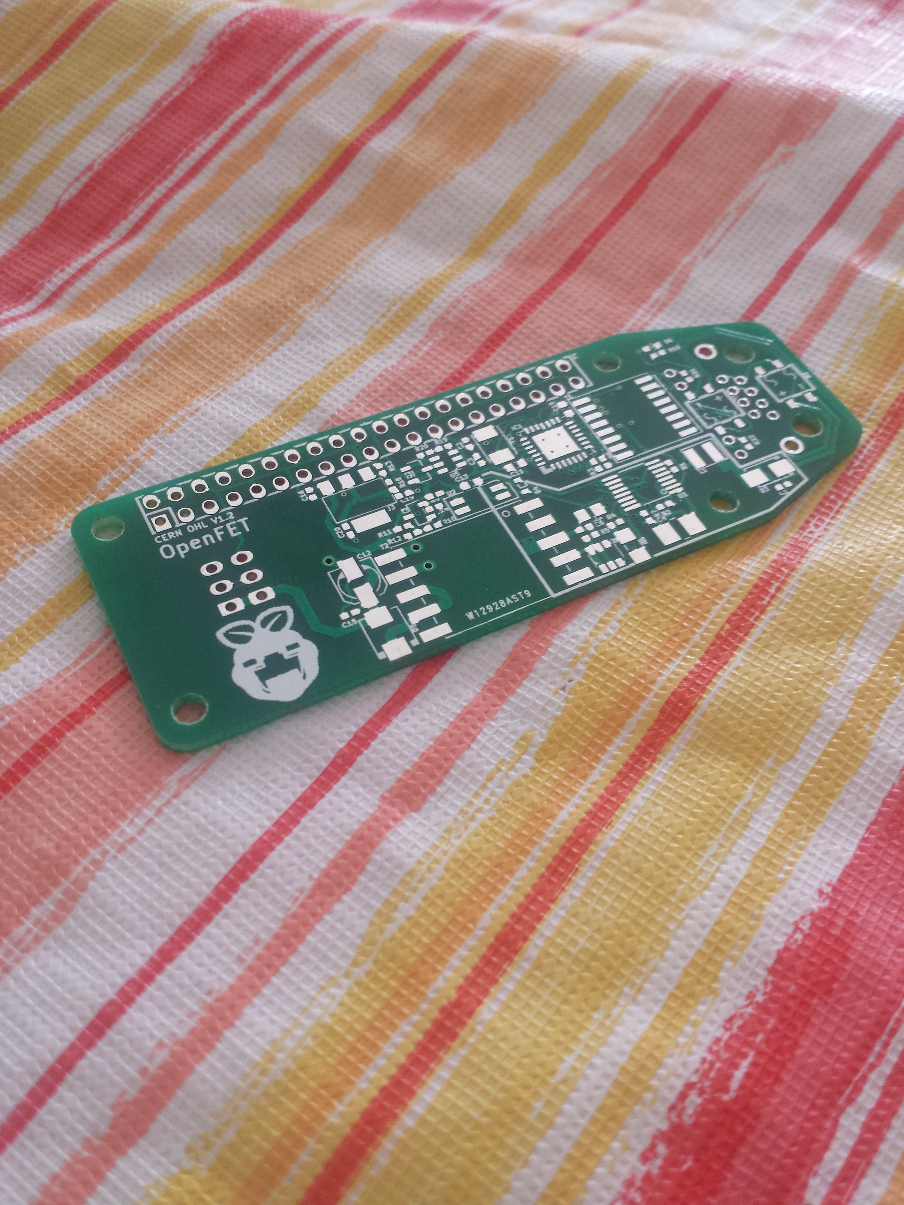
- Waiting on boards for first prototype
- Docs almost done
Concept
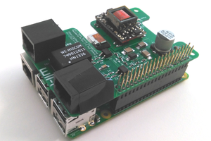
Ever since the Pi Zero arrived people have had issues with Wifi and the USB connectors. We have seen a good deal of people hacking on USB connectors and Wifi modules. I think that using the Raspberry Pi as a computer has had to many people focused on the applications of using it as small desktop. If you want a small computer just use the Raspberry Pi 2.
I wanted to use the Raspberry Pi Zero in a different way. I wanted to enable the Raspberry Pi to easily and safety be used as a Linux machine that you can be implement as more than just a computer. Putting the Raspberry Pi Zero on a PoE injected network allows you to do all kinds of things with the Pi. The only draw back is the slight increase in system cost (and even that can be argued for)
- Power and communicate with the Pi over a single cable
- High reliability system design
- Power external features with the remaining power (about 12W!)
- Centralized UPS system (each Pi doesn't need its own battery)
- Pi can be placed far from PoE switch or existing network
- You do not need to be an Electrician to install
What is PoE?
Power over Ethernet is a method of injecting power into an Ethernet line and recovering it on the other end while making no disruption to the data on the line. PoE has been used for a long time and you can get PoE routers and injectors from any local computer store.
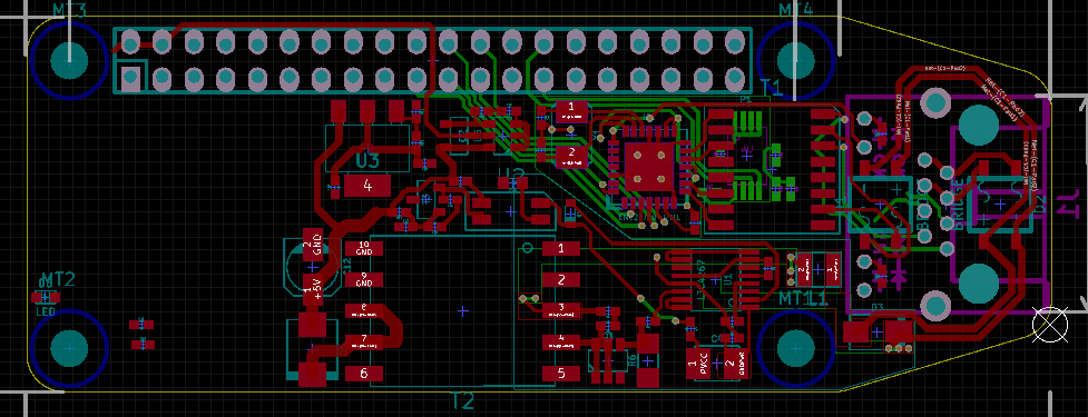
Board Design
The design of the hardware for this device is critical because it provides the backbone for all of the Pi's functionality, mainly power. When I first had the idea of putting the Raspberry Pi Zero on PoE I first went hunting for the best PoE solution. I wanted a system that could fit in the Pi Zero board size and was also simple enough that people wouldn't be afraid to develop with it on there own. Some of the main features that where considered at the beginning of the process where;
- current limiting for the PoE (may be seen in some applications)
- PoE isolation. Most cheap modules don't do this and it could kill the Pi
- resettable fuse
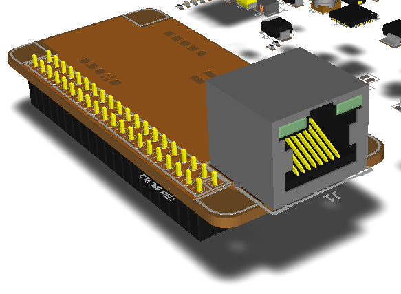
- off board Ethernet connector (could be used to bring the design to HAT specs)
- 100T-Base Ethernet (still possible)
- DC/DC 3.3V supply (opted for LDO instead)
Ethernet Selection
This was a heated discussion between me and a couple friends who have been giving me input. Two of them do kernel dev work so they where pretty upset about my choice of the ENC28J60 (its slow). My reason for this selection at the moment is that there is a lot of magnetics in a small area. Once I can scope it and see whats going on I will be able to upgrade the Ethernet. I dont see any reason why I wouldn't be able to use the ENC624J600.
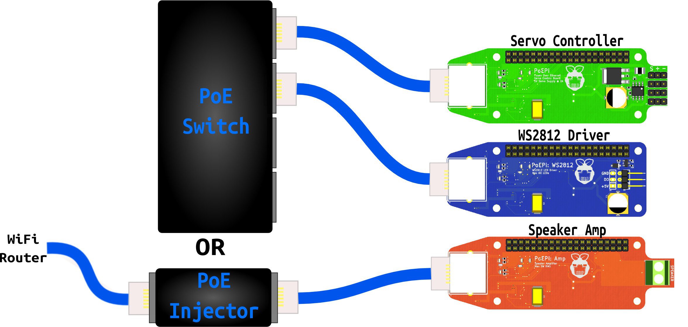
PoEPi Derivatives
These are boards that are designed around the PoEPi template. They are based on applications that I could see myself needing at home and work over the next year or so. When thinking of these applications I also try and thing of the alternative solutions
- PoEPi WS2812 controller and power supply (Done, boards ordered)
- Supply a chain of about 70 WS2812s while still powering the Pi
- Level shifting and protection on the GPIO that controls the Din pin.
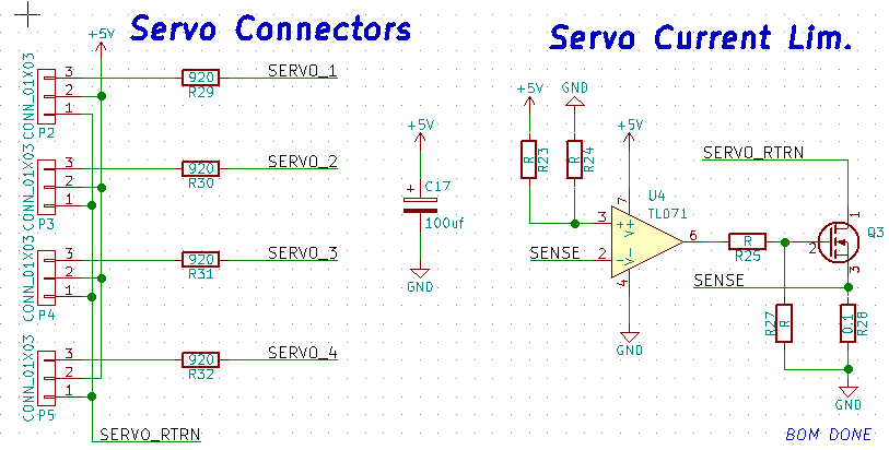
- PoEPi servo controller (probably working on it right now)
- control and power up to 8 servos
- current limiting to prevent Pi from restarting
- PoEPi speaker amplifier (Done)
- uses the Pi audio output (mono)
- integrated amplifier based on LM4871
- amplifier selected to eliminate the need for additional power supplies.
- amplifier shutdown pin controlled by the Pi
- RC circuit to act as DAC for PWM signal to amplifier

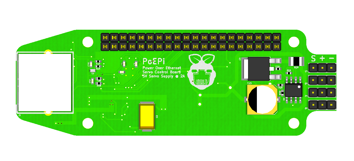


 The component selection and BOM are finished! Its always the hardest part and can require a lot of attention to detail. While creating the BOM i realized that I had sized one of the Caps wrong on the PoE circuit. With this cap to small the power would have been spotty at high loads.
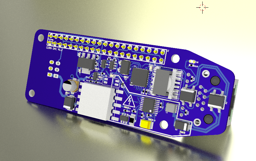


 Teemu Hakala
 Benchoff
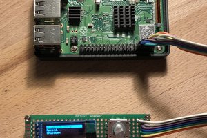
 Poyu Chen
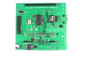
 Ryan Walmsley
I am real interested in this board specially since RPi ZERO 2 W now out this could give it more attention.