 julien
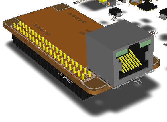
Sometimes you get deep into a schematic design and forget to ask the question where is it all going to fit? I assumed that an RJ45 would fit nicely at the end of the PiZero. Well it doesn't, it violates the footprint of the Pi connector and the mounting holes. It could be placed in the center of the board but that will seriously disrupt the flow of the routing (which will be tight).

An alternative is to overhang the connector. This violates the Hat specs but I dont yet see the benefit to constraining the board to those specs. Any ideas on where the RJ45 conn can go?
Discussions
Become a Hackaday.io Member
Create an account to leave a comment. Already have an account? Log In.
I personally would make an external connector board, connect them with a socketable cable. This way, it's awesome for making enclosures as you can actually place the jack anywhere, or even secure that in place relative to the pHat with a metal bracket and some screws, and a shorter cable. I think you can violate the Hat specs this way without punishment =)
Are you sure? yes | no
yeah the current design violates the mechanical standards for sure. Ill give this some serious thought because it would allow easy expansion to other projects as well.
Are you sure? yes | no
There are low profile RJ45 connectors (needs external magnetics).
http://www.te.com/usa-en/product-1888250-1.html
Are you sure? yes | no
cool part! But the width is the same so I cant put it between the mounting holes. I wish it wasnt 10$, its very cool.
Are you sure? yes | no
They use a similar style of connector in my $3.5 USB hub + 100BaseT dongle, so there got to be a much cheaper source from China.
I don't own any Pi related product, but those clearances for standoff looks huge in the picture. There are Chinese (metirc) brass standoff that takes the same amount of clearance as a nut.
Are you sure? yes | no
There are some cheap ones from Digikey as well, $3.50 when you buy one. We will save about 2mm in height with this part which would put the top of the Ethernet connector on the same plane as the top of the Pi. That would look sweet, If you clip of the LED pins it is pin compatible with the current connector. Ill see if I can incorperate both LED pins.
Are you sure? yes | no
If TE's site ever lets me download the part Ill render is into the existing model to see how it looks.
Are you sure? yes | no
There is a 3D model for the TE connector 1888250-2 on http://www.3dcontentcentral.com
It requires you to register etc. to see the page because it is a vendor model. Their registering is relatively painless. I use a lot of 3D models from the site for my Eagle CAD modelling. They offer a lot of formats for downloads.
http://www.3dcontentcentral.com/Search.aspx?arg=rj45&keywordsnavigator=Electronic%20connectors&page=6
entry: "Cat 5 modular RJ45 jack, 8/8, R/A, 2xLED"
Are you sure? yes | no
Maybe of interest, someone on Hacker News mentioned they were routing Ethernet signals through the extra pins of a USB-C connector https://news.ycombinator.com/item?id=10944252. Perhaps that plus a USB-C <-> RJ45 pig tale would help.
Are you sure? yes | no