 Patrick Van Oosterwijck
The Tinkermill hackerspace where I have my office just acquired a FLIR ONE thermal camera, so I decided to put it to good use in evaluating my thermally improved layout of the #LiFePO4wered/USB base board, compared to the original one.
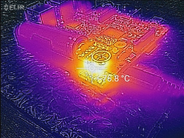
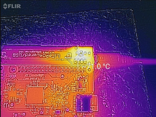
Here are thermal images of the prototype using the original layout, running an idle Pi 3, about half an hour into a charge cycle from empty, with a heat sink on the charging chip:
Here are the same shots with the new layout, with NO heat sink on the chip:
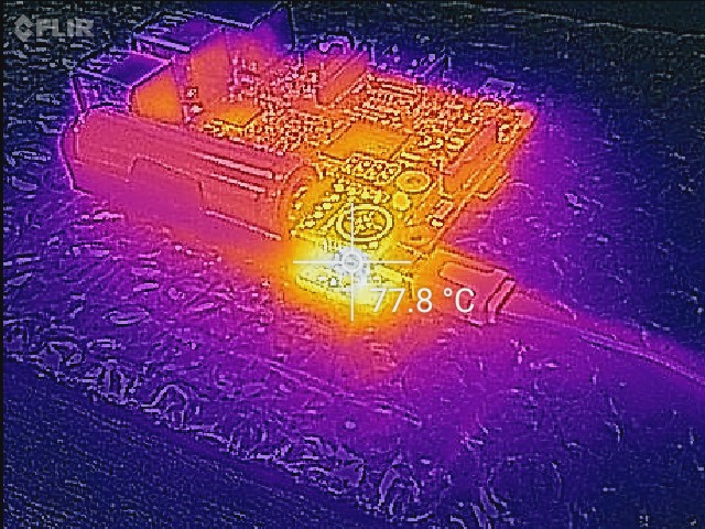
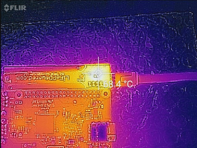
As you can clearly see in the thermal images of the bottom, the new layout does a much better job of pulling the heat into the PCB tail that goes to the battery's negative terminal. In the original layout, the heat stays much more localized on the business end of the PCB.
I need to do a little more testing before I can document the results with the improved layout, but I can already tell you that it seems to perform just as good or better without a heat sink as the original layout did with a heat sink!
Stay tuned for more!
Discussions
Become a Hackaday.io Member
Create an account to leave a comment. Already have an account? Log In.
We got one of those in the lab at work a few months ago, and it never occurred to me to check the ground plane dissipation on my board's switcher. I'll have to try this in the next couple of weeks :)
Are you sure? yes | no
Very interesting!
Are you sure? yes | no
yay - free (to use) toys are awesome!
Are you sure? yes | no